EP1907632B1 - Structure marine cubique absorbant les chocs - Google Patents
Structure marine cubique absorbant les chocs Download PDFInfo
- Publication number
- EP1907632B1 EP1907632B1 EP06773465A EP06773465A EP1907632B1 EP 1907632 B1 EP1907632 B1 EP 1907632B1 EP 06773465 A EP06773465 A EP 06773465A EP 06773465 A EP06773465 A EP 06773465A EP 1907632 B1 EP1907632 B1 EP 1907632B1
- Authority
- EP
- European Patent Office
- Prior art keywords
- tubular members
- impact
- tubes
- marine
- absorbing
- Prior art date
- Legal status (The legal status is an assumption and is not a legal conclusion. Google has not performed a legal analysis and makes no representation as to the accuracy of the status listed.)
- Not-in-force
Links
- XLYOFNOQVPJJNP-UHFFFAOYSA-N water Substances O XLYOFNOQVPJJNP-UHFFFAOYSA-N 0.000 claims abstract description 13
- 239000000463 material Substances 0.000 claims abstract description 11
- 229910000831 Steel Inorganic materials 0.000 claims abstract description 6
- 239000010959 steel Substances 0.000 claims abstract description 6
- 238000003466 welding Methods 0.000 claims abstract description 6
- 230000001066 destructive effect Effects 0.000 claims abstract description 4
- 239000012530 fluid Substances 0.000 claims description 9
- 239000006260 foam Substances 0.000 claims description 6
- 238000004891 communication Methods 0.000 claims description 5
- 239000002023 wood Substances 0.000 claims description 4
- 239000000203 mixture Substances 0.000 claims description 3
- 238000003491 array Methods 0.000 claims 1
- 239000011248 coating agent Substances 0.000 claims 1
- 238000000576 coating method Methods 0.000 claims 1
- JEIPFZHSYJVQDO-UHFFFAOYSA-N iron(III) oxide Inorganic materials O=[Fe]O[Fe]=O JEIPFZHSYJVQDO-UHFFFAOYSA-N 0.000 claims 1
- 239000000945 filler Substances 0.000 abstract description 4
- 230000021715 photosynthesis, light harvesting Effects 0.000 abstract description 3
- 239000006261 foam material Substances 0.000 abstract description 2
- 238000012360 testing method Methods 0.000 description 13
- 239000006096 absorbing agent Substances 0.000 description 12
- 238000010276 construction Methods 0.000 description 12
- 238000006073 displacement reaction Methods 0.000 description 12
- 239000004033 plastic Substances 0.000 description 12
- 229920003023 plastic Polymers 0.000 description 12
- WSFSSNUMVMOOMR-UHFFFAOYSA-N Formaldehyde Chemical compound O=C WSFSSNUMVMOOMR-UHFFFAOYSA-N 0.000 description 6
- 230000004888 barrier function Effects 0.000 description 6
- 230000000750 progressive effect Effects 0.000 description 6
- 238000010521 absorption reaction Methods 0.000 description 5
- 239000013598 vector Substances 0.000 description 5
- 230000007423 decrease Effects 0.000 description 3
- 230000001681 protective effect Effects 0.000 description 3
- 229910000975 Carbon steel Inorganic materials 0.000 description 2
- 230000000712 assembly Effects 0.000 description 2
- 238000000429 assembly Methods 0.000 description 2
- 238000005452 bending Methods 0.000 description 2
- 239000010962 carbon steel Substances 0.000 description 2
- 230000003247 decreasing effect Effects 0.000 description 2
- 238000013461 design Methods 0.000 description 2
- 238000005553 drilling Methods 0.000 description 2
- 238000009434 installation Methods 0.000 description 2
- 230000003993 interaction Effects 0.000 description 2
- 238000000034 method Methods 0.000 description 2
- 230000002411 adverse Effects 0.000 description 1
- 230000003466 anti-cipated effect Effects 0.000 description 1
- 230000015572 biosynthetic process Effects 0.000 description 1
- 239000000969 carrier Substances 0.000 description 1
- 238000007796 conventional method Methods 0.000 description 1
- 230000007797 corrosion Effects 0.000 description 1
- 238000005260 corrosion Methods 0.000 description 1
- 239000010779 crude oil Substances 0.000 description 1
- 238000005520 cutting process Methods 0.000 description 1
- 229910003460 diamond Inorganic materials 0.000 description 1
- 239000010432 diamond Substances 0.000 description 1
- 230000003467 diminishing effect Effects 0.000 description 1
- 238000007599 discharging Methods 0.000 description 1
- 238000009826 distribution Methods 0.000 description 1
- 230000000694 effects Effects 0.000 description 1
- 230000009969 flowable effect Effects 0.000 description 1
- 230000007246 mechanism Effects 0.000 description 1
- 239000012528 membrane Substances 0.000 description 1
- 239000002184 metal Substances 0.000 description 1
- 238000012986 modification Methods 0.000 description 1
- 230000004048 modification Effects 0.000 description 1
- 238000003032 molecular docking Methods 0.000 description 1
- 239000003129 oil well Substances 0.000 description 1
- 229920002635 polyurethane Polymers 0.000 description 1
- 239000004814 polyurethane Substances 0.000 description 1
- 238000002360 preparation method Methods 0.000 description 1
- 239000012779 reinforcing material Substances 0.000 description 1
- 230000004044 response Effects 0.000 description 1
- 230000035939 shock Effects 0.000 description 1
- 239000007787 solid Substances 0.000 description 1
- 239000011343 solid material Substances 0.000 description 1
- 230000000153 supplemental effect Effects 0.000 description 1
Images




Classifications
-
- E—FIXED CONSTRUCTIONS
- E02—HYDRAULIC ENGINEERING; FOUNDATIONS; SOIL SHIFTING
- E02B—HYDRAULIC ENGINEERING
- E02B3/00—Engineering works in connection with control or use of streams, rivers, coasts, or other marine sites; Sealings or joints for engineering works in general
- E02B3/20—Equipment for shipping on coasts, in harbours or on other fixed marine structures, e.g. bollards
- E02B3/26—Fenders
-
- Y—GENERAL TAGGING OF NEW TECHNOLOGICAL DEVELOPMENTS; GENERAL TAGGING OF CROSS-SECTIONAL TECHNOLOGIES SPANNING OVER SEVERAL SECTIONS OF THE IPC; TECHNICAL SUBJECTS COVERED BY FORMER USPC CROSS-REFERENCE ART COLLECTIONS [XRACs] AND DIGESTS
- Y02—TECHNOLOGIES OR APPLICATIONS FOR MITIGATION OR ADAPTATION AGAINST CLIMATE CHANGE
- Y02A—TECHNOLOGIES FOR ADAPTATION TO CLIMATE CHANGE
- Y02A30/00—Adapting or protecting infrastructure or their operation
- Y02A30/30—Adapting or protecting infrastructure or their operation in transportation, e.g. on roads, waterways or railways
Definitions
- This invention relates to protective structures attached to marine facilities, such as docks, quays, off-shore gas and oil well drilling platforms and loading terminals, for absorbing potentially damaging impact forces from large vessels.
- While such structures may function to absorb a limited amount of energy, and perhaps deflect a glancing impact, such a unit can collapse under a larger impact force, absorbing little of the kinetic energy of the vessel, with the remaining excess energy being transferred to the underlying marine structure causing permanent damage.
- a further object of the invention is to provide an impact-absorbing structure that is reliable, relatively simple in design, economical to construct and easy to install.
- a novel impact-absorbing barrier structure is constructed from a plurality of tubular members of uniform cross-sectional configuration to provide a three-dimensional cubic structure.
- an individual unit of construction comprises tubular members that form the framework of an open cube. The general mode of construction and use of the structure is described in detail in co-pending application serial number 10/361,335 filed February 10, 2003 .
- the present invention is directed to an improved three-dimensional sacrificial marine impact energy-absorbing structure that consists of twelve tubes welded together in a particular configuration to form an open cubic cell that is positioned in a specified orientation on a marine facility.
- the horizontal tubes extending from the contact surface deform axially, while the tubes forming the array in the vertical impact plane deform laterally. Energy is absorbed both in the plastic buckling of tubes that are normal to the impact plane and in the plastic flattening of the tubes forming the vertical plane of the impact plane and the parallel rear plane.
- Eight of the tubular elements that are relatively shorter are joined to the remaining four longer elements that are oriented with their axes parallel to the open face units of the cubic structure.
- the four longer elements are oriented with their longitudinal axes normal to the exterior vertical surface of the protected marine facility.
- the four longer tubes are referred to as the normal tubes.
- the four normal tubes extend horizontally away from the marine facility supporting structure.
- the face of the unit mounted away from the marine facility is referred to as the plane of contact or impact surface.
- the normal tubes being relatively longer are preferably welded at their ends to the shorter tubes to form the corners of the unit. With this construction, a force applied to the outer impact or contact plane must pass through or be communicated by these four normal tubes. Although this is the preferred orientation, the cubic structure will also function as a sacrificial energy-absorbing structure when attached with the longer members parallel to the facility wall
- the tubular members are fabricated from mild, steel and welded together.
- the tubes can be galvanized or coated with other protective materials, such as polymeric materials of the types used for well casings and other underground installations.
- the tubular members are of circular cross-section.
- Carbon steel pipes are readily available and inexpensive.
- Other commercially available shapes, such as square and rectilinear tubing, can also be used.
- a round pipe offers advantages in maximizing energy-absorbing capacity when plastically deformed under destructive impact.
- a round cross-section also provides a more stable structure during impact and is less sensitive to the direction of the loading force.
- the tubing can have an outside diameter of from about 14cm to 30cm (6 inches to 15 inches) and have a wall thickness of from about 3mm to 13mm (0.125 inches to 0.5 inches).
- the tubing can be fabricated from carbon steel or similar material.
- the tubing should be of a material that can be cut and easily welded to facilitate assembly of the deformable barrier.
- the internal space defined by the interior of the tubes comprising the assembled structure is interconnected, that is, the interior space of one tube is in fluid communication with that of some or all of the tubes to which it is joined
- the internal fluid communication of this configuration is provided by cutting openings in the tubes prior to, or during the assembly of the tubes.
- One or more of the tubes are optionally filled with an impact-absorbing medium.
- the filler medium can be a rigid polymeric foam material, such as a polyurethane formaldehyde foam or other such material.
- One or more of the tubes can also be filled with water and the tubes provided with pressure relief orifices that are closed by plugs that rupture or are released from their fitting when the increased pressure of an impact is transmitted through the essentially incompressible water. The number and size of the pressure relief orifices is predetermined in order to optimize the energy dissipation offered by the structure.
- Different members of the structure can have none, one or a plurality of orifices of varying size and pressure relief values so that they begin discharging water at different times following impact and the destructive, energy-dissipating crushing of the structure's framework.
- the wall of an empty tube can also be provided with one or more orifices to permit water to pass from an adjacent tube that is filled with water.
- Submerged elements of the sacrificial impact-absorbing structure can be provided with small open ports to allow one or more of the tubes to fill with water that are submerged after installation on the facility to be protected.
- Rupture plugs and/or large pressure relief ports are optionally provided as described above.
- one or more filler ports are provided in the tubes at appropriate locations.
- selected tubes can be filled based on the predetermined direction(s) of probable maximum impact. For example, where a docking or tie-up platform is typically approached by barges or service ships from one direction, the impact zone and likely force vectors can be calculated, and from this information the corresponding force vectors transmitted to and through the impact-absorbing structure are determined.
- the maximum impact force vector is normal to the protected facility, tubes parallel to that vector are filled with a supplemental energy-absorbing medium that will serve to further dissipate the energy of impact as the containing tube is crushed or otherwise plastically deformed.
- the tubes can also be filled with a solid material such as wood.
- the wood can be in the form of new or used pilings, railroad ties or timber, or even smaller scraps or chips that are firmly packed into one or more of the tubes prior to assembly, but which will compress with resistance if the containing tube is deformed.
- a combination of rigid foam and unconsolidated wood filler material can be employed to minimize costs.
- the improved structure of the invention can be attached to an offshore or other marine facility using conventional methods and hardware known to the art.
- Means of attachment include welding to steel supporting legs of off-shore drilling platforms, bolted bracket assemblies, steel cables, and the like.
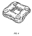
- Fig. 1 schematically illustrates one embodiment of the invention in the form of a cubic impact-absorbing framework 10 formed of tubes referred to generally as 12, having a circular cross section.
- Tubes 12a are optionally provided with sealed exposed end caps 14.
- Tubes 12b are cut at their respective ends 15 to conform to the outer contour of tubes 12a.
- the tubes 12a and 12b are of the same cross-section and diameter adding to the overall impact-absorbing capability of the framework structure.
- the orientation of the four normal tubes relative to the tubes forming the vertical plane is shown.
- several of the tubes 12a and 12b can be provided with optional filling ports 20 at predetermined locations to receive a flowable fluid, such as water, and/or an expandable rigid foam composition.
- the inlet port 20 can be a threaded plug 22, a valve 26 with threads to receive a hose fitting 24, or the like.
- one or more of the tubes 12 can be provided with one or a plurality of pressure relief or blow-off fittings 30.
- these fittings are optionally employed where one or more of the tubes is filled with an incompressible fluid, such as water, that will function to slow the rate of crushing or other deformation of the tubes 12.
- an incompressible fluid such as water
- Larger fittings can optionally be provided to permit the rapid discharge of water to minimize the likelihood that the tube 12 will rupture along a longitudinal seam, thereby diminishing its energy-absorbing capacity, and perhaps the integrity of the associated framework structure.
- the ends of the shorter connecting elements are cut to the contour of the longer longitudinal elements in preparation for welding.
- the elements 12a that extend in the same general direction as the anticipated maximum force vector F of an accidental impact can optionally be filled with scrap lumber and timbers of random length. They can subsequently be filled with a rigid formaldehyde foam via previously installed fittings to provide additional resistance to the plastic deformation of the tubular steel elements in the event of an impact.
- the placement of these reinforcing materials in the elements that will absorb the maximum energy of an impact will serve to minimize damage to the hull of a barge or ship in the event of an accidental impact.
- the test structures were constructed in accordance with FIG. 1 where the absorber consists of four vertical tubes joined together by eight horizontal tubes. Due to the orientation of the testing machine, the cube is rotated 90° from what would be its position when mounted on a marine facility. The impact surface is therefore horizontal during the testing and is referred to as the upper unit and will be crushed to move in the direction of the lower unit.
- the normal tubes are vertically oriented in the testing machine.
- the length of the normal tubes which is the maximum dimension of the cube is L.
- the remaining tubes ones are shorter by approximately two times the outside diameter (D), as shown in FIGS. 1 and 2 .
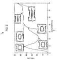
- FIG. 3 An absorption curve for crushing the marine cubic tubular absorber is shown in FIG. 3 in which the load (kN) is plotted against the displacement in millimeters (mm).
- the progressive collapse starts at either the upper or the lower sides of the vertical tubes, but with no general pattern for this distribution.
- the photos at 30-mm and 40-mm displacement were taken while the load is increasing due to the resistance of the second convolution formation. Because of the short vertical tubes, the second convolution in the vertical tubes did not proceed independently and deformation extends into the eight joints as shown in the photo taken at 56-mm displacement.
- a large aspect ratio means a large cell with long vertical tubes that tend to collapse in the Euler buckling mode.
- the general trend is the same in these curves and the average crushing force increases with the increase in tube diameter.
- the square wave pattern of the loading curve is desirable in designing impact energy absorbers because it produces a constant deceleration of the vessel and any passengers that may be on board.
- the uniformity in the load after the initial peak is attributable to the interactions between the progressive plastic buckling of the four normal tubes.
- the progressive collapse of the four tubes was not simultaneous. Due to welding, the tubes do not react independently and do not follow each other precisely in the crumpling sequence.
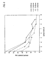
- FIGS. 8 and 9 Specific energy for each specimen is plotted in FIGS. 8 and 9 .
- the specific energy (J/g) is plotted vs. the aspect ratio for the four diameters tested.
- the data establishes that tubes with smaller diameters are more efficient than the larger ones.
- the shape selected for extended testing was circular and the data demonstrates good results with respect to uniform crumpling of the components normal to the impact plane and flattening of the tubes in the vertically oriented planes.
- the invention broadly contemplates the use of tubes having other cross-sections, including square, rectangular and those having arcuate corners and flat or planar sides.
- Other shapes, such as oval and elliptical can also be utilised, with the longer axis of the ellipse being oriented normal to the plane of impact to maximize the resistance to flattening.
- the resistance of the normal tubular members to crumpling under the impact force can be increased by increasing the wall thickness of the tubes.
- the tubular members in order to serve as a sacrificial impact absorber the tubular members must begin to plastically deform under a load that can be withstood by the marine facility to which the structure is attached. In other words, a damaging force of impact should not be transmitted to the marine facility supports without deformation of the normal members.
- the size and wall thickness of the tubular members is determined with reference to the nature of the marine facility's construction. Determination of these engineering parameters is within the routine skill in the art
Landscapes
- Engineering & Computer Science (AREA)
- General Engineering & Computer Science (AREA)
- Ocean & Marine Engineering (AREA)
- Environmental & Geological Engineering (AREA)
- Mechanical Engineering (AREA)
- Civil Engineering (AREA)
- Structural Engineering (AREA)
- Vibration Dampers (AREA)
- Revetment (AREA)
Abstract
Claims (12)
- Structure sacrificielle d'absorption des impacts et de dissipation d'énergie pour le montage sur un aménagement de marine pour protéger l'aménagement contre la force destructrice d'un impact accidentel par un navire de marine, la structure comprenant:a. une première rangée plane de quatre éléments tubulaires plastiquement déformables assemblés en permanence pour former un carré;b. une deuxième rangée plane de quatre éléments tubulaires plastiquement déformables assemblés en permanence pour former un carré; etc. quatre éléments tubulaires de jonction, plastiquement déformables, dont les extrémités opposées sont assemblées en permanence à des coins correspondants des première et deuxième rangées planes pour former ainsi un châssis ouvert rigide, sensiblement cubique,caractérisée en ce que le rapport d'aspect R des éléments tubulaires plastiquement déformables est égal à 5, où R est le rapport de la longueur d'un côté du châssis cubique au diamètre extérieur d'un élément tubulaire circulaire.
- Structure selon la revendication 1, dans laquelle les éléments tubulaires ont une zone en section transversale et épaisseur de paroi sensiblement égales.
- Structure selon la revendication 1, dans laquelle les éléments tubulaires ont une section transversale circulaire, et le diamètre extérieur et l'épaisseur de paroi de tous les éléments tubulaires sont les mêmes.
- Structure selon la revendication 1, dans laquelle les éléments tubulaires sont en acier et sont assemblés par soudage.
- Structure selon la revendication 4, où les éléments tubulaires sont pourvus d'un revêtement résistant à la rouille.
- Structure selon la revendication 1, dans laquelle les espaces intérieurs de deux ou plusieurs éléments tubulaires comprenant le châssis sont en communication fluidique.
- Structure selon la revendication 6, dans laquelle la communication fluidique est réalisée par une seule ouverture dans un premier élément tubulaire à sa jonction avec un deuxième élément.
- Structure selon la revendication 6, qui comprend en outre un ou plusieurs orifices d'entrée de fluide.
- Structure selon la revendication 8, qui comprend en outre un ou plusieurs dispositifs de détente de pression communiquant avec l'espace intérieur défini par un ou plusieurs éléments tubulaires, moyennant quoi la pression transmise par un fluide, par la déformation de la structure, peut être détendue.
- Structure selon la revendication 1, dans laquelle l'espace intérieur défini par un ou plusieurs des éléments tubulaires est occupé par un matériau sélectionné dans le groupe consistant en eau, une composition de mousse rigide expansée, bois, et une combinaison de ces matériaux.
- Structure selon la revendication 9, dans laquelle les dispositifs de détente de pression sont actionnés à une pression prédéterminée transmise à l'intérieur de l'élément tubulaire.
- Structure selon la revendication 11, dans laquelle une pluralité de dispositifs de détente de pression ayant des pressions d'actionnement prédéterminées différentes sont installés sur un ou plusieurs des éléments tubulaires.
Applications Claiming Priority (2)
| Application Number | Priority Date | Filing Date | Title |
|---|---|---|---|
| US11/173,077 US7396189B2 (en) | 2005-07-01 | 2005-07-01 | Cubic marine impact-absorbing structure |
| PCT/US2006/023693 WO2007005247A2 (fr) | 2005-07-01 | 2006-06-15 | Structure marine cubique absorbant les chocs |
Publications (3)
| Publication Number | Publication Date |
|---|---|
| EP1907632A2 EP1907632A2 (fr) | 2008-04-09 |
| EP1907632A4 EP1907632A4 (fr) | 2011-07-20 |
| EP1907632B1 true EP1907632B1 (fr) | 2012-06-06 |
Family
ID=37589730
Family Applications (1)
| Application Number | Title | Priority Date | Filing Date |
|---|---|---|---|
| EP06773465A Not-in-force EP1907632B1 (fr) | 2005-07-01 | 2006-06-15 | Structure marine cubique absorbant les chocs |
Country Status (5)
| Country | Link |
|---|---|
| US (1) | US7396189B2 (fr) |
| EP (1) | EP1907632B1 (fr) |
| CN (1) | CN101400859B (fr) |
| NO (1) | NO340033B1 (fr) |
| WO (1) | WO2007005247A2 (fr) |
Families Citing this family (3)
| Publication number | Priority date | Publication date | Assignee | Title |
|---|---|---|---|---|
| CN104636541B (zh) * | 2014-12-30 | 2017-11-24 | 浙江大学 | 一种变异卵圆形仿生减阻降噪柔性结构 |
| CN106906786B (zh) * | 2017-03-27 | 2022-05-17 | 大连海洋大学 | 一种半潜透空式消浪装置及消浪方法 |
| CN114575290B (zh) * | 2022-03-07 | 2022-12-06 | 湖南大学 | 一种船舶拦截系统及其应用 |
Family Cites Families (27)
| Publication number | Priority date | Publication date | Assignee | Title |
|---|---|---|---|---|
| US1302293A (en) * | 1916-11-04 | 1919-04-29 | Earl H Blazer | Aeroplane-frame construction. |
| US3404534A (en) * | 1967-04-17 | 1968-10-08 | Edward G. Cunney | Energy-absorbing camel |
| US3541800A (en) * | 1968-09-17 | 1970-11-24 | Grant W Walker | Pile protector |
| FR1585391A (fr) * | 1968-11-13 | 1970-01-16 | ||
| US3564858A (en) * | 1969-04-01 | 1971-02-23 | Texaco Inc | Boat landing for offshore structure |
| US3721433A (en) * | 1969-11-21 | 1973-03-20 | Collision Devices Inc | Deformable shock-absorbing guard |
| JPS4915877A (fr) * | 1972-06-09 | 1974-02-12 | ||
| US3856268A (en) * | 1973-09-17 | 1974-12-24 | Fibco Inc | Highway safety device |
| US3898958A (en) * | 1974-06-13 | 1975-08-12 | Jr Peter P Pranis | Open water fish farming apparatus |
| US4135467A (en) * | 1976-04-30 | 1979-01-23 | Entreprise D'equipements Mecaniques Et Hydrauliques E.M.H. | Means of protection against the shocks of ships coming alongside, particularly for platforms of the off-shore type |
| US4058984A (en) * | 1976-06-18 | 1977-11-22 | Brown & Root, Inc. | Marine cushioning unit |
| US4118014A (en) * | 1977-08-19 | 1978-10-03 | Nasa | Vehicular impact absorption system |
| US4337009A (en) * | 1979-07-27 | 1982-06-29 | Regal International, Inc. | Marine landing structure with omni directional energy absorbing characteristics |
| US4337010A (en) * | 1979-12-13 | 1982-06-29 | Halliburton Company | Inflatable grout seal |
| US4352484A (en) * | 1980-09-05 | 1982-10-05 | Energy Absorption Systems, Inc. | Shear action and compression energy absorber |
| FR2500098B1 (fr) * | 1981-02-13 | 1985-12-06 | Commissariat Energie Atomique | Dispositif d'amortissement contre les chocs provoques par des objets lourds |
| US4398848A (en) * | 1981-05-04 | 1983-08-16 | Guilbeau Edgar A | Marine energy cell |
| US4645375A (en) * | 1985-05-23 | 1987-02-24 | State Of Connecticut | Stationary impact attenuation system |
| US4880088A (en) * | 1988-11-07 | 1989-11-14 | Conoco Inc. | Collision protecting system for TLP structures |
| CN1013602B (zh) * | 1988-12-13 | 1991-08-21 | 陆建衡 | 建筑物消震装置 |
| US4958960A (en) * | 1989-05-22 | 1990-09-25 | Exxon Production Research Company | Well conductor support structure and method for using |
| US4968184A (en) * | 1989-06-23 | 1990-11-06 | Halliburton Company | Grout packer |
| US5480265A (en) * | 1993-12-30 | 1996-01-02 | Shell Oil Company | Method for improving the harmonic response of a compliant tower |
| NO306289B1 (no) * | 1996-12-18 | 1999-10-18 | Offshore Shuttle As | FremgangsmÕte og transportör til bruk ved installasjon eller fjerning av et understell for en offshoreplattform |
| US6178909B1 (en) * | 1999-06-25 | 2001-01-30 | Randy C. Palmer | Water craft and dock protector assembly |
| US6644893B2 (en) * | 2001-07-09 | 2003-11-11 | Marathon Oil Company | Rigid jacket of an offshore platform having a quadrapod structure |
| US6851892B2 (en) * | 2003-02-10 | 2005-02-08 | Saudi Arabian Oil Company | Marine impact-absorbing structure |
-
2005
- 2005-07-01 US US11/173,077 patent/US7396189B2/en active Active
-
2006
- 2006-06-15 WO PCT/US2006/023693 patent/WO2007005247A2/fr not_active Ceased
- 2006-06-15 EP EP06773465A patent/EP1907632B1/fr not_active Not-in-force
- 2006-06-15 CN CN2006800321487A patent/CN101400859B/zh not_active Expired - Fee Related
-
2008
- 2008-01-22 NO NO20080422A patent/NO340033B1/no not_active IP Right Cessation
Also Published As
| Publication number | Publication date |
|---|---|
| EP1907632A2 (fr) | 2008-04-09 |
| US7396189B2 (en) | 2008-07-08 |
| US20070003373A1 (en) | 2007-01-04 |
| WO2007005247A3 (fr) | 2008-10-30 |
| CN101400859B (zh) | 2013-01-16 |
| NO20080422L (no) | 2008-03-31 |
| CN101400859A (zh) | 2009-04-01 |
| NO340033B1 (no) | 2017-02-27 |
| EP1907632A4 (fr) | 2011-07-20 |
| WO2007005247A2 (fr) | 2007-01-11 |
Similar Documents
| Publication | Publication Date | Title |
|---|---|---|
| Hales | Floating Breakwaters: State-of-the-Art Literature Review. | |
| AU2004225701B2 (en) | Wave power apparatus | |
| US7097387B2 (en) | Engineered material buoyancy system and device | |
| US20060159523A1 (en) | Underwater enclosure apparatus and method for constructing the same | |
| US3933111A (en) | Dock bumper unit | |
| US6543485B2 (en) | Waterhammer suppression apparatus | |
| US10215540B2 (en) | Open water marine barrier systems | |
| US5553977A (en) | Off-shore platform construction, and method for transferring loads | |
| US4642000A (en) | Anchoring system for concrete floating pier | |
| EP1907632B1 (fr) | Structure marine cubique absorbant les chocs | |
| US3804395A (en) | Pressurized rubber for absorbing impact energy | |
| US4607586A (en) | Preloaded compression absorber cell for boat bumpers | |
| US6851892B2 (en) | Marine impact-absorbing structure | |
| Voyiadjis et al. | Feasibility of tubular fender units for pier protection against vessel collision | |
| Amdahl et al. | Broad side ship collision with jacket legs: examination of NORSOK N-004 analysis procedure | |
| Tavakoli et al. | Investigation of interaction between oil spills and hydrostatic changes | |
| Ozguc | Collision damage analysis of FPSO hull caisson protection structure | |
| Noble | Use of wave-maze flexible floating breakwater to protect offshore structures and landings | |
| RU2536473C2 (ru) | Балочный узел и промежуточный элемент | |
| EP4649215A1 (fr) | Stockage flexible | |
| Aberle et al. | Mid depth buoys design for long life using syntactic foam buoyancy, redundant and replaceable tether systems | |
| Malfanti | Analysis of existing marine fendering systems and analysis of a marine fender system utilizing torsional resistance. | |
| JPH0333323A (ja) | 水中構造物配置用緩衝材 | |
| JPH04140321A (ja) | 変位抑制装置を有する重力着底式海洋構造物 |
Legal Events
| Date | Code | Title | Description |
|---|---|---|---|
| PUAI | Public reference made under article 153(3) epc to a published international application that has entered the european phase |
Free format text: ORIGINAL CODE: 0009012 |
|
| 17P | Request for examination filed |
Effective date: 20080201 |
|
| AK | Designated contracting states |
Kind code of ref document: A2 Designated state(s): AT BE BG CH CY CZ DE DK EE ES FI FR GB GR HU IE IS IT LI LT LU LV MC NL PL PT RO SE SI SK TR |
|
| AX | Request for extension of the european patent |
Extension state: AL BA HR MK RS |
|
| DAX | Request for extension of the european patent (deleted) | ||
| R17D | Deferred search report published (corrected) |
Effective date: 20081030 |
|
| RIN1 | Information on inventor provided before grant (corrected) |
Inventor name: AL-GHAMDI, ABDULMALIK A. Inventor name: RADWAN, ABOBAKR M.SAUDI ARAMCO |
|
| RAP1 | Party data changed (applicant data changed or rights of an application transferred) |
Owner name: SAUDI ARABIAN OIL COMPANY |
|
| A4 | Supplementary search report drawn up and despatched |
Effective date: 20110621 |
|
| GRAP | Despatch of communication of intention to grant a patent |
Free format text: ORIGINAL CODE: EPIDOSNIGR1 |
|
| GRAS | Grant fee paid |
Free format text: ORIGINAL CODE: EPIDOSNIGR3 |
|
| GRAA | (expected) grant |
Free format text: ORIGINAL CODE: 0009210 |
|
| AK | Designated contracting states |
Kind code of ref document: B1 Designated state(s): AT BE BG CH CY CZ DE DK EE ES FI FR GB GR HU IE IS IT LI LT LU LV MC NL PL PT RO SE SI SK TR |
|
| REG | Reference to a national code |
Ref country code: GB Ref legal event code: FG4D |
|
| REG | Reference to a national code |
Ref country code: CH Ref legal event code: EP Ref country code: AT Ref legal event code: REF Ref document number: 561116 Country of ref document: AT Kind code of ref document: T Effective date: 20120615 |
|
| REG | Reference to a national code |
Ref country code: IE Ref legal event code: FG4D |
|
| REG | Reference to a national code |
Ref country code: DE Ref legal event code: R096 Ref document number: 602006029970 Country of ref document: DE Effective date: 20120802 |
|
| REG | Reference to a national code |
Ref country code: NL Ref legal event code: T3 |
|
| PG25 | Lapsed in a contracting state [announced via postgrant information from national office to epo] |
Ref country code: SE Free format text: LAPSE BECAUSE OF FAILURE TO SUBMIT A TRANSLATION OF THE DESCRIPTION OR TO PAY THE FEE WITHIN THE PRESCRIBED TIME-LIMIT Effective date: 20120606 Ref country code: FI Free format text: LAPSE BECAUSE OF FAILURE TO SUBMIT A TRANSLATION OF THE DESCRIPTION OR TO PAY THE FEE WITHIN THE PRESCRIBED TIME-LIMIT Effective date: 20120606 Ref country code: LT Free format text: LAPSE BECAUSE OF FAILURE TO SUBMIT A TRANSLATION OF THE DESCRIPTION OR TO PAY THE FEE WITHIN THE PRESCRIBED TIME-LIMIT Effective date: 20120606 Ref country code: CY Free format text: LAPSE BECAUSE OF FAILURE TO SUBMIT A TRANSLATION OF THE DESCRIPTION OR TO PAY THE FEE WITHIN THE PRESCRIBED TIME-LIMIT Effective date: 20120606 |
|
| REG | Reference to a national code |
Ref country code: AT Ref legal event code: MK05 Ref document number: 561116 Country of ref document: AT Kind code of ref document: T Effective date: 20120606 |
|
| REG | Reference to a national code |
Ref country code: LT Ref legal event code: MG4D Effective date: 20120606 |
|
| PG25 | Lapsed in a contracting state [announced via postgrant information from national office to epo] |
Ref country code: SI Free format text: LAPSE BECAUSE OF FAILURE TO SUBMIT A TRANSLATION OF THE DESCRIPTION OR TO PAY THE FEE WITHIN THE PRESCRIBED TIME-LIMIT Effective date: 20120606 Ref country code: LV Free format text: LAPSE BECAUSE OF FAILURE TO SUBMIT A TRANSLATION OF THE DESCRIPTION OR TO PAY THE FEE WITHIN THE PRESCRIBED TIME-LIMIT Effective date: 20120606 Ref country code: GR Free format text: LAPSE BECAUSE OF FAILURE TO SUBMIT A TRANSLATION OF THE DESCRIPTION OR TO PAY THE FEE WITHIN THE PRESCRIBED TIME-LIMIT Effective date: 20120907 |
|
| PG25 | Lapsed in a contracting state [announced via postgrant information from national office to epo] |
Ref country code: EE Free format text: LAPSE BECAUSE OF FAILURE TO SUBMIT A TRANSLATION OF THE DESCRIPTION OR TO PAY THE FEE WITHIN THE PRESCRIBED TIME-LIMIT Effective date: 20120606 Ref country code: RO Free format text: LAPSE BECAUSE OF FAILURE TO SUBMIT A TRANSLATION OF THE DESCRIPTION OR TO PAY THE FEE WITHIN THE PRESCRIBED TIME-LIMIT Effective date: 20120606 Ref country code: AT Free format text: LAPSE BECAUSE OF FAILURE TO SUBMIT A TRANSLATION OF THE DESCRIPTION OR TO PAY THE FEE WITHIN THE PRESCRIBED TIME-LIMIT Effective date: 20120606 Ref country code: CZ Free format text: LAPSE BECAUSE OF FAILURE TO SUBMIT A TRANSLATION OF THE DESCRIPTION OR TO PAY THE FEE WITHIN THE PRESCRIBED TIME-LIMIT Effective date: 20120606 Ref country code: SK Free format text: LAPSE BECAUSE OF FAILURE TO SUBMIT A TRANSLATION OF THE DESCRIPTION OR TO PAY THE FEE WITHIN THE PRESCRIBED TIME-LIMIT Effective date: 20120606 Ref country code: MC Free format text: LAPSE BECAUSE OF NON-PAYMENT OF DUE FEES Effective date: 20120630 Ref country code: IS Free format text: LAPSE BECAUSE OF FAILURE TO SUBMIT A TRANSLATION OF THE DESCRIPTION OR TO PAY THE FEE WITHIN THE PRESCRIBED TIME-LIMIT Effective date: 20121006 Ref country code: BE Free format text: LAPSE BECAUSE OF FAILURE TO SUBMIT A TRANSLATION OF THE DESCRIPTION OR TO PAY THE FEE WITHIN THE PRESCRIBED TIME-LIMIT Effective date: 20120606 |
|
| REG | Reference to a national code |
Ref country code: CH Ref legal event code: PL |
|
| REG | Reference to a national code |
Ref country code: CH Ref legal event code: PL |
|
| PG25 | Lapsed in a contracting state [announced via postgrant information from national office to epo] |
Ref country code: PL Free format text: LAPSE BECAUSE OF FAILURE TO SUBMIT A TRANSLATION OF THE DESCRIPTION OR TO PAY THE FEE WITHIN THE PRESCRIBED TIME-LIMIT Effective date: 20120606 Ref country code: PT Free format text: LAPSE BECAUSE OF FAILURE TO SUBMIT A TRANSLATION OF THE DESCRIPTION OR TO PAY THE FEE WITHIN THE PRESCRIBED TIME-LIMIT Effective date: 20121008 Ref country code: IT Free format text: LAPSE BECAUSE OF FAILURE TO SUBMIT A TRANSLATION OF THE DESCRIPTION OR TO PAY THE FEE WITHIN THE PRESCRIBED TIME-LIMIT Effective date: 20120606 |
|
| REG | Reference to a national code |
Ref country code: IE Ref legal event code: MM4A |
|
| PLBE | No opposition filed within time limit |
Free format text: ORIGINAL CODE: 0009261 |
|
| STAA | Information on the status of an ep patent application or granted ep patent |
Free format text: STATUS: NO OPPOSITION FILED WITHIN TIME LIMIT |
|
| REG | Reference to a national code |
Ref country code: DE Ref legal event code: R119 Ref document number: 602006029970 Country of ref document: DE Effective date: 20130101 |
|
| PG25 | Lapsed in a contracting state [announced via postgrant information from national office to epo] |
Ref country code: ES Free format text: LAPSE BECAUSE OF FAILURE TO SUBMIT A TRANSLATION OF THE DESCRIPTION OR TO PAY THE FEE WITHIN THE PRESCRIBED TIME-LIMIT Effective date: 20120917 Ref country code: CH Free format text: LAPSE BECAUSE OF NON-PAYMENT OF DUE FEES Effective date: 20120630 Ref country code: DK Free format text: LAPSE BECAUSE OF FAILURE TO SUBMIT A TRANSLATION OF THE DESCRIPTION OR TO PAY THE FEE WITHIN THE PRESCRIBED TIME-LIMIT Effective date: 20120606 Ref country code: DE Free format text: LAPSE BECAUSE OF NON-PAYMENT OF DUE FEES Effective date: 20130101 Ref country code: IE Free format text: LAPSE BECAUSE OF NON-PAYMENT OF DUE FEES Effective date: 20120615 Ref country code: LI Free format text: LAPSE BECAUSE OF NON-PAYMENT OF DUE FEES Effective date: 20120630 |
|
| 26N | No opposition filed |
Effective date: 20130307 |
|
| REG | Reference to a national code |
Ref country code: FR Ref legal event code: ST Effective date: 20130426 |
|
| PG25 | Lapsed in a contracting state [announced via postgrant information from national office to epo] |
Ref country code: BG Free format text: LAPSE BECAUSE OF FAILURE TO SUBMIT A TRANSLATION OF THE DESCRIPTION OR TO PAY THE FEE WITHIN THE PRESCRIBED TIME-LIMIT Effective date: 20120906 |
|
| PG25 | Lapsed in a contracting state [announced via postgrant information from national office to epo] |
Ref country code: FR Free format text: LAPSE BECAUSE OF NON-PAYMENT OF DUE FEES Effective date: 20120806 |
|
| PG25 | Lapsed in a contracting state [announced via postgrant information from national office to epo] |
Ref country code: TR Free format text: LAPSE BECAUSE OF FAILURE TO SUBMIT A TRANSLATION OF THE DESCRIPTION OR TO PAY THE FEE WITHIN THE PRESCRIBED TIME-LIMIT Effective date: 20120606 |
|
| PG25 | Lapsed in a contracting state [announced via postgrant information from national office to epo] |
Ref country code: LU Free format text: LAPSE BECAUSE OF NON-PAYMENT OF DUE FEES Effective date: 20120615 |
|
| PG25 | Lapsed in a contracting state [announced via postgrant information from national office to epo] |
Ref country code: HU Free format text: LAPSE BECAUSE OF FAILURE TO SUBMIT A TRANSLATION OF THE DESCRIPTION OR TO PAY THE FEE WITHIN THE PRESCRIBED TIME-LIMIT Effective date: 20060615 |
|
| PGFP | Annual fee paid to national office [announced via postgrant information from national office to epo] |
Ref country code: NL Payment date: 20180626 Year of fee payment: 13 |
|
| PGFP | Annual fee paid to national office [announced via postgrant information from national office to epo] |
Ref country code: GB Payment date: 20180627 Year of fee payment: 13 |
|
| REG | Reference to a national code |
Ref country code: NL Ref legal event code: MM Effective date: 20190701 |
|
| GBPC | Gb: european patent ceased through non-payment of renewal fee |
Effective date: 20190615 |
|
| PG25 | Lapsed in a contracting state [announced via postgrant information from national office to epo] |
Ref country code: GB Free format text: LAPSE BECAUSE OF NON-PAYMENT OF DUE FEES Effective date: 20190615 Ref country code: NL Free format text: LAPSE BECAUSE OF NON-PAYMENT OF DUE FEES Effective date: 20190701 |