EP1907649B1 - Ensemble baguette d'angle et son procédé de pose - Google Patents
Ensemble baguette d'angle et son procédé de pose Download PDFInfo
- Publication number
- EP1907649B1 EP1907649B1 EP06765367A EP06765367A EP1907649B1 EP 1907649 B1 EP1907649 B1 EP 1907649B1 EP 06765367 A EP06765367 A EP 06765367A EP 06765367 A EP06765367 A EP 06765367A EP 1907649 B1 EP1907649 B1 EP 1907649B1
- Authority
- EP
- European Patent Office
- Prior art keywords
- corner bead
- corner
- flanges
- clips
- arms
- Prior art date
- Legal status (The legal status is an assumption and is not a legal conclusion. Google has not performed a legal analysis and makes no representation as to the accuracy of the status listed.)
- Not-in-force
Links
- 239000011324 bead Substances 0.000 title claims abstract description 104
- 238000000034 method Methods 0.000 title claims description 9
- 239000000463 material Substances 0.000 claims description 9
- 239000002184 metal Substances 0.000 claims description 8
- 230000015572 biosynthetic process Effects 0.000 claims description 7
- 239000011449 brick Substances 0.000 description 8
- 239000011505 plaster Substances 0.000 description 6
- 238000005755 formation reaction Methods 0.000 description 5
- 239000004570 mortar (masonry) Substances 0.000 description 5
- 239000000853 adhesive Substances 0.000 description 4
- 230000001070 adhesive effect Effects 0.000 description 4
- 239000011248 coating agent Substances 0.000 description 2
- 238000000576 coating method Methods 0.000 description 2
- 229910000639 Spring steel Inorganic materials 0.000 description 1
- 229910000831 Steel Inorganic materials 0.000 description 1
- 230000001154 acute effect Effects 0.000 description 1
- 230000000295 complement effect Effects 0.000 description 1
- 238000004080 punching Methods 0.000 description 1
- 239000007787 solid Substances 0.000 description 1
- 239000010959 steel Substances 0.000 description 1
Images


Classifications
-
- E—FIXED CONSTRUCTIONS
- E04—BUILDING
- E04F—FINISHING WORK ON BUILDINGS, e.g. STAIRS, FLOORS
- E04F13/00—Coverings or linings, e.g. for walls or ceilings
- E04F13/02—Coverings or linings, e.g. for walls or ceilings of plastic materials hardening after applying, e.g. plaster
- E04F13/04—Bases for plaster
- E04F13/06—Edge-protecting borders
-
- E—FIXED CONSTRUCTIONS
- E04—BUILDING
- E04F—FINISHING WORK ON BUILDINGS, e.g. STAIRS, FLOORS
- E04F19/00—Other details of constructional parts for finishing work on buildings
- E04F19/02—Borders; Finishing strips, e.g. beadings; Light coves
-
- E—FIXED CONSTRUCTIONS
- E04—BUILDING
- E04F—FINISHING WORK ON BUILDINGS, e.g. STAIRS, FLOORS
- E04F13/00—Coverings or linings, e.g. for walls or ceilings
- E04F13/02—Coverings or linings, e.g. for walls or ceilings of plastic materials hardening after applying, e.g. plaster
- E04F13/04—Bases for plaster
- E04F13/06—Edge-protecting borders
- E04F2013/063—Edge-protecting borders for corners
Definitions
- the present invention relates to a corner bead assembly for applying to an external corner between two intersecting surfaces prior to the application of a surface coating thereto.
- US Patent No 4,876,837 discloses a typical corner bead which is formed from an elongate strip of sheet metal and comprises a rounded nose and two mounting flanges extending perpendicular to each other from the opposite sides of the nose.
- the mounting flanges are apertured to provide a key for the overlying plaster or render.
- the corner bead is applied to a corner by passing nails or screws through the apertured mounting flanges into the underlying wall material.
- a disadvantage of this arrangement is that the underlying wall material is often too hard or too soft to readily accept nails or screws and thus the process of applying corner beads can be difficult and time consuming.
- the corner beads have to be held in place whilst the adhesive setts and it will be appreciated that this is equally as difficult as permanently securing the corner beads.
- Another disadvantage of using adhesive is that the adhesive has to be allowed to set before the underlying wall is plastered or rendered.
- US Patent No 5,778,617 discloses a corner bead which attempts to overcome the above-mentioned problems and which comprises a plurality of integral pre-formed barbs along its length for securing the corner bead to underlying wall surfaces formed of plasterboard or other drywall material.
- the barbs In use, when a corner bead is applied to the plasterboard the barbs penetrate the outer layer of the plasterboard and temporarily secure the corner bead to the corner whilst it is plastered over.
- a disadvantage of this arrangement is that the barbs will not penetrate hard surfaces, such as surfaces formed at least partially of bricks or blocks.
- US1106730 discloses a corner bead assembly comprising a corner bead member having a pair of elongate longitudinally-extending flanges which are mounted substantially perpendicular to each other and which have opposed front surfaces and outwardly-directed rear surfaces, the flanges extending forwardly from a longitudinally extending corner formation, the assembly further comprising a plurality of clips mounted to the front of the corner bead member at respective selective longitudinal positions thereon, each clip comprising a pair of arms mounted substantially perpendicular to each other, the rear surfaces of the arms lying in face-to-face registration with the respective front surfaces of the flanges of the body portion.
- each arm comprises a plurality of barbs on its front surface, the outer ends of the arms of the clips being arranged to engage over respective opposite longitudinal side edges of the respective flanges of the corner bead member.
- the user can position the clips at selective locations along the length of the corner bead member of the corner bead assembly to align with points on the underlying wall surface with which the barbs can engage.
- the clips may be aligned with respective courses of mortar between adjacent rows of bricks, the barbs being able to penetrate the mortar more easily than the brick material.
- the clips are slidably mounted to the corner bead member.
- each clip may comprise generally parallel inner and outer portions interconnected at their respective outer ends and arranged to respectively lie in face-to-face registration with the front and rear surface of respective flanges of the corner bead member, the inner ends of the inner portions of the arms of each clip being interconnected.
- the clips thus grasp the flanges of the corner bead member, thereby retaining them in engagement with the corner bead member.
- the inner and outer arm portions may be arranged to engage each other through apertures formed in the flanges of the corner bead member.
- the clips are formed of a resiliently flexible material which allows the inner and outer arm portions to be separated when engaging the clips with the corner bead member.
- the corner formation may comprise a nose defining a channel extends longitudinally of the nose on the front face of the corner bead member, the clips being slidably mounted to the channel.
- Most conventional corner bead members are formed by roll-forming a strip of galvanised metal into shape.
- the nose is formed by deforming a central longitudinally-extending portion of the strip rearwardly between the flanges: this creates a forwardly-facing channel having a re-entrant mouth, which can be utilised as an attachment point for the clips.
- the clips are formed of metal.
- a corner bead to an external corner formed between two wall surfaces, the method comprising:
- the position of at least one of the clips is adjusted prior to said positioning step by sliding it longitudinally of the corner bead member.
- corner bead assembly 10 comprising a conventional elongate corner bead 11, which is roll-formed from an elongate strip of galvanised steel.
- the corner bead 11 comprises a pair of longitudinally-extending flanges 12, which are mounted substantially perpendicular to each other and which have opposed front surfaces and outwardly-directed rear surfaces.
- the flanges 12 extend forwardly from a longitudinally-extending u-section nose 13, which projects rearwardly of the corner bead 11.
- the nose 13 is formed by deforming the metal strip rearwardly into an n-shape between the flanges 12 to form a forwardly-facing channel 14, which extends longitudinally of the corner bead 11.
- the mouth of the channel 14 is preferably narrower in width than the inner portion thereof.
- a plurality of apertures and slots 15 are formed in the flanges 12 to provide a means by which plaster can key to the corner bead assembly 10.
- a plurality of L-shaped clips 16 of metal are provided for attaching to the front of the corner bead member 11 at selected longitudinal positions thereon.
- Each clip 16 comprises a pair of arms 17, which are mounted perpendicular to each other and which extend from a central web 18.
- the web 18 is n-shaped in section and extends rearwardly of the clip in a similar manner to the nose 13 of the corner bead 11.
- the outer ends of the arms 17 of the clips 16 are turned outwardly and rearwardly to form hooks 19.
- a plurality of barbs 20 are provided on the front face of each arm 17, the barbs 20 preferably being formed by punching out portions of the metal of the arms 17.
- the barbs 20 are preferably slightly inclined towards the web 18 of the clip, so that they are pulled further into engagement with the wall surface to counter any forces tending to pull the bead assembly 10 away from the corner.
- the corner bead assembly 10 can be fastened to an external corner of a brick wall by positioning the clips 16 at positions which correspond with respective courses 21 of mortar between adjacent rows 22 of bricks.
- Each clip 16 is attached to the corner bead 11 by snap-engaging the web 18 of the clip 16 into the channel 14 formed inside the nose 13 of the corner bead 11.
- the hooked outer ends 19 of the arms 17 of the clips 16 engage over respective longitudinal side edges of the flanges 12 and, once fastened, it is not possible to separate the clips 16 from the corner bead 11, although it is possible to adjust the positions of the clips 16 by sliding them longitudinally of the corner bead 11.
- each wall can be plastered right up to the nose 13 of the corner bead assembly 10. The plaster penetrates through the slots and apertures 15 in the corner bead 11, thereby forming a solid corner once the plaster has set.
- the clips 16 may merely be fastened to the corner bead 11 at the outer ends of their respective arms.
- the clips 16 may comprise formations arranged to engage with the slots or apertures 15 in the corner bead 11.
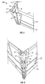
- each clip 26 comprising a pair of arms, each having an parallel inner and an outer portions 27,29 which are interconnected at their respective outer ends and are arranged to respectively lie in face-to-face registration with the front and rear surface of respective flanges 32 of the corner bead member.
- the inner ends of the inner portions 27 of the arms are interconnected by a curved corner formation 28, although a similar nose to the nose 18 of the first embodiment may be provided.
- Each clip 26 is formed of spring steel and can be attached to the corner bead 23 by pulling the outer portions 29 of the arms apart, so that the clip is w-shaped in configuration. The open arms of the clip can then be engaged over respective flanges 32 of the corner bead 23, so that the clip embraces the latter.
- Complementary inter-engaging formations may be provided on the inner and/or outer portions 27,29 for engaging each other through apertures 25 formed in the flanges 32 of the corner bead 23.
- the clips of the embodiment of Figures 7 and 8 are useful in circumstances where the angle bead 23 does not have a hollow nose with which the clip can be engaged.
- a corner bead assembly in accordance with this invention can be quickly and easily applied to external corners formed between walls of a wide range of materials.
Landscapes
- Engineering & Computer Science (AREA)
- Architecture (AREA)
- Civil Engineering (AREA)
- Structural Engineering (AREA)
- Finishing Walls (AREA)
- Clamps And Clips (AREA)
- Connection Of Plates (AREA)
Claims (9)
- Ensemble baguette d'angle (10) comprenant un élément formant baguette d'angle (11) ayant une paire de rebords allongés (12) s'étendant de manière longitudinale, qui sont montés de manière sensiblement perpendiculaire entre eux et qui ont des surfaces avant opposées et des surfaces arrière dirigées vers l'extérieur, les rebords (12) s'étendant vers l'avant à partir d'une formation d'angle (13) s'étendant de manière longitudinale, l'ensemble (10) comprenant en outre une pluralité d'attaches (16) montées sur l'avant de l'élément formant baguette d'angle (11) dans des positions longitudinales sélectives respectives sur ce dernier, chaque attache (16) comprenant une paire de bras (17) montés de manière sensiblement perpendiculaire entre eux, les surfaces arrière des bras (17) étant alignées face à face par rapport aux surfaces avant respectives des rebords (12) de la partie de corps, caractérisé en ce que chaque bras (17) comprend une pluralité d'ardillons (20) sur sa surface avant, les extrémités externes (19) des bras (17) des attaches (16) étant agencées pour se mettre en prise sur les bords latéraux longitudinaux opposés respectifs des rebords (12) respectifs de l'élément formant baguette d'angle (11).
- Ensemble baguette d'angle (10) selon la revendication 1, dans lequel les attaches (16) sont montées de manière coulissante sur l'élément formant baguette d'angle (11).
- Ensemble baguette d'angle (10) selon les revendications 1 ou 2, dans lequel les bras (17) de chaque attache (16) comprennent des parties interne et externe (27, 29) généralement parallèles interconnectées au niveau de leurs extrémités externes respectives et agencées pour être respectivement alignées face à face avec les surfaces avant et arrière des rebords (12) respectifs de l'élément formant baguette d'angle (11), les extrémités internes des parties internes des bras (17) de chaque attache (16) étant interconnectées.
- Ensemble baguette d'angle (10) selon la revendication 3, dans lequel les parties de bras interne et externe (27, 29) sont agencées pour se mettre en prise à travers des ouvertures (15) formées dans les rebords (12) de l'élément formant baguette d'angle (11).
- Ensemble baguette d'angle (10) selon les revendications 3 ou 4, dans lequel les attaches (16) sont formées avec un matériau élastiquement souple qui permet aux parties de bras interne et externe (27, 29) d'être séparées lorsque l'on met en prise les attaches (16) avec l'élément formant baguette d'angle (11).
- Ensemble baguette d'angle (10) selon l'une quelconque des revendications précédentes, dans lequel ladite formation d'angle comprend un nez (13) définissant un canal (14) qui s'étend longitudinalement par rapport au nez (13) sur la surface avant de l'élément formant baguette d'angle (11), les attaches (16) étant montées de manière coulissante sur le canal (14).
- Ensemble baguette d'angle (10) selon l'une quelconque des revendications précédentes, dans lequel les attaches (16) sont formées à partir de métal.
- Procédé pour poser une baguette d'angle (11) sur un angle externe formé entre deux surfaces de paroi, le procédé comprenant les étapes consistant à :a) prévoir un élément formant baguette d'angle (11) ayant une paire de rebords allongés (12) s'étendant de manière longitudinale qui sont montés de manière sensiblement perpendiculaire entre eux et qui ont des surfaces avant opposées et des surfaces arrière dirigées vers l'extérieur, les rebords (12) s'étendant vers l'avant à partir d'un nez (13) s'étendant de manière longitudinale;b) prévoir une pluralité d'attaches (16), chaque attache (16) comprenant une paire de bras (17) montés de manière sensiblement perpendiculaire entre eux et une pluralité d'ardillons (20) sur la surface avant de chaque bras (17) ;c) monter chaque attache (16) sur l'avant de l'élément formant baguette d'angle (11) dans des positions longitudinales sélectives respectives sur ce dernier pour s'aligner avec des régions respectives des surfaces de paroi, de sorte que les surfaces arrière des bras (17) sont alignées face à face avec des surfaces avant respectives des rebords (12) de l'élément formant baguette d'angle (11) ;d) positionner l'ensemble baguette d'angle (10) sur ledit angle de sorte que lesdits rebords (12) sont positionnés contre les surfaces de paroi respectives ; caractérisé en ce que ladite étape de montage comprend en outre l'étape consistant à :e) monter chaque attache (16) sur l'avant de l'élément formant baguette d'angle (11) de sorte que les extrémités externes (19) des bras (17) de l'attache (16) se mettent en prise sur des bords latéraux longitudinaux opposés respectifs des rebords (12) respectifs de l'élément formant baguette d'angle (11); et le procédé comprenant en outre l'étape consistant à :f) comprimer l'ensemble baguette d'angle (10) contre ledit angle de sorte que les ardillons (20) desdites attaches (16) saisissent respectivement lesdites régions sélectionnées des surfaces de paroi.
- Procédé selon la revendication 8, dans lequel la position d'au moins l'une des attaches (16) est ajustée avant ladite étape de positionnement en la faisant coulisser longitudinalement par rapport à l'élément formant baguette d'angle (11).
Applications Claiming Priority (2)
| Application Number | Priority Date | Filing Date | Title |
|---|---|---|---|
| GB0515314A GB2430697B (en) | 2005-07-26 | 2005-07-26 | Corner bead assembly |
| PCT/GB2006/050218 WO2007012897A1 (fr) | 2005-07-26 | 2006-07-20 | Ensemble baguette d’angle |
Publications (2)
| Publication Number | Publication Date |
|---|---|
| EP1907649A1 EP1907649A1 (fr) | 2008-04-09 |
| EP1907649B1 true EP1907649B1 (fr) | 2013-03-20 |
Family
ID=34976599
Family Applications (1)
| Application Number | Title | Priority Date | Filing Date |
|---|---|---|---|
| EP06765367A Not-in-force EP1907649B1 (fr) | 2005-07-26 | 2006-07-20 | Ensemble baguette d'angle et son procédé de pose |
Country Status (4)
| Country | Link |
|---|---|
| EP (1) | EP1907649B1 (fr) |
| AT (1) | ATE552392T1 (fr) |
| GB (1) | GB2430697B (fr) |
| WO (1) | WO2007012897A1 (fr) |
Cited By (1)
| Publication number | Priority date | Publication date | Assignee | Title |
|---|---|---|---|---|
| US10156066B2 (en) | 2017-05-11 | 2018-12-18 | Calaco Solutions Ltd. | Corner bead clip for attaching to steel members |
Families Citing this family (25)
| Publication number | Priority date | Publication date | Assignee | Title |
|---|---|---|---|---|
| GB2472108B (en) * | 2009-08-27 | 2011-07-13 | Budha Singh Dhinjan | Wall bead |
| AU2014203021B2 (en) * | 2013-06-04 | 2017-09-14 | Renset Services Pty Ltd | Angle bead clip |
| WO2017021813A2 (fr) | 2015-07-23 | 2017-02-09 | Mahmoud Meribout | Système et procédé de mesure de débit en temps réel dans des pipelines à l'aide d'imagerie thz |
| USD792610S1 (en) | 2015-08-28 | 2017-07-18 | Clarkwestern Dietrich Building Systems Llc | Control joint with metal lath attachment feature |
| USD792609S1 (en) | 2015-08-28 | 2017-07-18 | Clarkwestern Dietrich Building Systems Llc | Casing bead with metal lath attachment feature |
| USD800346S1 (en) | 2016-02-05 | 2017-10-17 | Clarkwestern Dietrich Building Systems Llc | Control joint with ribbed flanges |
| USD800345S1 (en) | 2016-02-05 | 2017-10-17 | Clarkwestern Dietrich Building Systems | Channel reveal with ribbed flanges |
| USD800921S1 (en) | 2016-02-05 | 2017-10-24 | Clarkwestern Dietrich Building Systems Llc | Framing accessory with a ribbed flange |
| USD800344S1 (en) | 2016-02-05 | 2017-10-17 | Clarkwestern Dietrich Building Systems Llc | Casing bead with a ribbed flange |
| CZ2016286A3 (cs) * | 2016-05-14 | 2017-08-16 | Rostislav PĂka | Montážní deformační kotva |
| USD841833S1 (en) | 2017-01-09 | 2019-02-26 | Clarkwestern Dietrich Building Systems Llc | Channel reveal with ribbed and perforated flanges |
| USD843015S1 (en) | 2017-01-09 | 2019-03-12 | Clarkwestern Dietrich Building Systems Llc | Framing accessory with a ribbed and perforated flange |
| USD842497S1 (en) | 2017-01-09 | 2019-03-05 | Clarkwestern Dietrich Building Systems Llc | Control joint with ribbed and perforated flanges |
| USD842496S1 (en) | 2017-01-09 | 2019-03-05 | Clarkwestern Dietrich Building Systems Llc | Casing bead with a ribbed and perforated flange |
| IL253345B (en) * | 2017-07-06 | 2021-02-28 | Ber Ilan | Adjustable clamp for plaster corners |
| USD904649S1 (en) | 2019-09-25 | 2020-12-08 | Clarkwestern Dietrich Building Systems Llc | Weep screed |
| USD1026252S1 (en) | 2020-11-12 | 2024-05-07 | Clarkwestern Dietrich Building Systems Llc | Control joint |
| US11885138B2 (en) | 2020-11-12 | 2024-01-30 | Clarkwestern Dietrich Building Systems Llc | Control joint |
| USD1115066S1 (en) | 2022-12-20 | 2026-02-24 | Clarkwestern Dietrich Building Systems Llc | Vent screed |
| USD1114999S1 (en) | 2023-05-05 | 2026-02-24 | Clarkwestern Dietrich Building Systems Llc | Drainage screed |
| USD1115061S1 (en) | 2023-05-05 | 2026-02-24 | Clarkwestern Dietrich Building Systems Llc | Vent screed |
| USD1115062S1 (en) | 2023-08-21 | 2026-02-24 | Clarkwestern Dietrich Building Systems Llc | Vent screed |
| USD1115064S1 (en) | 2023-08-21 | 2026-02-24 | Clarkwestern Dietrich Building Systems Llc | Weep screed |
| USD1115065S1 (en) | 2023-08-21 | 2026-02-24 | Clarkwestern Dietrich Building Systems Llc | Weep screed |
| USD1115063S1 (en) | 2023-08-21 | 2026-02-24 | Clarkwestern Dietrich Building Systems Llc | Vent screed |
Family Cites Families (11)
| Publication number | Priority date | Publication date | Assignee | Title |
|---|---|---|---|---|
| US1106730A (en) | 1913-09-02 | 1914-08-11 | Bostwick Steel Lath Company | Corner bead or strip. |
| US1430508A (en) * | 1920-10-25 | 1922-09-26 | Johnson John | Corner bead |
| US1686278A (en) * | 1927-09-10 | 1928-10-02 | Kauffman Roger | Clip for beading construction |
| GB424208A (en) * | 1933-08-18 | 1935-02-18 | Jesse Bertram Blakey | An improved plasterers' metallic angle bead for walls |
| US2859445A (en) * | 1955-03-09 | 1958-11-11 | Robert C Larrabee | Corner bead applying apparatus |
| GB1090157A (en) * | 1965-07-16 | 1967-11-08 | Expanded Metal | Improvements in beads for protecting plaster board and the like |
| US3717968A (en) * | 1970-07-16 | 1973-02-27 | Specialties Const | Surface-mounted wall guards |
| DE3344135A1 (de) * | 1983-12-07 | 1985-06-20 | Heinz 7850 Lörrach Krieger | Befestigungselement fuer innenputz-eckleisten |
| US4876837A (en) * | 1988-08-22 | 1989-10-31 | Usg Interiors, Inc. | Corner bead structure |
| US5778617A (en) * | 1995-10-27 | 1998-07-14 | Free; Gerald R. | Press-on corner bead |
| AU3987699A (en) * | 1998-05-13 | 1999-11-29 | John S. Conboy | Composite drywall corner bead and method of making same |
-
2005
- 2005-07-26 GB GB0515314A patent/GB2430697B/en not_active Expired - Lifetime
-
2006
- 2006-07-20 EP EP06765367A patent/EP1907649B1/fr not_active Not-in-force
- 2006-07-20 AT AT06765367T patent/ATE552392T1/de active
- 2006-07-20 WO PCT/GB2006/050218 patent/WO2007012897A1/fr not_active Ceased
Cited By (1)
| Publication number | Priority date | Publication date | Assignee | Title |
|---|---|---|---|---|
| US10156066B2 (en) | 2017-05-11 | 2018-12-18 | Calaco Solutions Ltd. | Corner bead clip for attaching to steel members |
Also Published As
| Publication number | Publication date |
|---|---|
| ATE552392T1 (de) | 2012-04-15 |
| WO2007012897A1 (fr) | 2007-02-01 |
| EP1907649A1 (fr) | 2008-04-09 |
| GB2430697A (en) | 2007-04-04 |
| GB0515314D0 (en) | 2005-08-31 |
| GB2430697B (en) | 2008-01-30 |
Similar Documents
| Publication | Publication Date | Title |
|---|---|---|
| EP1907649B1 (fr) | Ensemble baguette d'angle et son procédé de pose | |
| CA2771711C (fr) | Protection d'arete de mur | |
| US5203132A (en) | Wall assembly | |
| US7698867B1 (en) | Siding trim clip with triangular gripping pattern | |
| US12054953B2 (en) | Grooved cornerbead | |
| EP3330449A1 (fr) | Composant de construction | |
| EP0869231B1 (fr) | Système d'ancrage pour panneaux, notamment panneaux pour façades ventilées | |
| US2742778A (en) | Furring devices | |
| US4569172A (en) | Interior corner construction for wallboard, ceiling and partition panel assemblies, and backer clips therefor | |
| US20060053734A1 (en) | Hide-a-nail | |
| EP4004303B1 (fr) | Baguette pour plâtre | |
| EP4204640B1 (fr) | Système de fixation de lamelles et procédé d'installation d'une lamelle | |
| JPH03110252A (ja) | タイルのとり付け工法 | |
| JPH076303Y2 (ja) | 壁板の取付け構造 | |
| CA3007164A1 (fr) | Une composante de batiment | |
| GB2556161A (en) | Plaster bead | |
| AU784268B2 (en) | Mounting bracket | |
| JPH0446017Y2 (fr) | ||
| JP2991449B2 (ja) | 硬質壁材の取付構造 | |
| JP2003003613A (ja) | 耐風クリップ及び屋根材の施工方法 | |
| GB2421253A (en) | Fixing clip | |
| NZ514150A (en) | Mounting bracket | |
| JPS58541A (ja) | 建築材の取付金具 | |
| JP2001193225A (ja) | 瓦固定金具とこの金具を用いた瓦止めの施工方法 | |
| JPH02296944A (ja) | 目地充填体 |
Legal Events
| Date | Code | Title | Description |
|---|---|---|---|
| PUAI | Public reference made under article 153(3) epc to a published international application that has entered the european phase |
Free format text: ORIGINAL CODE: 0009012 |
|
| 17P | Request for examination filed |
Effective date: 20080215 |
|
| AK | Designated contracting states |
Kind code of ref document: A1 Designated state(s): AT BE BG CH CY CZ DE DK EE ES FI FR GB GR HU IE IS IT LI LT LU LV MC NL PL PT RO SE SI SK TR |
|
| 17Q | First examination report despatched |
Effective date: 20091008 |
|
| GRAP | Despatch of communication of intention to grant a patent |
Free format text: ORIGINAL CODE: EPIDOSNIGR1 |
|
| RTI1 | Title (correction) |
Free format text: CORNER BEAD ASSEMBLY AND METHOD OF APPLYING THE SAME |
|
| DAX | Request for extension of the european patent (deleted) | ||
| GRAS | Grant fee paid |
Free format text: ORIGINAL CODE: EPIDOSNIGR3 |
|
| GRAA | (expected) grant |
Free format text: ORIGINAL CODE: 0009210 |
|
| PUAC | Information related to the publication of a b1 document modified or deleted |
Free format text: ORIGINAL CODE: 0009299EPPU |
|
| AK | Designated contracting states |
Kind code of ref document: B1 Designated state(s): AT BE BG CH CY CZ DE DK EE ES FI FR GB GR HU IE IS IT LI LT LU LV MC NL PL PT RO SE SI SK TR |
|
| REG | Reference to a national code |
Ref country code: GB Ref legal event code: FG4D |
|
| DB1 | Publication of patent cancelled | ||
| REG | Reference to a national code |
Ref country code: CH Ref legal event code: PK Free format text: BERICHTIGUNG (ENGL.) Ref country code: CH Ref legal event code: EP |
|
| REG | Reference to a national code |
Ref country code: AT Ref legal event code: REF Ref document number: 552392 Country of ref document: AT Kind code of ref document: T Effective date: 20120415 |
|
| REG | Reference to a national code |
Ref country code: NL Ref legal event code: GRER Effective date: 20120411 |
|
| REG | Reference to a national code |
Ref country code: IE Ref legal event code: FG4D |
|
| REG | Reference to a national code |
Ref country code: DE Ref legal event code: R096 Ref document number: 602006028619 Country of ref document: DE Effective date: 20120531 |
|
| REG | Reference to a national code |
Ref country code: DE Ref legal event code: R409 Ref document number: 602006028619 Country of ref document: DE |
|
| GRAA | (expected) grant |
Free format text: ORIGINAL CODE: 0009210 |
|
| AK | Designated contracting states |
Kind code of ref document: B1 Designated state(s): AT BE BG CH CY CZ DE DK EE ES FI FR GB GR HU IE IS IT LI LT LU LV MC NL PL PT RO SE SI SK TR |
|
| REG | Reference to a national code |
Ref country code: GB Ref legal event code: FG4D |
|
| REG | Reference to a national code |
Ref country code: CH Ref legal event code: EP Ref country code: CH Ref legal event code: PK Free format text: DIE ERTEILUNG VOM 04.04.2012 WURDE VOM EPA WIDERRUFEN |
|
| REG | Reference to a national code |
Ref country code: NL Ref legal event code: VDEP Effective date: 20130320 |
|
| PG25 | Lapsed in a contracting state [announced via postgrant information from national office to epo] |
Ref country code: NL Free format text: LAPSE BECAUSE OF FAILURE TO SUBMIT A TRANSLATION OF THE DESCRIPTION OR TO PAY THE FEE WITHIN THE PRESCRIBED TIME-LIMIT Effective date: 20130320 |
|
| PG25 | Lapsed in a contracting state [announced via postgrant information from national office to epo] |
Ref country code: LT Free format text: LAPSE BECAUSE OF FAILURE TO SUBMIT A TRANSLATION OF THE DESCRIPTION OR TO PAY THE FEE WITHIN THE PRESCRIBED TIME-LIMIT Effective date: 20130320 |
|
| REG | Reference to a national code |
Ref country code: LT Ref legal event code: MG4D |
|
| PG25 | Lapsed in a contracting state [announced via postgrant information from national office to epo] |
Ref country code: LV Free format text: LAPSE BECAUSE OF FAILURE TO SUBMIT A TRANSLATION OF THE DESCRIPTION OR TO PAY THE FEE WITHIN THE PRESCRIBED TIME-LIMIT Effective date: 20130320 Ref country code: SI Free format text: LAPSE BECAUSE OF FAILURE TO SUBMIT A TRANSLATION OF THE DESCRIPTION OR TO PAY THE FEE WITHIN THE PRESCRIBED TIME-LIMIT Effective date: 20130320 |
|
| REG | Reference to a national code |
Ref country code: DE Ref legal event code: R119 Ref document number: 602006028619 Country of ref document: DE Effective date: 20130201 |
|
| PG25 | Lapsed in a contracting state [announced via postgrant information from national office to epo] |
Ref country code: BE Free format text: LAPSE BECAUSE OF FAILURE TO SUBMIT A TRANSLATION OF THE DESCRIPTION OR TO PAY THE FEE WITHIN THE PRESCRIBED TIME-LIMIT Effective date: 20130320 |
|
| PG25 | Lapsed in a contracting state [announced via postgrant information from national office to epo] |
Ref country code: CZ Free format text: LAPSE BECAUSE OF FAILURE TO SUBMIT A TRANSLATION OF THE DESCRIPTION OR TO PAY THE FEE WITHIN THE PRESCRIBED TIME-LIMIT Effective date: 20130320 Ref country code: EE Free format text: LAPSE BECAUSE OF FAILURE TO SUBMIT A TRANSLATION OF THE DESCRIPTION OR TO PAY THE FEE WITHIN THE PRESCRIBED TIME-LIMIT Effective date: 20130320 Ref country code: SK Free format text: LAPSE BECAUSE OF FAILURE TO SUBMIT A TRANSLATION OF THE DESCRIPTION OR TO PAY THE FEE WITHIN THE PRESCRIBED TIME-LIMIT Effective date: 20130320 |
|
| REG | Reference to a national code |
Ref country code: DE Ref legal event code: R409 Ref document number: 602006028619 Country of ref document: DE |
|
| PG25 | Lapsed in a contracting state [announced via postgrant information from national office to epo] |
Ref country code: PL Free format text: LAPSE BECAUSE OF FAILURE TO SUBMIT A TRANSLATION OF THE DESCRIPTION OR TO PAY THE FEE WITHIN THE PRESCRIBED TIME-LIMIT Effective date: 20130320 |
|
| PLBE | No opposition filed within time limit |
Free format text: ORIGINAL CODE: 0009261 |
|
| STAA | Information on the status of an ep patent application or granted ep patent |
Free format text: STATUS: NO OPPOSITION FILED WITHIN TIME LIMIT |
|
| PG25 | Lapsed in a contracting state [announced via postgrant information from national office to epo] |
Ref country code: DK Free format text: LAPSE BECAUSE OF FAILURE TO SUBMIT A TRANSLATION OF THE DESCRIPTION OR TO PAY THE FEE WITHIN THE PRESCRIBED TIME-LIMIT Effective date: 20130320 |
|
| 26N | No opposition filed |
Effective date: 20140102 |
|
| PG25 | Lapsed in a contracting state [announced via postgrant information from national office to epo] |
Ref country code: IT Free format text: LAPSE BECAUSE OF FAILURE TO SUBMIT A TRANSLATION OF THE DESCRIPTION OR TO PAY THE FEE WITHIN THE PRESCRIBED TIME-LIMIT Effective date: 20130320 Ref country code: MC Free format text: LAPSE BECAUSE OF FAILURE TO SUBMIT A TRANSLATION OF THE DESCRIPTION OR TO PAY THE FEE WITHIN THE PRESCRIBED TIME-LIMIT Effective date: 20130320 |
|
| REG | Reference to a national code |
Ref country code: CH Ref legal event code: PL |
|
| PG25 | Lapsed in a contracting state [announced via postgrant information from national office to epo] |
Ref country code: LI Free format text: LAPSE BECAUSE OF NON-PAYMENT OF DUE FEES Effective date: 20130731 Ref country code: CH Free format text: LAPSE BECAUSE OF NON-PAYMENT OF DUE FEES Effective date: 20130731 |
|
| PG25 | Lapsed in a contracting state [announced via postgrant information from national office to epo] |
Ref country code: ES Free format text: LAPSE BECAUSE OF FAILURE TO SUBMIT A TRANSLATION OF THE DESCRIPTION OR TO PAY THE FEE WITHIN THE PRESCRIBED TIME-LIMIT Effective date: 20120715 |
|
| PG25 | Lapsed in a contracting state [announced via postgrant information from national office to epo] |
Ref country code: ES Free format text: LAPSE BECAUSE OF FAILURE TO SUBMIT A TRANSLATION OF THE DESCRIPTION OR TO PAY THE FEE WITHIN THE PRESCRIBED TIME-LIMIT Effective date: 20130320 |
|
| PG25 | Lapsed in a contracting state [announced via postgrant information from national office to epo] |
Ref country code: RO Free format text: LAPSE BECAUSE OF FAILURE TO SUBMIT A TRANSLATION OF THE DESCRIPTION OR TO PAY THE FEE WITHIN THE PRESCRIBED TIME-LIMIT Effective date: 20130320 |
|
| PG25 | Lapsed in a contracting state [announced via postgrant information from national office to epo] |
Ref country code: CY Free format text: LAPSE BECAUSE OF FAILURE TO SUBMIT A TRANSLATION OF THE DESCRIPTION OR TO PAY THE FEE WITHIN THE PRESCRIBED TIME-LIMIT Effective date: 20130320 Ref country code: TR Free format text: LAPSE BECAUSE OF FAILURE TO SUBMIT A TRANSLATION OF THE DESCRIPTION OR TO PAY THE FEE WITHIN THE PRESCRIBED TIME-LIMIT Effective date: 20130320 |
|
| PG25 | Lapsed in a contracting state [announced via postgrant information from national office to epo] |
Ref country code: LU Free format text: LAPSE BECAUSE OF NON-PAYMENT OF DUE FEES Effective date: 20130320 Ref country code: BG Free format text: LAPSE BECAUSE OF FAILURE TO SUBMIT A TRANSLATION OF THE DESCRIPTION OR TO PAY THE FEE WITHIN THE PRESCRIBED TIME-LIMIT Effective date: 20130320 Ref country code: HU Free format text: LAPSE BECAUSE OF FAILURE TO SUBMIT A TRANSLATION OF THE DESCRIPTION OR TO PAY THE FEE WITHIN THE PRESCRIBED TIME-LIMIT; INVALID AB INITIO Effective date: 20060720 Ref country code: FI Free format text: LAPSE BECAUSE OF FAILURE TO SUBMIT A TRANSLATION OF THE DESCRIPTION OR TO PAY THE FEE WITHIN THE PRESCRIBED TIME-LIMIT Effective date: 20130320 |
|
| REG | Reference to a national code |
Ref country code: FR Ref legal event code: PLFP Year of fee payment: 10 |
|
| PG25 | Lapsed in a contracting state [announced via postgrant information from national office to epo] |
Ref country code: SE Free format text: LAPSE BECAUSE OF NON-PAYMENT OF DUE FEES Effective date: 20130320 Ref country code: GR Free format text: LAPSE BECAUSE OF NON-PAYMENT OF DUE FEES Effective date: 20130320 |
|
| PGFP | Annual fee paid to national office [announced via postgrant information from national office to epo] |
Ref country code: IE Payment date: 20150810 Year of fee payment: 10 Ref country code: DE Payment date: 20150804 Year of fee payment: 10 |
|
| PGFP | Annual fee paid to national office [announced via postgrant information from national office to epo] |
Ref country code: FR Payment date: 20150731 Year of fee payment: 10 |
|
| PG25 | Lapsed in a contracting state [announced via postgrant information from national office to epo] |
Ref country code: PT Free format text: LAPSE BECAUSE OF FAILURE TO SUBMIT A TRANSLATION OF THE DESCRIPTION OR TO PAY THE FEE WITHIN THE PRESCRIBED TIME-LIMIT Effective date: 20130320 |
|
| PG25 | Lapsed in a contracting state [announced via postgrant information from national office to epo] |
Ref country code: AT Free format text: LAPSE BECAUSE OF NON-PAYMENT OF DUE FEES Effective date: 20140731 |
|
| PG25 | Lapsed in a contracting state [announced via postgrant information from national office to epo] |
Ref country code: IS Free format text: LAPSE BECAUSE OF FAILURE TO SUBMIT A TRANSLATION OF THE DESCRIPTION OR TO PAY THE FEE WITHIN THE PRESCRIBED TIME-LIMIT Effective date: 20130320 |
|
| REG | Reference to a national code |
Ref country code: DE Ref legal event code: R119 Ref document number: 602006028619 Country of ref document: DE |
|
| PG25 | Lapsed in a contracting state [announced via postgrant information from national office to epo] |
Ref country code: FR Free format text: LAPSE BECAUSE OF NON-PAYMENT OF DUE FEES Effective date: 20160801 |
|
| REG | Reference to a national code |
Ref country code: FR Ref legal event code: ST Effective date: 20170331 |
|
| REG | Reference to a national code |
Ref country code: IE Ref legal event code: MM4A |
|
| PG25 | Lapsed in a contracting state [announced via postgrant information from national office to epo] |
Ref country code: IE Free format text: LAPSE BECAUSE OF NON-PAYMENT OF DUE FEES Effective date: 20160720 |
|
| PG25 | Lapsed in a contracting state [announced via postgrant information from national office to epo] |
Ref country code: DE Free format text: LAPSE BECAUSE OF NON-PAYMENT OF DUE FEES Effective date: 20170201 |
|
| PGFP | Annual fee paid to national office [announced via postgrant information from national office to epo] |
Ref country code: GB Payment date: 20190712 Year of fee payment: 14 |
|
| GBPC | Gb: european patent ceased through non-payment of renewal fee |
Effective date: 20200720 |
|
| PG25 | Lapsed in a contracting state [announced via postgrant information from national office to epo] |
Ref country code: GB Free format text: LAPSE BECAUSE OF NON-PAYMENT OF DUE FEES Effective date: 20200720 |