EP1907737B1 - Flüssigkeitsströmungsventil mit einer bistabilen elektromagnetischen steueranordnung - Google Patents
Flüssigkeitsströmungsventil mit einer bistabilen elektromagnetischen steueranordnung Download PDFInfo
- Publication number
- EP1907737B1 EP1907737B1 EP06777871A EP06777871A EP1907737B1 EP 1907737 B1 EP1907737 B1 EP 1907737B1 EP 06777871 A EP06777871 A EP 06777871A EP 06777871 A EP06777871 A EP 06777871A EP 1907737 B1 EP1907737 B1 EP 1907737B1
- Authority
- EP
- European Patent Office
- Prior art keywords
- armature
- valve
- core
- magnetic pole
- stable position
- Prior art date
- Legal status (The legal status is an assumption and is not a legal conclusion. Google has not performed a legal analysis and makes no representation as to the accuracy of the status listed.)
- Active
Links
Images

Classifications
-
- F—MECHANICAL ENGINEERING; LIGHTING; HEATING; WEAPONS; BLASTING
- F16—ENGINEERING ELEMENTS AND UNITS; GENERAL MEASURES FOR PRODUCING AND MAINTAINING EFFECTIVE FUNCTIONING OF MACHINES OR INSTALLATIONS; THERMAL INSULATION IN GENERAL
- F16K—VALVES; TAPS; COCKS; ACTUATING-FLOATS; DEVICES FOR VENTING OR AERATING
- F16K31/00—Actuating devices; Operating means; Releasing devices
- F16K31/12—Actuating devices; Operating means; Releasing devices actuated by fluid
- F16K31/36—Actuating devices; Operating means; Releasing devices actuated by fluid in which fluid from the circuit is constantly supplied to the fluid motor
- F16K31/40—Actuating devices; Operating means; Releasing devices actuated by fluid in which fluid from the circuit is constantly supplied to the fluid motor with electrically-actuated member in the discharge of the motor
- F16K31/402—Actuating devices; Operating means; Releasing devices actuated by fluid in which fluid from the circuit is constantly supplied to the fluid motor with electrically-actuated member in the discharge of the motor acting on a diaphragm
- F16K31/404—Actuating devices; Operating means; Releasing devices actuated by fluid in which fluid from the circuit is constantly supplied to the fluid motor with electrically-actuated member in the discharge of the motor acting on a diaphragm the discharge being effected through the diaphragm and being blockable by an electrically-actuated member making contact with the diaphragm
-
- F—MECHANICAL ENGINEERING; LIGHTING; HEATING; WEAPONS; BLASTING
- F16—ENGINEERING ELEMENTS AND UNITS; GENERAL MEASURES FOR PRODUCING AND MAINTAINING EFFECTIVE FUNCTIONING OF MACHINES OR INSTALLATIONS; THERMAL INSULATION IN GENERAL
- F16K—VALVES; TAPS; COCKS; ACTUATING-FLOATS; DEVICES FOR VENTING OR AERATING
- F16K31/00—Actuating devices; Operating means; Releasing devices
- F16K31/02—Actuating devices; Operating means; Releasing devices electric; magnetic
- F16K31/06—Actuating devices; Operating means; Releasing devices electric; magnetic using a magnet, e.g. diaphragm valves, cutting off by means of a liquid
- F16K31/08—Actuating devices; Operating means; Releasing devices electric; magnetic using a magnet, e.g. diaphragm valves, cutting off by means of a liquid using a permanent magnet
- F16K31/082—Actuating devices; Operating means; Releasing devices electric; magnetic using a magnet, e.g. diaphragm valves, cutting off by means of a liquid using a permanent magnet using a electromagnet and a permanent magnet
Definitions
- the present invention relates to a liquid flow on-off valve with a bistable electromagnetic control assembly.
- the present invention relates to a membrane-type liquid flow on-off valve with a bistable electromagnetic control assembly, wherein the membrane has a liquid flow orifice, so that the pressure of the liquid itself keeps the valve closed.
- Patent Application EP 1,416,207 A valve of this type is illustrated in Patent Application EP 1,416,207 . More specifically, the liquid flow on-off valve with a bistable electromagnetic control assembly described in Patent Application EP 1, 416,207 comprises an auxiliary channel; and an auxiliary shutter, which is activated by the electromagnetic control assembly to selectively cut off flow along the auxiliary channel.
- the electromagnetic control assembly comprises a yoke; a coil; a core inside the coil; an armature movable between a first stable position contacting the core, and a second stable position a given distance from the core; and a permanent magnet for generating electromagnetic flux along the yoke, the core, and the armature.
- the coil is supplied with pulses of opposite polarity.
- a pulse of a first polarity moves the armature into the first stable position, in which it is held by the electromagnetic flux generated by the permanent magnet located directly over the core.
- a pulse of a second polarity opposite the first, moves the armature into the second stable position, in which it is held by a compression spring located between the core and the armature.
- the force exerted by the spring must be calibrated precisely for the armature to be held contacting the core by the force of the magnetic flux generated by the permanent magnet, and, at the same time, must be capable of overcoming the force of the magnetic flux generated by the permanent magnet, when the armature is in the second stable position.
- liquid flow on-off valve with a bistable electromagnetic control assembly is disclosed in EP 0,717,220 A1 , according to which the yoke comprises a first portion fitted about the coil and defining, in use, a first and a second magnetic pole; and a second portion separated from the first portion by a permanent magnet and defining a third magnetic pole.
- the first, second, and third magnetic pole are arranged successively along said axis, from the core towards the armature.
- the above-identified liquid flow on-off valve still needs a spring to keep the valve in one of the two stable positions.
- a liquid flow on-off valve with a bistable electromagnetic control assembly the valve being characterized in that the first magnetic pole faces the core, the second magnetic pole faces the armature, and the third magnetic pole faces neither the core nor the armature so that the first and second stable position are maintained solely by the magnetic flux generated by the permanent magnet and conducted selectively through the yoke, the core, and the armature as a function of the position of the armature
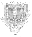
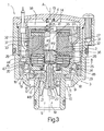
- number 1 indicates as a whole a liquid flow on-off valve with a bistable electromagnetic control assembly 2, so that valve 1 is kept open (first stable position, Figure 2 ) or closed (second stable position, Figure 1 ) with no electric power to electromagnetic control assembly 2.
- Valve 1 extends along an axis A, and comprises a valve body 3; a cover 4 fitted to valve body 3; a shutter 5 movable along axis A; and a membrane 6 fixed to valve body 3 and shutter 5.
- Shutter 5 is integral with a cup-shaped body 7 housing electromagnetic control assembly 2, which therefore moves along axis A together with shutter 5.
- Valve body 3 comprises a lateral wall 8; a bottom wall 9 (the terms “lateral” and “bottom” as used herein refer solely to the way in which the valve is shown in the accompanying drawings, it being understood that valve 1 may be oriented any way); and a tube 10 projecting from bottom wall 9.. Openings 11 are formed in bottom wall 9 and define a liquid inlet channel 12, while tube 10 defines an outlet channel 13. Lateral wall 8 is closed by cover 4, which defines, inside valve body 3, a gap 14 communicating at all times with inlet channel 12, regardless of the operating position of valve 1.
- a compression spring 15 is located between cover 4 and assembly 2, and pushes electromagnetic control assembly 2, cup-shaped body 7 and shutter 5, and membrane 6 onto the end of tube 10 to prevent liquid flow from inlet channel 12 to outlet channel 13 ( Figure 1 ).
- Membrane 6 is annular, and comprises an outer seal 16 fixed to valve body 3, between lateral wall 8 and bottom wall 9; and an inner seal 17 fixed to shutter 5 and, in the example shown, housed inside a cavity 18 formed between shutter 5 and cup-shaped body 7, which in fact are formed in one piece.
- Membrane 6 also has three holes 19, which are equally spaced about axis A, are located at corresponding openings 11 at one end, and are connected to one another, at the other end, by an annular channel formed in membrane 6.
- the annular channel is connected to a channel 20 formed in cup-shaped body 7 and in turn connected to gap 14, so that gap 14 in valve body 3 communicates with inlet channel 12, regardless of the operating position.of valve 1.
- Shutter 5 comprises a cylindrical body 21, which slides along axis A inside tube 10; and a central tube 22 defining a channel 23, which can be selectively opened to connect outlet channel 13 to gap 14, and therefore to inlet channel 12.
- holes 19, channel 20, gap 14, and channel 23 define an auxiliary channel connecting inlet channel 12 and outlet channel 13, and which can be cut off selectively by an auxiliary shutter 24 controlled by electromagnetic control assembly 2.
- auxiliary shutter 24 is integral with an armature 25 movable along axis A and forming part of electromagnetic control assembly 2, which comprises a cylindrical body 26, of axis A, having two outer annular flanges 27 and 28.
- Cylindrical body 26 is made of insulating material, and is fitted to cup-shaped body 7 with a seal 29 and resin 30 to isolate from the liquid a compartment 31 housing a coil 32, a yoke 33, and a permanent magnet 34.
- Electromagnetic control assembly 2 also comprises a core 35 fixed inside cylindrical body 26 and having a face 36 located along axis A, between flanges 27 and 28. Core 35 and armature 25 are coaxial and housed inside cylindrical body 26.
- Coil 32 surrounds cylindrical body 26, and is housed between flanges 27 and 28 and a cylindrical wall 37 which forms part of yoke 33.
- yoke 33 also comprises a ring 38 located at flange 27, on the opposite side to coil 32, and contacting one end of cylindrical wall 37; a ring 39 contacting flange 28 and the opposite end of cylindrical wall 37; and a ring 40 surrounding cylindrical body 26 and separated from ring 39 by permanent magnet 34.
- Rings 38, 39, 40 are bored disks of ferromagnetic material, the respective inner cylindrical faces 41, 42, 43 of which define respective magnetic poles P1, P2, P3. Magnetic pole P1 contacts core 35 directly, while magnetic poles P2, P3 contact the outer face of cylindrical body 26.
- Magnetic poles P1, P2, P3 are arranged successively along axis A in the direction from core 35 to armature 25. More specifically, the first magnetic pole P1 faces core 35; the second magnetic pole P2 faces armature 25; and the third magnetic pole P3 faces tube 22, and neither core 35 nor armature 25. The distance between magnetic poles P2 and P3 is much smaller than that between magnetic poles P1 and P2.
- the exact position of second magnetic pole P2 along axis A is substantially selected as a function of the length of armature 25 along axis A, and so that, when armature 25 is in the first stable position ( Figure 2 ), the magnetic flux through second magnetic pole P2 is negligible with respect to the magnetic flux generated by permanent magnet 34 through first and third magnetic pole P1 and P3; and, when armature 25 is in the second stable position ( Figure 1 ), the magnetic flux through first magnetic pole P1 is negligible with respect to the magnetic flux generated by the permanent magnet through second and third magnetic pole P2 and P3.
- Permanent magnet 34 is also in the form of a ring (bored disk), is substantially the same thickness as rings 38, 39, 40, but has an inside diameter substantially larger than the inside diameters of rings 38, 39, 40, and an outside diameter substantially equal to the diameter of ring 39.
- Valve 1 in Figure 1 is shown in a second stable position, in which flow between inlet channel 12 and outlet channel 13 is cut off by shutter 5; and flow along the auxiliary channel - defined by gap 14, holes 19 in the membrane, channel 20, and channel 23 - is also cut off by auxiliary shutter 24, which is pressed onto tube 22 by the magnetic flux generated by permanent magnet 24 through magnetic poles P2 and P3 and acting on armature 25.
- auxiliary shutter 24 is pressed onto tube 22 by the magnetic flux generated by permanent magnet 24 through magnetic poles P2 and P3 and acting on armature 25.
- Valve 1 is therefore retained in the first stable position solely by the action of permanent magnet 34.
- a pulse transmitted to coil 32, to generate magnetic flux discordant with respect to that generated by permanent magnet 34, produces magnetic flux through magnetic poles P1 and P2 to detach armature 25 from core 35, while permanent magnet 34 produces magnetic flux between poles P2 and P3 to press armature 25 and auxiliary shutter 24 onto tube 22.
- the predominant magnetic flux is that acting between poles P2 and P3, so that auxiliary shutter 24 is closed, thus closing and maintaining the second stable position of valve 1.
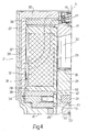
- Valve 1 in Figure 3 substantially differs from the Figure 1 valve as regards certain parts of electromagnetic control assembly 2. More specifically, permanent magnet 34 is replaced by two annular permanent magnets 44 and 45 connected along axis A. Magnetic pole P3 is defined by an L-section ring 46 substantially comprising a portion 47 perpendicular to axis A, and a portion 48 coaxial with axis A and having a face 49 extending about axis A and defining third magnetic pole P3. The magnetic flux generated by the two permanent magnets 44 and 45 is greater than that generated by one magnet 34.
Landscapes
- Engineering & Computer Science (AREA)
- General Engineering & Computer Science (AREA)
- Mechanical Engineering (AREA)
- Physics & Mathematics (AREA)
- Electromagnetism (AREA)
- Magnetically Actuated Valves (AREA)
- Fluid-Driven Valves (AREA)
Claims (15)
- Flüssigkeitsstrom-Schaltventil mit einer bistabilen elektromagnetischen Steueranordnung (2), wobei das Ventil einen Hilfskanal (14, 19, 20, 23); und einen Hilfsverschluss (24), der durch die elektromagnetische Steueranordnung (2) betätigt wird, um den Strom längs des Hilfskanals (14, 19, 20, 23) wahlweise zu unterbrechen, umfasst; wobei die elektromagnetische Steueranordnung (2) ihrerseits ein Joch (33); eine Spule (32), die mit dem Joch (33) zusammenwirkt; einen Kern (35) in der Spule (32); einen Permanentmagneten (34; 44, 45), der mit dem Joch (33) zusammenwirkt; und einen Anker (25), der längs einer Achse (A) zwischen einer ersten stabilen Position, in der er mit dem Kern (35) in Kontakt ist, und einer zweiten stabilen Position, in der sich der Anker (25) in einem Abstand von dem Kern (35) befindet, beweglich ist, umfasst; wobei das Joch (33) einen ersten Abschnitt (37, 38, 39), der um die Spule (32) angebracht ist und im Gebrauch einen ersten und einen zweiten Magnetpol (P1, P2) definiert; und einen zweiten Abschnitt (40; 46), der von dem ersten Abschnitt durch den Permanentmagneten (34; 44, 45) getrennt ist und einen dritten Magnetpol (P3) definiert, umfasst, wobei der erste, der zweite und der dritte Magnetpol (P1, P2, P3) längs der Achse (A) von dem Kern (35) zu dem Anker (25) nacheinander angeordnet sind, wobei das Ventil dadurch gekennzeichnet ist, dass der erste Magnetpol (P1) dem Kern (35) zugewandt ist, der zweite Magnetpol (P2) dem Anker (25) zugewandt ist und der dritte Magnetpol (P3) weder dem Kern (35) noch dem Anker (25) zugewandt ist, so dass die erste und die zweite stabile Position lediglich durch den magnetischen Fluss, der durch den Permanentmagneten (34; 44, 45) erzeugt wird und als Funktion der Position des Ankers (25) wahlweise durch das Joch (33), den Kern (35) und den Anker (25) geleitet wird, aufrechterhalten werden.
- Ventil nach Anspruch 1, dadurch gekennzeichnet, dass der Permanentmagnet (34; 44, 45), der Kern (35), der Anker (25) und das Joch (33) so entworfen sind, dass der magnetische Fluss längs eines ersten Wegs geführt wird, wenn sich der Anker (25) in der ersten stabilen Position befindet, wobei der erste Weg des magnetischen Flusses den Anker (25) in der ersten stabilen Position hält, und längs eines zweiten Wegs geführt wird, wenn sich der Anker (25) in der zweiten stabilen Position befindet, wobei der zweite Weg des magnetischen Flusses den Anker (25) in der zweiten stabilen Position hält.
- Ventil nach Anspruch 1 oder 2, dadurch gekennzeichnet, dass es keine Federn besitzt, um die erste und/oder die zweite stabile Position festzulegen.
- Ventil nach einem der vorhergehenden Ansprüche, dadurch gekennzeichnet, dass sich der Permanentmagnet (34; 44, 45) im Wesentlichen auf einer Höhe mit dem Hilfsverschluss (24) längs der Achse (A) befindet; wobei sich der Hilfsverschluss (24) an dem freien Ende des Ankers (25) befindet.
- Ventil nach einem der vorhergehenden Ansprüche, dadurch gekennzeichnet, dass der Kern (35) längs der Achse (A) eine Länge besitzt, die größer als die Länge des Ankers (25) längs der Achse (A) ist.
- Ventil nach Anspruch 5, dadurch gekennzeichnet, dass die Länge des Kerns (35) im Wesentlichen gleich der eineinhalbfachen Länge des Ankers (25) längs der Achse (A) ist.
- Ventil nach einem der vorhergehenden Ansprüche, dadurch gekennzeichnet, dass der Abstand zwischen dem zweiten und dem dritten Magnetpol (P2, P3) viel kleiner ist als der Abstand zwischen dem ersten und dem zweiten Magnetpol (P1, P2).
- Ventil nach einem der vorhergehenden Ansprüche, dadurch gekennzeichnet, dass die Positionen des ersten und des zweiten Magnetpols (P1, P2) längs der Achse (A) als eine Funktion der Länge des Ankers längs der Achse (A) gewählt sind, und dass dann, wenn sich der Anker (25) in der ersten stabilen Position befindet, der magnetische Fluss durch den zweiten Magnetpol (P2) in Bezug auf den magnetischen Fluss durch den ersten und den dritten Magnetpol (P1, P3) vernachlässigbar ist und dass dann, wenn sich der Anker (25) in der zweiten stabilen Position befindet, der magnetische Fluss durch den ersten Magnetpol (P1) in Bezug auf den magnetischen Fluss durch den zweiten und durch den dritten Magnetpol (P2, P3) vernachlässigbar ist.
- Ventil nach einem der vorhergehenden Ansprüche, dadurch gekennzeichnet, dass der erste, der zweite und der dritte Magnetpol (P1, P2, P3) durch Innenflächen (41, 42, 43; 41, 42, 49) eines ersten, eines zweiten bzw. eines dritten Rings (38, 39, 40; 38, 39, 46) definiert sind.
- Ventil nach Anspruch 9, dadurch gekennzeichnet, dass der dritte Ring (40; 46) einen Außendurchmesser besitzt, der kleiner als der Außendurchmesser des ersten und des zweiten Rings (38, 39) ist.
- Ventil nach Anspruch 9 oder 10, dadurch gekennzeichnet, dass der Permanentmagnet (34) durch einen magnetischen Ring definiert ist, der zwischen dem zweiten und dem dritten Ring (39, 40) in Eingriff ist.
- Ventil nach Anspruch 9 oder 10, dadurch gekennzeichnet, dass der Permanentmagnet (44, 45) zwei magnetische Ringe umfasst, die zwischen dem zweiten und dem dritten Ring (39, 46) in Eingriff sind.
- Ventil nach Anspruch 11 oder 12, dadurch gekennzeichnet, dass der magnetische Ring einen Außendurchmesser besitzt, der gleich dem Außendurchmesser des ersten und des zweiten Rings (38, 39) ist.
- Ventil nach Anspruch 11 oder 12, dadurch gekennzeichnet, dass der magnetische Ring einen Innendurchmesser besitzt, der viel kleiner als die Innendurchmesser des ersten, des zweiten und des dritten Rings (38, 39, 40; 38, 39, 46) ist.
- Ventil nach Anspruch 9, dadurch gekennzeichnet, dass der dritte Ring (46) einen L-förmigen Querschnitt besitzt.
Applications Claiming Priority (2)
| Application Number | Priority Date | Filing Date | Title |
|---|---|---|---|
| IT001404A ITMI20051404A1 (it) | 2005-07-21 | 2005-07-21 | Valvola di intercettazione del flusso di liquidi con gruppo elettromagnetico di pilotaggio di tipo bi-stabile |
| PCT/EP2006/064477 WO2007010026A1 (en) | 2005-07-21 | 2006-07-20 | Liquid flow valve with a bistable electromagnetic control assembly |
Publications (2)
| Publication Number | Publication Date |
|---|---|
| EP1907737A1 EP1907737A1 (de) | 2008-04-09 |
| EP1907737B1 true EP1907737B1 (de) | 2009-05-27 |
Family
ID=37054518
Family Applications (1)
| Application Number | Title | Priority Date | Filing Date |
|---|---|---|---|
| EP06777871A Active EP1907737B1 (de) | 2005-07-21 | 2006-07-20 | Flüssigkeitsströmungsventil mit einer bistabilen elektromagnetischen steueranordnung |
Country Status (7)
| Country | Link |
|---|---|
| EP (1) | EP1907737B1 (de) |
| CN (1) | CN101258352A (de) |
| AT (1) | ATE432437T1 (de) |
| DE (1) | DE602006007004D1 (de) |
| IL (1) | IL188888A0 (de) |
| IT (1) | ITMI20051404A1 (de) |
| WO (1) | WO2007010026A1 (de) |
Families Citing this family (10)
| Publication number | Priority date | Publication date | Assignee | Title |
|---|---|---|---|---|
| GB0919645D0 (en) * | 2009-11-10 | 2009-12-23 | Sentec Ltd | Flux switched fuel injector |
| IT1403285B1 (it) * | 2010-12-23 | 2013-10-17 | Rpe Srl | Gruppo erogatore di un liquido o di una miscela di liquidi |
| GB201207289D0 (en) * | 2011-06-14 | 2012-06-06 | Sentec Ltd | Flux switch actuator |
| IL217006A0 (en) * | 2011-12-15 | 2012-02-29 | Haim Morgenstein | An apparatus and method for generating electricity in hydraulic systems |
| DE102012221047A1 (de) * | 2012-11-19 | 2014-05-22 | Hansgrohe Se | Ventiloberteil für eine Sanitärarmatur |
| CN105179791B (zh) * | 2015-08-25 | 2016-06-01 | 北京控制工程研究所 | 一种基于非耦合永磁偏置的单稳态轴流式电磁阀 |
| CN106401457B (zh) * | 2016-11-14 | 2018-07-10 | 郑州神利达钻采设备有限公司 | 水动力石油钻机及其工作方法 |
| US20180313463A1 (en) * | 2017-04-26 | 2018-11-01 | Robertshaw Controls Company | Pilot operated valve with extended insert |
| FR3087935B1 (fr) * | 2018-10-26 | 2021-05-14 | Moving Magnet Tech | Actionneur bistable unipolaire de type balistique |
| IT202000000907A1 (it) * | 2020-01-17 | 2021-07-17 | Seprio Plast Zn S R L | Elettrovalvola di sicurezza per fluidi ad apertura controllata |
Family Cites Families (5)
| Publication number | Priority date | Publication date | Assignee | Title |
|---|---|---|---|---|
| US4948090A (en) * | 1989-09-27 | 1990-08-14 | Chen Chge San | Induction type automatic-controlled fluid faucet |
| IT1271264B (it) * | 1994-12-14 | 1997-05-27 | Claber Spa | Elettrovalvola per centraline di irrigazione |
| US6076550A (en) * | 1995-09-08 | 2000-06-20 | Toto Ltd. | Solenoid and solenoid valve |
| DE19958888A1 (de) * | 1999-12-07 | 2001-06-13 | Sheng Chih Sheng | Magnetvorrichtung mit wechselbarem Magnetkreis und mit beiden Befestigungsstellen |
| EP1416207A1 (de) * | 2002-10-30 | 2004-05-06 | Rpe S.R.L. | Membrangesteuertes Ventil mit einem elektromagnetischen Vorsteuerventil |
-
2005
- 2005-07-21 IT IT001404A patent/ITMI20051404A1/it unknown
-
2006
- 2006-07-20 CN CNA2006800323355A patent/CN101258352A/zh active Pending
- 2006-07-20 AT AT06777871T patent/ATE432437T1/de not_active IP Right Cessation
- 2006-07-20 DE DE602006007004T patent/DE602006007004D1/de active Active
- 2006-07-20 WO PCT/EP2006/064477 patent/WO2007010026A1/en not_active Ceased
- 2006-07-20 EP EP06777871A patent/EP1907737B1/de active Active
-
2008
- 2008-01-20 IL IL188888A patent/IL188888A0/en unknown
Also Published As
| Publication number | Publication date |
|---|---|
| EP1907737A1 (de) | 2008-04-09 |
| ATE432437T1 (de) | 2009-06-15 |
| WO2007010026A1 (en) | 2007-01-25 |
| ITMI20051404A1 (it) | 2007-01-22 |
| IL188888A0 (en) | 2008-04-13 |
| CN101258352A (zh) | 2008-09-03 |
| DE602006007004D1 (de) | 2009-07-09 |
Similar Documents
| Publication | Publication Date | Title |
|---|---|---|
| US5497135A (en) | Bistable electromagnet, particularly an electromagnetic valve | |
| EP2567131B1 (de) | Elektromagnetisch betriebene schaltvorrichtungen und verfahren zu deren betätigung | |
| US7347221B2 (en) | Solenoid valve | |
| EP1907737B1 (de) | Flüssigkeitsströmungsventil mit einer bistabilen elektromagnetischen steueranordnung | |
| US4506701A (en) | Solenoid-operated valve for selecting one of two pressure sources | |
| US8567440B2 (en) | Solenoid operated valve | |
| US6489870B1 (en) | Solenoid with improved pull force | |
| CN103534520B (zh) | 可切换限压阀 | |
| WO2002043083A2 (en) | Latching solenoid with improved pull force | |
| JP6258008B2 (ja) | 電磁弁 | |
| US20020000530A1 (en) | Proportional solenoid-controlled fluid valve assembly without non-magnetic alignment support element | |
| KR101492532B1 (ko) | 솔레노이드 밸브 | |
| JP2013217465A (ja) | 電磁弁 | |
| US10916398B2 (en) | Electromagnetic relay | |
| US8413950B2 (en) | Actuating solenoid and non-stick disk | |
| US20120012765A1 (en) | Solenoid Valve and Driver Assistance Device | |
| JP6372995B2 (ja) | 電磁弁 | |
| US7145424B2 (en) | Solenoid assembly | |
| JPH08200537A (ja) | ソレノイド | |
| CN115380180B (zh) | 用于车辆电磁阀的边缘镦厚的翻转衔铁 | |
| JP2897386B2 (ja) | 電磁式切換弁 | |
| JPH10238648A (ja) | 電磁弁 | |
| CN223563590U (zh) | 电磁比例阀 | |
| JP3251085B2 (ja) | 電磁弁 | |
| JP4482402B2 (ja) | 電磁弁装置 |
Legal Events
| Date | Code | Title | Description |
|---|---|---|---|
| PUAI | Public reference made under article 153(3) epc to a published international application that has entered the european phase |
Free format text: ORIGINAL CODE: 0009012 |
|
| 17P | Request for examination filed |
Effective date: 20080131 |
|
| AK | Designated contracting states |
Kind code of ref document: A1 Designated state(s): AT BE BG CH CY CZ DE DK EE ES FI FR GB GR HU IE IS IT LI LT LU LV MC NL PL PT RO SE SI SK TR |
|
| GRAP | Despatch of communication of intention to grant a patent |
Free format text: ORIGINAL CODE: EPIDOSNIGR1 |
|
| DAX | Request for extension of the european patent (deleted) | ||
| GRAS | Grant fee paid |
Free format text: ORIGINAL CODE: EPIDOSNIGR3 |
|
| GRAA | (expected) grant |
Free format text: ORIGINAL CODE: 0009210 |
|
| AK | Designated contracting states |
Kind code of ref document: B1 Designated state(s): AT BE BG CH CY CZ DE DK EE ES FI FR GB GR HU IE IS IT LI LT LU LV MC NL PL PT RO SE SI SK TR |
|
| REG | Reference to a national code |
Ref country code: GB Ref legal event code: FG4D |
|
| REG | Reference to a national code |
Ref country code: CH Ref legal event code: EP |
|
| REG | Reference to a national code |
Ref country code: IE Ref legal event code: FG4D |
|
| REF | Corresponds to: |
Ref document number: 602006007004 Country of ref document: DE Date of ref document: 20090709 Kind code of ref document: P |
|
| PG25 | Lapsed in a contracting state [announced via postgrant information from national office to epo] |
Ref country code: PT Free format text: LAPSE BECAUSE OF FAILURE TO SUBMIT A TRANSLATION OF THE DESCRIPTION OR TO PAY THE FEE WITHIN THE PRESCRIBED TIME-LIMIT Effective date: 20090927 Ref country code: FI Free format text: LAPSE BECAUSE OF FAILURE TO SUBMIT A TRANSLATION OF THE DESCRIPTION OR TO PAY THE FEE WITHIN THE PRESCRIBED TIME-LIMIT Effective date: 20090527 Ref country code: AT Free format text: LAPSE BECAUSE OF FAILURE TO SUBMIT A TRANSLATION OF THE DESCRIPTION OR TO PAY THE FEE WITHIN THE PRESCRIBED TIME-LIMIT Effective date: 20090527 Ref country code: LT Free format text: LAPSE BECAUSE OF FAILURE TO SUBMIT A TRANSLATION OF THE DESCRIPTION OR TO PAY THE FEE WITHIN THE PRESCRIBED TIME-LIMIT Effective date: 20090527 |
|
| NLV1 | Nl: lapsed or annulled due to failure to fulfill the requirements of art. 29p and 29m of the patents act | ||
| PG25 | Lapsed in a contracting state [announced via postgrant information from national office to epo] |
Ref country code: SE Free format text: LAPSE BECAUSE OF FAILURE TO SUBMIT A TRANSLATION OF THE DESCRIPTION OR TO PAY THE FEE WITHIN THE PRESCRIBED TIME-LIMIT Effective date: 20090827 Ref country code: PL Free format text: LAPSE BECAUSE OF FAILURE TO SUBMIT A TRANSLATION OF THE DESCRIPTION OR TO PAY THE FEE WITHIN THE PRESCRIBED TIME-LIMIT Effective date: 20090527 Ref country code: IS Free format text: LAPSE BECAUSE OF FAILURE TO SUBMIT A TRANSLATION OF THE DESCRIPTION OR TO PAY THE FEE WITHIN THE PRESCRIBED TIME-LIMIT Effective date: 20090927 Ref country code: SI Free format text: LAPSE BECAUSE OF FAILURE TO SUBMIT A TRANSLATION OF THE DESCRIPTION OR TO PAY THE FEE WITHIN THE PRESCRIBED TIME-LIMIT Effective date: 20090527 Ref country code: LV Free format text: LAPSE BECAUSE OF FAILURE TO SUBMIT A TRANSLATION OF THE DESCRIPTION OR TO PAY THE FEE WITHIN THE PRESCRIBED TIME-LIMIT Effective date: 20090527 Ref country code: NL Free format text: LAPSE BECAUSE OF FAILURE TO SUBMIT A TRANSLATION OF THE DESCRIPTION OR TO PAY THE FEE WITHIN THE PRESCRIBED TIME-LIMIT Effective date: 20090527 |
|
| PG25 | Lapsed in a contracting state [announced via postgrant information from national office to epo] |
Ref country code: ES Free format text: LAPSE BECAUSE OF FAILURE TO SUBMIT A TRANSLATION OF THE DESCRIPTION OR TO PAY THE FEE WITHIN THE PRESCRIBED TIME-LIMIT Effective date: 20090907 Ref country code: RO Free format text: LAPSE BECAUSE OF FAILURE TO SUBMIT A TRANSLATION OF THE DESCRIPTION OR TO PAY THE FEE WITHIN THE PRESCRIBED TIME-LIMIT Effective date: 20090527 Ref country code: CZ Free format text: LAPSE BECAUSE OF FAILURE TO SUBMIT A TRANSLATION OF THE DESCRIPTION OR TO PAY THE FEE WITHIN THE PRESCRIBED TIME-LIMIT Effective date: 20090527 Ref country code: EE Free format text: LAPSE BECAUSE OF FAILURE TO SUBMIT A TRANSLATION OF THE DESCRIPTION OR TO PAY THE FEE WITHIN THE PRESCRIBED TIME-LIMIT Effective date: 20090527 Ref country code: DK Free format text: LAPSE BECAUSE OF FAILURE TO SUBMIT A TRANSLATION OF THE DESCRIPTION OR TO PAY THE FEE WITHIN THE PRESCRIBED TIME-LIMIT Effective date: 20090527 |
|
| PG25 | Lapsed in a contracting state [announced via postgrant information from national office to epo] |
Ref country code: SK Free format text: LAPSE BECAUSE OF FAILURE TO SUBMIT A TRANSLATION OF THE DESCRIPTION OR TO PAY THE FEE WITHIN THE PRESCRIBED TIME-LIMIT Effective date: 20090527 Ref country code: MC Free format text: LAPSE BECAUSE OF NON-PAYMENT OF DUE FEES Effective date: 20090731 Ref country code: BE Free format text: LAPSE BECAUSE OF FAILURE TO SUBMIT A TRANSLATION OF THE DESCRIPTION OR TO PAY THE FEE WITHIN THE PRESCRIBED TIME-LIMIT Effective date: 20090527 |
|
| PG25 | Lapsed in a contracting state [announced via postgrant information from national office to epo] |
Ref country code: BG Free format text: LAPSE BECAUSE OF FAILURE TO SUBMIT A TRANSLATION OF THE DESCRIPTION OR TO PAY THE FEE WITHIN THE PRESCRIBED TIME-LIMIT Effective date: 20090827 |
|
| PLBE | No opposition filed within time limit |
Free format text: ORIGINAL CODE: 0009261 |
|
| STAA | Information on the status of an ep patent application or granted ep patent |
Free format text: STATUS: NO OPPOSITION FILED WITHIN TIME LIMIT |
|
| REG | Reference to a national code |
Ref country code: FR Ref legal event code: ST Effective date: 20100331 |
|
| REG | Reference to a national code |
Ref country code: IE Ref legal event code: MM4A |
|
| PG25 | Lapsed in a contracting state [announced via postgrant information from national office to epo] |
Ref country code: FR Free format text: LAPSE BECAUSE OF NON-PAYMENT OF DUE FEES Effective date: 20090731 |
|
| 26N | No opposition filed |
Effective date: 20100302 |
|
| PG25 | Lapsed in a contracting state [announced via postgrant information from national office to epo] |
Ref country code: IE Free format text: LAPSE BECAUSE OF NON-PAYMENT OF DUE FEES Effective date: 20090720 |
|
| PG25 | Lapsed in a contracting state [announced via postgrant information from national office to epo] |
Ref country code: GR Free format text: LAPSE BECAUSE OF FAILURE TO SUBMIT A TRANSLATION OF THE DESCRIPTION OR TO PAY THE FEE WITHIN THE PRESCRIBED TIME-LIMIT Effective date: 20090828 |
|
| REG | Reference to a national code |
Ref country code: CH Ref legal event code: PL |
|
| GBPC | Gb: european patent ceased through non-payment of renewal fee |
Effective date: 20100720 |
|
| PG25 | Lapsed in a contracting state [announced via postgrant information from national office to epo] |
Ref country code: LI Free format text: LAPSE BECAUSE OF NON-PAYMENT OF DUE FEES Effective date: 20100731 Ref country code: CH Free format text: LAPSE BECAUSE OF NON-PAYMENT OF DUE FEES Effective date: 20100731 Ref country code: LU Free format text: LAPSE BECAUSE OF NON-PAYMENT OF DUE FEES Effective date: 20090720 |
|
| PG25 | Lapsed in a contracting state [announced via postgrant information from national office to epo] |
Ref country code: HU Free format text: LAPSE BECAUSE OF FAILURE TO SUBMIT A TRANSLATION OF THE DESCRIPTION OR TO PAY THE FEE WITHIN THE PRESCRIBED TIME-LIMIT Effective date: 20091128 |
|
| PG25 | Lapsed in a contracting state [announced via postgrant information from national office to epo] |
Ref country code: GB Free format text: LAPSE BECAUSE OF NON-PAYMENT OF DUE FEES Effective date: 20100720 |
|
| PG25 | Lapsed in a contracting state [announced via postgrant information from national office to epo] |
Ref country code: TR Free format text: LAPSE BECAUSE OF FAILURE TO SUBMIT A TRANSLATION OF THE DESCRIPTION OR TO PAY THE FEE WITHIN THE PRESCRIBED TIME-LIMIT Effective date: 20090527 |
|
| PG25 | Lapsed in a contracting state [announced via postgrant information from national office to epo] |
Ref country code: CY Free format text: LAPSE BECAUSE OF FAILURE TO SUBMIT A TRANSLATION OF THE DESCRIPTION OR TO PAY THE FEE WITHIN THE PRESCRIBED TIME-LIMIT Effective date: 20090527 |
|
| P01 | Opt-out of the competence of the unified patent court (upc) registered |
Effective date: 20230418 |
|
| PGFP | Annual fee paid to national office [announced via postgrant information from national office to epo] |
Ref country code: DE Payment date: 20250728 Year of fee payment: 20 |
|
| PGFP | Annual fee paid to national office [announced via postgrant information from national office to epo] |
Ref country code: IT Payment date: 20250627 Year of fee payment: 20 |