EP1907866B1 - Verfahren und vorrichtung zur bestimmung von antikoagulantientherapiefaktoren - Google Patents
Verfahren und vorrichtung zur bestimmung von antikoagulantientherapiefaktoren Download PDFInfo
- Publication number
- EP1907866B1 EP1907866B1 EP06759466A EP06759466A EP1907866B1 EP 1907866 B1 EP1907866 B1 EP 1907866B1 EP 06759466 A EP06759466 A EP 06759466A EP 06759466 A EP06759466 A EP 06759466A EP 1907866 B1 EP1907866 B1 EP 1907866B1
- Authority
- EP
- European Patent Office
- Prior art keywords
- fibrinogen
- time
- value
- anticoagulant therapy
- sample
- Prior art date
- Legal status (The legal status is an assumption and is not a legal conclusion. Google has not performed a legal analysis and makes no representation as to the accuracy of the status listed.)
- Expired - Lifetime
Links
Images


Classifications
-
- G—PHYSICS
- G01—MEASURING; TESTING
- G01N—INVESTIGATING OR ANALYSING MATERIALS BY DETERMINING THEIR CHEMICAL OR PHYSICAL PROPERTIES
- G01N33/00—Investigating or analysing materials by specific methods not covered by groups G01N1/00 - G01N31/00
- G01N33/48—Biological material, e.g. blood, urine; Haemocytometers
- G01N33/50—Chemical analysis of biological material, e.g. blood, urine; Testing involving biospecific ligand binding methods; Immunological testing
- G01N33/86—Chemical analysis of biological material, e.g. blood, urine; Testing involving biospecific ligand binding methods; Immunological testing involving blood coagulating time or factors, or their receptors
-
- G—PHYSICS
- G01—MEASURING; TESTING
- G01N—INVESTIGATING OR ANALYSING MATERIALS BY DETERMINING THEIR CHEMICAL OR PHYSICAL PROPERTIES
- G01N21/00—Investigating or analysing materials by the use of optical means, i.e. using sub-millimetre waves, infrared, visible or ultraviolet light
- G01N21/75—Systems in which material is subjected to a chemical reaction, the progress or the result of the reaction being investigated
- G01N21/77—Systems in which material is subjected to a chemical reaction, the progress or the result of the reaction being investigated by observing the effect on a chemical indicator
- G01N21/82—Systems in which material is subjected to a chemical reaction, the progress or the result of the reaction being investigated by observing the effect on a chemical indicator producing a precipitate or turbidity
-
- G—PHYSICS
- G01—MEASURING; TESTING
- G01N—INVESTIGATING OR ANALYSING MATERIALS BY DETERMINING THEIR CHEMICAL OR PHYSICAL PROPERTIES
- G01N21/00—Investigating or analysing materials by the use of optical means, i.e. using sub-millimetre waves, infrared, visible or ultraviolet light
- G01N21/75—Systems in which material is subjected to a chemical reaction, the progress or the result of the reaction being investigated
- G01N21/77—Systems in which material is subjected to a chemical reaction, the progress or the result of the reaction being investigated by observing the effect on a chemical indicator
- G01N21/82—Systems in which material is subjected to a chemical reaction, the progress or the result of the reaction being investigated by observing the effect on a chemical indicator producing a precipitate or turbidity
- G01N2021/825—Agglutination
Definitions
- This invention relates to analyzing blood for carrying out coagulation studies and other chemistry procedures, including monitoring oral anticoagulant therapy to take into account the platelet count in determining prothrombin times (PT), and a new Anticoagulant Therapy Factor (nATF).
- PT prothrombin times
- nATF new Anticoagulant Therapy Factor
- Oral anticoagulant therapy generally involves the use of oral anticoagulants - a class of drugs which inhibit blood clotting.
- strict monitoring is accomplished and is more fully described in various medical technical literature, such as the articles entitled " PTs, PR, ISIs and INRs: A Primer on Prothrombin Time Reporting Parts I and II" respectively published November, 1993 and December, 1993 issues of Clinical Hemostasis Review .
- the prothrombin time (PT) indicates the level of prothrombin and blood factors V, VII, and X in a plasma sample and is a measure of the coagulation response of a patient. Also affecting this response may be plasma coagulation inhibitors, such as, for example, protein C and protein S. Some individuals have deficiencies of protein C and protein S.
- the INR and ISI parameters are needed so as to take into account various differences in instrumentation, methodologies and in thromboplastins' (Tps) sensitivities used in anticoagulant therapy.
- thromboplastins used in North America are derived from rabbit brain, those previously used in Great Britain from human brain, and those used in Europe from either rabbit brain or bovine brain.
- the INR and ISI parameters take into account all of these various factors, such as the differences in thromboplastins (Tps), to provide a standardized system for monitoring oral anticoagulant therapy to reduce serious problems related to prior, during and after surgery, such as excessive bleeding or the formation of blood clots.
- the ISI itself according to the WHO 1999 guidelines, Publication no. 889-1999, have coefficients of variation ranging from 1.7% to 8.1 %. Therefore, if the ISI is used exponentially to determine the INR of a patient, then the coefficients of variation for the INR's must be even greater than those for the ISI range.
- INR International Normalized Ratio
- ISI International Sensitivity Index
- PT patient's prothrombin time
- ISI International Normalized Ratio
- US Patent 7,276,377 discloses a method for determining an anticoagulant therapy factor that utilizes a mean presumed normal prothrombin time (PT) measurement for a group of presumed normal patients.
- the '377 patent also provides the time interval for the coagulation method measurements to take place as being a particular value before and after the maximum acceleration point (MAP), which would give an interval of time that would correspond with a slope of the clotting curve. That determination would involve locating a point on either side of the MAP, including after the point of maximum acceleration.
- MAP maximum acceleration point
- the present invention provides a method of determining a new anticoagulant therapy factor (nATFz) useful in monitoring anticoagulant therapy in body fluids of patients comprising the steps of:
- Claim 8 recites a method of determining a new anticoagulant therapy factor (nATF) useful in monitoring anticoagulant therapy in body fluids of patients comprising the steps of:
- Claim 14 recites an apparatus for determining an anticoagulant therapy factor (nATF) useful in monitoring anticoagulant therapy in body fluids of patients, said apparatus having a processor, and a computer chip preprogrammed with a set of instructions for cooperating with the output of a photodetection device which provides electrical data to said processor as a function of the optical density for a sample being analyzed, said apparatus having input means and storage means for storing data, said set of instructions including instructions for determining one or more anticoagulant therapy factors based on the steps set forth in any one of claims 1 - 7 or 8 - 13.
- Claim 16 recites an apparatus for determining a new anticoagulant therapy factor (nATF) according to claim 14, useful in monitoring anticoagulant therapy in body fluids of patients, wherein the apparatus is adapted to perform following steps:
- a light source 4 which may be a low power gas laser, or other light producing device, producing a beam of light 6 which passes through a sample test tube, such as the container 8, and is received by detection means which is preferably a silicon or selenium generating photocell 10 (photovoltaic cell).
- Battery 12 acts as a constant voltage DC source. Its negative terminal is connected through switch 14 to one end of variable resistor 16 and its positive terminal is connected directly to the opposite end of variable resistor 16.
- the combination of battery 12 and variable resistor 16 provides a variable DC voltage source, the variable voltage being derivable between line 18 at the upper terminal of resistor 16 and wiper 20.
- variable DC voltage source is connected in series with detection means photocell 10, the positive output of detection means photocell 10 being connected to the wiper 20 of variable resistor 16 so that the voltage produced by the variable voltage DC source opposes the voltage produced by the detection means photocell 10.
- the negative output of detection means photocell 10 is connected through variable resistor 22 to line 18.
- the voltage across variable resistor 22 is the difference between the voltage produced by the variable voltage DC source and the voltage produced by the photovoltaic cell 10.
- the output of the electrical network is taken between line 18 and wiper 24 of variable resistor 22.
- variable resistor 22 acts as a multiplier, multiplying the voltage produced as a result of the aforesaid subtraction by a selective variable depending on the setting of variable resistor 22.
- the potentiophotometer just described embodies the electrical-analog solution to Beer's Law and its output is expressed directly in the concentration of the substance being measured.
- Wiper 24 is illustrated placed at a position to give a suitable output and is not varied during the running of the test.
- the output between line 18 and wiper 24 is delivered to an A/D converter 26 and digital recorder 28.
- the A/D converter 26 and the digital recorder 28 may be combined into one piece of equipment and may, for example, be a device sold commercially by National Instrument of Austin, Texas as their type Lab-PC+.
- the signal across variable resistor 22 is an analog signal and hence the portion of the signal between leads 18 and wiper 24, which is applied to the A/D converter 26 and digital recorder 28, is also analog.
- a computer 30 is connected to the output of the A/D converter 26, is preferably IBM compatible, and is programmed in a manner described hereinafter.
- the detector cell 10 is positioned adjacent an opposite wall of the sample container 8, and the emitter light source 4 positioned adjacent on opposite wall, so the light 6 emitted from the light source 4 passes through the container 8.
- the light source 4 is preferably selected to produce light 6 which can be absorbed by one or more components which are to be measured.
- the apparatus can be used to carry out coagulation studies in accordance with the invention.
- the light source 4 may, for example, comprise a light emitting diode (LED) emitting a predetermined wavelength, such as for example, a wavelength of 660 nm
- the detector cell 10 may, for example, comprise a silicon photovoltaic cell detector.
- a bar code reader may also be provided to read bar code labels placed on the sample container 8. The bar code reader may produce a signal which can be read by the computer 30 to associate a set of data with a particular sample container 8.
- the citrated blood is separated from the red blood cell component of the blood.
- Conventional methods of separation which include centrifugation, may be employed.
- the use of a container device such as that disclosed in our issued U.S. Patent 6,706,536 , may also be used, and the method disclosed therein for reading the plasma volume relative to the sample volume may also be employed.
- Illustrative of an apparatus and method according to one embodiment is a coagulation study which can be carried out therewith.
- a reagent such as, for example, Thromboplastin-Calcium (Tp-Ca)
- Tp-Ca Thromboplastin-Calcium
- the reagent addition is done by dispensing an appropriate amount of the reagent into the plasma portion of the blood.
- the plasma portion may be obtained by any suitable separation technique, such as for example, centrifugation.
- the container 8 is vented when reagent is added.
- the reagent for example, may comprise thromboplastin, which is added in an amount equal to twice the volume of the plasma.
- the reagent is mixed with the plasma. It is preferable to minimize air bubbles so as not to interfere with the results.
- the plasma sample to which the reagent has been added is heated to maintain a 37°C temperature, which, for example, may be done by placing the container holding the plasma and reagent in a heating chamber (not shown).
- Readings are taken of the optical activity of the components in the sample container 8.
- Reaction kinematics may be studied by observing changes in the optical density of the plasma layer.
- an amount of reagent such as Thromboplastin-Calcium (Tp-Ca)
- Tp-Ca Thromboplastin-Calcium
- the plasma sample in the container may comprise a known amount of volume. Alternately, the plasma volume may be ascertained through the method and apparatus described in our U.S. Patent 6,706,536 .
- a controlled amount of Tp-Ca reagent is added to the plasma sample.
- the amount of reagent added corresponds to the amount of plasma volume.
- the detector cell 10 and emitter light source 4 are preferably positioned so the absorbance of the plasma sample may be read, including when the reagent is added and the sample volume is thereby increased.
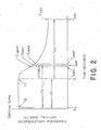
- Fig. 2 shows a graph of a plot of the various phases of the fibrinogen concentration occurring in a typical plasma clotting process. The change in optical density of the plasma level occurs after reagents have been added. The optical density of the plasma sample is monitored, as optically clear fibrinogen converts to turbid fibrin.
- MAP Maximum Acceleration Point A point where the fibrinogen conversion achieves maximum acceleration and begins to decelerate. EOT End of Test Point where there is no appreciable change in the polymerization of fibrin.
- TEOT Theoretical End Of Test The time to convert all fibrinogen based on the time to convert the fibrinogen during the simulated Zero Order Kinetic rate. TX (or T 2 ) Time to Map Time to reach the Maximum Acceleration Point (MAP) from point of injection. MNTX Mean Normal Time to Map The mean of the times of at least 20 normal people to reach then Maximum Acceleration Point (MAP). FTR Fibrinogen Transformation Ratio The amount of fibrinogen converted during a particular time period. This is a percentage of the total Fibrinogen.
- ATF Anticoagulation Therapy Factor The calculated value used to monitor the uses of an anticoagulant without a need for an International Sensitivity Index (ISI) of a thromboplastin.
- ISI International Sensitivity Index
- nATF new Anticoagulation Therapy Factor A replacement for the INR to provide a standardized system for monitoring oral anticoagulant therapy.
- Amso expressed as ATFt and ATFz PR Prothrombin Ratio A value computed by dividing a sample PT by the geometric mean of at least 20 normal people (MNPT).
- INR International Normalized Ratio A parameter which takes into account the various factors involved in anticoagulation therapy monitoring to provide a standardized system for monitoring oral anticoagulant therapy.
- ATFt Anticoagulation Therapy Factor Theoretical Utilizing a calculated Theoretical End Of Test value and the Natural Log “e” to removed the need for an MNPT.
- XR Time to MAP Ratio The value computed by dividing a sample "TX” by the geometric mean of at least 20 normal people "MNTX”.
- INR International Normalized Ratio
- PT patient is the prothrombin time (PT) as an absolute value in seconds for a patient
- PT geometric mean is the mean, a presumed number of normal patients.
- the International Sensitivity Index (ISI) is an equalizing number which a reagent manufacturer of thromboplastin specifies.
- the ISI is a value which is obtained through calibration against a World Health Organization primary reference thromboplastin standard.
- Local ISI (LSI) values have also been used to provide a further refinement of the manufacturer-assigned ISI of the referenced thromboplastin in order to provide local calibration of the ISI value.
- the present invention can be employed for accurate determination of a new Anticoagulant Therapy Factor (nATF) from a human blood sample, for use during the monitoring of oral anticoagulant therapy, without the need for an ISI or LSI value, and without the need for an INR value.
- nATF Anticoagulant Therapy Factor
- blood clotting Factors I, II, V, VII, VIII, IX and X are associated with platelets (Bounameaux, 1957); and, among these, Factors II, VII, IX and X are less firmly attached, since they are readily removed from the platelets by washing (Betterle, Fabris et al, 1977).
- the role of these platelet-involved clotting factors in blood coagulation is not, however, defined.
- the present invention provides a method and apparatus for a new Anticoagulant Therapy Factor (nATF) which may be used for anticoagulant therapy monitoring without the need for INR.
- the International Normalized Ratio is previously discussed in technical articles entitled " PTs, PRs, ISIs and INRs: A Primer on Prothrombin Time Reporting Part I and II respectively," published in November, 1993 and December, 1993 issues of Clinical Hemostasis Review .
- the illustrative example of an analysis which is carried out employing the present invention relies upon the maximum acceleration point (MAP) at which fibrinogen conversion achieves a maximum and from there decelerates, the time to reach the MAP (TX), and the mean normal time to MAP (MNTX), and a fibrinogen transformation rate (FTR), that is, the thrombin activity in which fibrinogen (FBG) is converted to fibrin to cause clotting in blood plasma.
- MAP maximum acceleration point
- TX time to reach the MAP
- MNTX mean normal time to MAP
- FTR fibrinogen transformation rate
- a thromboplastin activates factor VII which, activates factor X, which, in turn, under catalytic action of factor V, activates factor II (sometimes referred to as prothrombin) to cause factor IIa (sometimes referred to as thrombin) that converts fibrinogen (FBG) to fibrin with resultant turbidity activity which is measured, in a manner as to be described hereinafter, when the reaction is undergoing simulated zero-order kinetics.
- the thromboplastin (Tp) does not take part in the reaction where factor IIa (thrombin) converts fibrinogen (FBG) to fibrin which is deterministic of the clotting of the plasma of the patient under consideration.
- the thromboplastin (Tp) only acts to activate factor VII to start the whole cascade rolling.
- differing thromboplastins (Tps) have differing rates of effect on factor VII, so the rates of enzyme factor reactions up to II - IIa (the PT) will vary.
- thromboplastins Tps
- ILR International Normalized Ratio
- ISI International Sensitivity Index
- the thromboplastin (Tp) is needed therefore only to start the reactions that give factor IIa. Once the factor IIa is obtained, fibrinogen (FBG) to fibrin conversion goes on its own independent of the thromboplastin (Tp) used.
- the present method and apparatus has use, for example, in coagulation studies where fibrinogen (FBG) standard solutions and a control solution are employed, wherein the fibrinogen standard solutions act as dormant references to which solutions analyzed with the present invention are compared, whereas the control solution acts as a reagent that is used to control a reaction.
- the fibrinogen standards include both high and low solutions, whereas the control solution is particularly used to control clotting times and fibrinogens of blood samples. It is only necessary to use fibrinogen standards when PT-derived fibrinogens (FBG's) are determined. In connection with other embodiments of the invention, fibrinogen (FBG) standards are not necessary for the INR determination (such as for example INRz described herein).
- Another embodiment provides a method and apparatus for determining an anticoagulation therapy factor which does not require the use of fibrinogen standard solutions.
- the apparatus and method may be carried out without the need to ascertain the mean normal prothrombin time (MNPT) of 20 presumed normal patients.
- MNPT mean normal prothrombin time
- a fibrinogen (FBG) solution of about 10 g/l may be prepared from a cryoprecipitate.
- the cryoprecipitate may be prepared by freezing plasma, letting the plasma thaw in a refrigerator and then, as known in the art, expressing off the plasma so as to leave behind the residue cryoprecipitate.
- the gathered cryoprecipitate should contain a substantial amount of both desired fibrinogen (FBG) and factor VIII (antihemophilic globulin), along with other elements that are not of particular concern to the present invention.
- the 10 g/l fibrinogen (FBG) solution after further treatment, serves as the source for the high fibrinogen (FBG) standard.
- an Owren's Veronal Buffer pH 7.35
- normal saline solution which, after further treatment, may serve as a source of the low fibrinogen (FBG) standard.
- the fibrinogen standard can be created by adding fibrinogen to normal plasma in an empty container.
- the fibrinogen standard is formed from a 1:1 fibrinogen to normal plasma solution.
- 0.5 ml of fibrinogen and 0.5 ml of plasma can be added together in an empty container.
- Thromboplastin calcium is then added to the fibrinogen standard.
- twice the amount by volume of thromboplastin is added into the container per volume amount of fibrinogen standard which is present in the container. The reaction is watched with the apparatus 10.
- FBG fibrinogen
- a chemical method to determine fibrinogen (FBG) is used, such as, the Ware method to clot, collect and wash the fibrin clot and the Ratnoff method to dissolve the clot and measure the fibrinogen (FBG) by its tyrosine content.
- the Ware method is used to obtain the clot and generally involves collecting blood using citrate, oxalate or disodium ethylenediaminetetraacetate as anticoagulant, typically adding 1.0 ml to about 30 ml 0.85% or 0.90% sodium chloride (NaCl) in a flask containing 1 ml M/5 phosphate buffer and 0.5 ml 1% calcium chloride CaCl 2 , and then adding 0.2 ml (100 units) of a thrombin solution.
- the solution is mixed and allowed to stand at room temperature for fifteen minutes, the fibrin forming in less than one minute forming a solid gel if the fibrinogen concentration is normal.
- a glass rod may be introduced into the solution and the clot wound around the rod. See Richard J. Henry, M.D., et al., Clinical Chemistry: Principals and Techniques (2nd Edition) 1974, Harper and Row, pp. 458-459 .
- the Ratnoff method may be utilized to dissolve the clot and measure the fibrinogen (FBG) by its tyrosine content. See " A New Method for the Determination of Fibrinogen in Small Samples of Plasma", Oscar D. Ratnoff, M.D. et al., J. Lab. Clin. Med., 1951: V.37 pp. 316-320 .
- the Ratnoff method relies on the optical density of the developed color being proportional to the concentration of fibrinogen or tyrosine and sets forth a calibration curve for determining the relationship between optical density and concentration of fibrinogen.
- the addition of a fibrinogen standard preferably is added to the plasma sample based on the volume of the plasma.
- the addition of the reagent Thromboplastin C serves as a coagulant to cause clotting to occur within a sample of citrated blood under test which may be contained in a container 8.
- the A/D converter 26 of Fig. 1 will count and produce a digital value of voltage at a predetermined period, such as once every 0.05 or 0.01 seconds.
- these voltage values are stored and then printed by the recorder as an array of numbers, the printing being from left to right and line by line, top to bottom. There are typically one hundred numbers in the five groups representing voltage values every second and hence, one line represents one-fifth of a second in time (20x0.01 seconds).
- Fig. 2 illustrates the data point locations of a clotting curve related to a coagulation study which illustrates the activation and conversion of fibrinogen to fibrin.
- Fig. 2 illustrates a "clot slope" method that may be used in a blood coagulation study carried out for determining a new anticoagulant therapy factor (nATFa).
- nATFa new anticoagulant therapy factor
- a quantity c MAP and a corresponding time t MAP define a maximum acceleration point (MAP). Fibrin formation, after a short lag phase before the MAP, occurs for a period of time, in a linear manner. Fibrinogen (FBG) is in excess during this lag phase, and fibrin formation appears linear up to the MAP.
- FBG Fibrinogen
- the deceleration of fibrinogen (FBG) to fibrin conversion continues until a quantity c EOT is reached at a time t EOT .
- the time t EOT is the point where the deceleration of the fibrinogen (FBG) to fibrin conversion corresponds to a value which is less than the required amount of fibrinogen (FBG) that was present in order to start the fibrinogen (FBG) to fibrin conversion process.
- the time t EOT represents the ending point of the fibrinogen (FBG) to fibrin conversion in accordance with the coagulation study exemplified herein, which may be referred to as the end of the test (EOT).
- the fibrinogen (FBG) to fibrin conversion has a starting point of t 1 and an ending point of t EOT .
- the differential of these times, t 1 and t EOT define a second delta (IUT).
- the fibrinogen (FBG) to fibrin conversion is defined, in part, by the point (t EOT ) where the deceleration of conversion becomes less than the instrument value of about 0.05 g/l that is used to detect the clot point (t 1 ).
- t EOT the point where the deceleration of conversion becomes less than the instrument value of about 0.05 g/l that is used to detect the clot point (t 1 ).
- Adhering to the four given critical parameters is an example of how the present apparatus and method may be used to carry out a coagulation study to determine a specific quantity of fibrinogen. In order for that specific amount of fibrinogen to be determined, it is first necessary to detect a clot point (t 1 ).
- nATFz XR 2 - nFTR
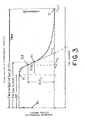
- This embodiment includes all features as laid down in claim 1 and utilizes a zero order line (L) to obtain a first delta, IUXz, which is a first differential taken along the simulated zero order kinetic line (L), and along the segment between the start of the simulated zero order kinetic (T 2 S) to the last highest absorbance value (T 2 ) (i.e., the last highest absorbance value of a simulated zero order kinetic).
- a zero order line L
- IUXz is a first differential taken along the simulated zero order kinetic line (L)
- T 2 S the last highest absorbance value
- T 2 the last highest absorbance value of a simulated zero order kinetic
- the values for "T” correspond with times, and the values for "c” correspond with quantity, which is measured in instrument units based on optical density readings (also referred to as optical density or o.d.).
- the time T 2 is the point of maximum acceleration of the fibrinogen (FBG) to fibrin conversion and is also the point where deceleration of fibrinogen (FBG) to fibrin conversion begins.
- IUXz is the change in optical density from the beginning of the at the time T 2 S at which the simulated zero order kinetic begins to the optical density at time T 2 which is the maximum acceleration point or the last highest delta absorbance value of a simulated zero order kinetic.
- the second delta in particular (IUTz) is the change in optical density at the time T 2 S to the optical density measured at time T 3 , where time T 3 is the end of the test (EOT).
- the (IUXz) represents the fibrinogen (FBG) converted between time T 2 S and T 2 .
- the (IUTz) represents fibrinogen converted from the time T 2 S to the end of the test or T 3 .
- the maximum acceleration ratio (XR) for this embodiment is calculated to arrive at the new alternate anticoagulation therapy factor (nATFz).
- the maximum acceleration ratio (XR) is defined as the time to maximum acceleration from reagent injection (TX) divided by the mean normal TX value of a number of presumed normal specimens (MNTX).
- TX time to maximum acceleration from reagent injection
- MNTX mean normal TX value of a number of presumed normal specimens
- the clotting curve of Fig. 3 illustrates the values ascertained in arriving at the new alternate anticoagulation therapy factor (nATFz).
- the preferred IBM-compatible computer 30 of Fig. 1 stores and manipulates these digital values corresponding to related data of Fig. 3 and is preferably programmed as follows:
- the new anticoagulation therapy factor (nATFz) does not require an ISI value, as was previously used to determine anticoagulation therapy factors.
- the new anticoagulation therapy factor (nATFz) uses for its ascertainment the values extracted from the clotting curve (see Fig. 3 ), in particular (nFTRz) (determined based on IUXz and IUTz), and (TX). In carrying out coagulation studies, the new anticoagulant therapy factor (nATFz) may replace INR in anticoagulant therapy management.
- the apparatus and method for obtaining a new anticoagulant therapy factor, (nATFz), may be accomplished without encountering the complications involved with obtaining the prior art quantities International Normalized Ratio (INR) and International Sensitivity Index (ISI).
- INR International Normalized Ratio
- ISI International Sensitivity Index
- the new anticoagulant therapy factor preferably is a replacement for the International Normalized Ratio (INR), hence it may be referred to as INRz.
- INRz International Normalized Ratio
- Existing medical literature, instrumentation, and methodologies are closely linked to the International Normalized Ratio (INR).
- the nATFz was compared for correlation with the INR by comparative testing, to INR quantities, even with the understanding that the INR determination may have an error of about ten (10) % which needs to be taken into account to explain certain inconsistencies.
- Table 2 below, includes anticoagulant therapy factors obtained from patients at two different hospitals.
- the ATFz values were obtained, with GATFz representing one geographic location where patients were located and MATFz being another location.
- the ATFz was obtained as the new anticoagulant therapy factor, and as illustrated in Tables 4 and 5, below, compares favorably to results obtained for INR determinations.
- ATFt new anticoagulant therapy factor
- the embodiment includes all features as laid down in claim 8.
- the alternate embodiment for determining ATFt eliminates the need for determining a mean normal prothrombin time (MNPT) (or MNXT) and ISI, saving considerable time and costs, and removing potential sources of error, as the MNPT (the expected value of MNPT's depending on the varying 20 presumed normals population) and ISI (generally provided by the manufacturer of the reagent - such as, for example, the thromboplastin, etc.) are not required for the determination of the ATFt.
- MNPT mean normal prothrombin time
- ISI generally provided by the manufacturer of the reagent - such as, for example, the thromboplastin, etc.
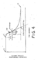
- An alternate embodiment for determining ATFt is illustrated in accordance with the clotting curve shown in
- Fig. 4 The clotting curve of Fig. 4 illustrates values ascertained in arriving at the alternate new anticoagulation therapy factor (nATFt).
- the alternate embodiment utilizes the zero order line (L) to obtain a first delta, IUXz, which is a first differential taken along the simulated zero order kinetic line (L), and along the segment between the start of the simulated zero order kinetic (T 2 S) to the last highest absorbance value (T 2 ) (i.e., the last highest absorbance value of a simulated zero order kinetic).
- a first delta, IUXz is a first differential taken along the simulated zero order kinetic line (L), and along the segment between the start of the simulated zero order kinetic (T 2 S) to the last highest absorbance value (T 2 ) (i.e., the last highest absorbance value of a simulated zero order kinetic).
- T 1 time
- T 2 maximum acceleration point
- the time T 2 is the point of maximum acceleration of the fibrinogen (FBG) to fibrin conversion and also is the point where deceleration of fibrinogen (FBG) to fibrin conversion begins.
- IUXz represents a change in optical density (o.d.) from the beginning of the at the time T 2 S at which the simulated zero order kinetic begins to the optical density at time T 2 which is the maximum acceleration point or the last highest delta absorbance value of a simulated zero order kinetic.
- the value IUXz is generally expressed in instrument units (corresponding to absorbance or percent transmittance) and may generally be referred to as optical density or o.d. Fig.
- the second delta in particular (IUTz) represents a change in optical density at a time T 2 S to the optical density measured at a time T 3 , where time T 3 is the end of the test (EOT).
- the (IUXz) represents the fibrinogen (FBG) converted between time T 2 S and T 2 .
- the (IUTz) represents fibrinogen converted from the time T 2 S to the end of the test or T 3 .
- the value TEOT is the elapsed time to convert the total instrument units (TIU) at the zero order kinetic rate, which is representative of the fibrinogen in the sample undergoing the conversion to fibrin.
- a second value, V2, also referred to as a multiplier, is determined based on the value T 2 S.
- the second value, V2 is obtained by taking the value of the time (T 2 S) corresponding to a second time (t2) or the maximum acceleration point (Tmap), and scaling this value.
- the multiplier is derived from the natural log base "e", which is 2.71828, scaled to provide an appropriately decimaled value.
- the scaling number used in the example set forth for this embodiment is 100.
- the invention also discloses an alternate embodiment of an anticoagulant therapy factor, ATFt2, which does not require the ascertainment of a mean normal prothrombin time (MNPT) or use of an ISI value.
- ATFt2 an anticoagulant therapy factor
- the alternate embodiment is derived using the expression (5), wherein the IUTz is replaced by the expression (IUTz+ IULz).
- the method is carried out to ascertain the values for Value1 and Value2, in the manner described herein, with Value 1 being obtained through expression (5.1):
- IULz is time to convert the lag phase fibrinogen (FBG) measured along the ordinate between T1 and T2S.
- TEOT theoretical end of test
- FBG fibrinogen
- Fig. 5 illustrates the fibrinogen lag phase and the TEOT obtained from the line L2, and shows the IULz.
- the apparatus comprises a computer which is programmed to record, store and process data.
- the zero order rate is determined by ascertaining data from analyzing the sample, and optical density properties.
- One example of how this may be accomplished is using two arrays, a data array and a sub array.
- a data array may be ascertained by collecting data over a time interval.
- the data array may comprise a sequential list of optical densities, taken of a sample by an optical analytical instrument, such as, for example, a spectrophotometer, for a frequency of time.
- the frequency of sample data is taken every 100 th of a second.
- a computer is programmed to record the optical density of the sample, every 100 th of a second.
- NOW and THEN Two values, NOW and THEN, for the data array are provided for ascertaining the Prothrombin Time (PT) (which is the time point T 1 ), maximum acceleration point (MAP), and end of test point (EOT).
- PT Prothrombin Time
- MAP maximum acceleration point
- EOT end of test point
- Two time definitions may be specified, one being the interval between NOW and THEN on the clotting curve, which may be 2.72 seconds (272/100 th of a second), the second being the size of the filter used for signal averaging.
- NOW is the sum of the last 20 optical densities and THEN is the sum of the 10 prior data points 2.72 seconds prior to NOW.
- a graphical illustration is provided in Fig. 5 . As illustrated in Fig. 5 , four values are defined: SUM(NOW), SUM(THEN), AVERAGE(NOW) and AVERAGE(THEN). The average is the sum divided by the filter value.
- the sub array may be defined as a sequential list of delta absorbance units. This may begin at T 1 , the prothrombin time (PT), and continue until the last highest delta absorbance (delta A) has been detected, then continues an additional five (5) seconds to insure the last delta A has been found.
- T 2 S may be accomplished by locating within the sub array, the first occurrence of when the sub array delta value is greater than or equal to 80% of the highest delta absorbance units.
- the first derivative is ascertained by computing the difference between (NOW) and (THEN).
- the PT is ascertained by determining the point prior to the positive difference between AVERAGE(THEN) and AVERAGE(NOW) for a period of 2.72 seconds or 272 ticks.
- the MAP is the point where the last highest difference between SUM(THEN) and SUM(NOW) has occurred.
- the computer may be programmed to store this delta A value in the sub array.
- the EOT may be ascertained by determining the point prior to where the difference between SUM(THEN) and SUM(NOW) is less than one.
- Table 2 illustrates examples of samples, identified by ID numbers, along with corresponding data which compares the ATF values obtained for an ATF determined through the prior method, using ISI and INR values (represented as ATFa), an ATF determined through the use of a zero order kinetic reaction using the MNTX (nATFz), and an ATF determined without using the MNXT or ISI (nATFt).
- the data in table 2 represents universal laboratory data from combined locations for the patients listed. The data is based on analysis of absorbance data, storage of the data by the computer, such as, for example, with a storage device, like a hard drive, and retrieving the data and processing the data.
- the data, in the example represented in Table 2 was processed using the definitions and NOW and THEN intervals.
- AINR in Table 2 represents the INR value obtained pursuant to the World Health Organization (WHO), using expressions (A) and (B) above.
- GINR and MINR correspond to INR values used to determine the comparison data set forth in Tables 4 and 5.
- the determination of the new anticoagulant therapy factor may be carried out with a computer.
- the gathering, storing, and manipulation of the data generally illustrated in Fig. 4 may be accomplished by computer 30 of Fig. 1 that receives digital voltage values converted, by the A/D converter 26, from analog voltage quantities of the photocell 10 detection means.
- the IBM-compatible computer 30 of Fig. 1 stores and manipulates these digital values corresponding to related data of Fig. 4 and may be programmed as follows:
- the new fibrinogen transformation rate has an upwardly rising (increasing quantities) slope prior to the maximum acceleration point (MAP) and, conversely, has a downwardly falling (decreasing quantities) slope after the maximum acceleration point (MAP).
- the computer 30 is programmed to ascertain the value for the time to start (T 2 S) which corresponds with the time at which the simulated zero order kinetic rate begins.
- the computer 30 may be used to manipulate and derive the quantities of expression (4) to determine a new anticoagulant therapy factor nATFt utilizing known programming routines and techniques.
- the data collected by a computer 30 may be used to manipulate and derive the new anticoagulant therapy factor (nATFt) of expression (4).
- nATFt new anticoagulant therapy factor
- using known mathematical techniques may derive the theoretical end of test TEOT of expression (5) and the second value VALUE 2 of expression (7) which, in turn, are used to determine the new anticoagulant therapy (nATFt) of expression (4).
- the determination is based on the patient's own sample, and does not rely on the determination of normal prothrombin times for the reagent used (e.g., thromboplastin, innovin or the like). With the nATFt, no longer does the accuracy of the quantities determined depend, in whole or part, on the number of specimens used, that is, the number of stable (or presumed stable) patients.
- the reagent used e.g., thromboplastin, innovin or the like.
- the new anticoagulation therapy factor (nATFt) does not require an ISI value, as was previously used to determine anticoagulation therapy factors.
- the new anticoagulation therapy factor (nATFt) uses for its ascertainment the values extracted from the clotting curve (see Fig. 4 ), in particular T 2 S, Tmap, TEOT, c T2S , cmap and ceot.
- the ISI is not required, nor is the MNPT, or the need to obtain and calculate the prothrombin times (PT's) for 20 presumed normal patients.
- the new anticoagulant therapy factor (nATFt) may replace INR in anticoagulant therapy management.
- the computer 30 has knowledge of the values obtained for the fibrinogen reaction, to ascertain the (nATFt).
- the present invention provides an apparatus and method for obtaining a new anticoagulant therapy factor (nATF) without encountering the complications involved with obtaining the prior art quantities International Normalized Ratio (INR) and International Sensitivity Index (ISI).
- INR International Normalized Ratio
- ISI International Sensitivity Index
- the new anticoagulant therapy factor preferably is a replacement for the International Normalized Ratio (INR).
- INR International Normalized Ratio
- Existing medical literature, instrumentation, and methodologies are closely linked to the International Normalized Ratio (INR).
- the nATFt was compared for correlation with the INR by comparative testing, to INR quantities, even with the understanding that the INR determination may have an error of about +/- 15%, at a 95% confidence interval, which needs to be taken into account to explain certain inconsistencies.
- nATFt new anticoagulant therapy factor
- Table 3 (Part A) and Table 3 (Part B) provide corresponding data for a coagulation study.
- Table 3 (Part A and B) the following references are used: Column Label Definition A ID Sample ID B OD@T 2 S OD at the start of Zero Order Kinetic C OD@Map OD at the Maximum Acceleration Point (MAP) D OD@Eot OD at the END OF TEST (Eot) E ⁇ T 2 SMap Delta of Column B and C creating the IUXz F ⁇ T 2 SEot Delta of Column B and D creating the IUTz G FTR od Ratio of Column E divided by F The FTR od is subtracted from 2 creating the Exponent that replaces the ISI H Time@T 2 S Time at the start of Zero Order Kinetics I Time@Map Time at the Maximum Acceleration Point (MAP) J Time@TEot Time at the Theoretical End of Test (TEOT) K ⁇ T 2 SMap Delta of Column H and I creating the IUXz (and ZTM) L
- Results between patients in two different geographic locations were compared for correlation with each other.
- This comparison is expressed in Table 4 below, and includes a comparison of INR values calculated by the WHO method for each respective location, with GInr representing one location for these traditionally WHO determined values, and MInr representing values based on data obtained at the other location.
- the values identified as ATFz and ATFt such as, GATFt and MATFt, and GATFz and MATFz, represent anticoagulant therapy factors derived from the expressions (1) through (9) above.
- the ATFa represents an anticoagulation therapy factor derived from our method and apparatus for the expression
- ATFa XR (2-nFTR) wherein a maximum acceleration point is obtained
- nFTR IUX/IUT
- IUX is the change in optical density from a time prior to the MAP time (t ⁇ MAP which is t MAP minus some time from MAP) to the optical density at a time after the MAP time (t> MAP which is t MAP plus some time from MAP)
- IUT the change in optical density at the time t 1 to the optical density measured at time T EOT , where time T EOT is the end of the test (EOT).
- the (IUX) represents the fibrinogen (FBG) for MAP (-a number of seconds) to MAP (+a number of seconds) (that is the fibrinogen (FBG) converted from t ⁇ MAP to t> MAP on Fig. 2 )
- the (IUT) represents fibrinogen converted from c 1 to c EOT (that is the fibrinogen converted from t 1 to T EOT , see Fig. 2 ).
- Table 7 represents a comparison of the data from Table 6. TABLE 7 "r” “m” “b” StdErr StdDev INR vs INRz 0.988 0.988 0.059 0.190 1.201 ATFt 0.984 0.966 0.568 0.215 1.238 ATFt2 0.983 0.913 0.504 0.219 1.257 ATFt - vs ATFt2 1.000 0.946 0.068 0.022 1.264
- Table 8 provides comparative data for the anticoagulant therapy factors, similar to Table 2, but using the ATFt2 method from expressions (4) and (5.1) for corresponding GINRt2 and MINRt2 values.
- ID AINR GINR GINRa GINRz GINRt2 MINR MINRa MINRz MINRt2 U0800 2.0 2.0 2.0 1.7 2.1 2.1 2.2 2.1 U7440 2.6 3.0 3.0 2.9 2.9 3.0 3.0 2.8 3.4 U7443 2.0 2.0 2.0 2.0 1.8 2.1 2.2 2.1 1.8 U7458 1.4 1.4 1.4 1.2 1.4 1.3 1.3 U7465 9.7 7.4 8.1 6.6 7.9 7.1 7.5 8.1 7.8 U7469 1.1 1.1 1.1 1.1 0.9 1.2 1.1 1.0 U7470 3.2 3.4 3.6 3.4 3.2 3.6 3.7 3.8 3.8 U8080 3.1 3.6 3.6 3.3 3.6 3.3 3.3 3.5 3.4 U8087 1.9 1.9 1.9 1.9 1.9 1.9 1.9
- Table 9 provides comparative data for the ATFa, ATFz and ATFt2 and INR values calculated by the WHO method for each respective location, with GInr representing one location for these traditionally WHO determined values, and MInr representing values based on data obtained at the other location.
- the values identified as ATFz and ATFt2, such as, GATFt2 and MATFt2, and GATFz and MATFz, represent anticoagulant therapy factors derived from the expressions (1) through (9) above, inclusive of expressions (5.1) and (8.1).
- the new anticoagulation therapy factor (ATFt2) was compared with the WHO method for determining ATF.
- the WHO method utilizes the mean prothrombin time of 20 presumed normal patients.
- MNPT is, of course, less problematic for INRs than the exponent, ISI. Comparative results, showing interlab results, are provided in Table 11. ATFt is seen to be numerically equal to WHO/INRs determined in both analytical instruments, namely, the MDA-Electra 9000C and the POTENS+.
- Table 11 provides statistical comparisons for results obtained using two POTENS+ coagulometers (one designated as GINR and another designated as MINR), and using a Bio Merieux MDA-180 coagulometer (designated as AINR).
- the POTENS+, WHO/INRs, INR z s, and ATFts and the MDA-180 (AINR) WHO/INRs are compared.
- Statistical data and Bland-Altman plot data demonstrate that the new anticoagulant therapy factor ATFt may replace WHO/INR and provide results which are within the parameters of traditional therapeutic or reference ranges.
- an article is provided to derive an anticoagulant therapy factor (ATF).
- the article comprises stored instructions on a storage media which is read and processed with a processor.
- the computer is provided with a stored set of instructions, or chip, which is programmed to determine a new ATF for the spectral data obtained from the coagulation activity of a sample.
- the computer chip is preprogrammed with a set of instructions for cooperating with the output of a photodetection device, such as, the device shown and described in Fig. 1 , which provides electrical data to said computer processor and/or storage device as a function of the optical density for a sample being analyzed.
- the chip is employed in, or used with, an apparatus having input means and storage means for storing data.
- the set of instructions on the chip includes instructions for carrying out the steps of determining one or more anticoagulant therapy factors based on the expressions (1) through (9), inclusive of expressions (5.1) and (8.1).
Landscapes
- Health & Medical Sciences (AREA)
- Life Sciences & Earth Sciences (AREA)
- Chemical & Material Sciences (AREA)
- Engineering & Computer Science (AREA)
- Physics & Mathematics (AREA)
- Hematology (AREA)
- Immunology (AREA)
- General Physics & Mathematics (AREA)
- Molecular Biology (AREA)
- General Health & Medical Sciences (AREA)
- Analytical Chemistry (AREA)
- Biochemistry (AREA)
- Pathology (AREA)
- Urology & Nephrology (AREA)
- Biomedical Technology (AREA)
- Plasma & Fusion (AREA)
- Cell Biology (AREA)
- Microbiology (AREA)
- Biotechnology (AREA)
- Chemical Kinetics & Catalysis (AREA)
- Food Science & Technology (AREA)
- Medicinal Chemistry (AREA)
- Investigating Or Analysing Biological Materials (AREA)
Claims (16)
- Ein Verfahren zur Bestimmung eines neuen Antikoagulanstheraple-Faktors (nATFz), welcher sich bei der Überwachung von Antikoagulanstherapie in Körperflüssigkeiten von Patienten als nützlich erwiesen hat, das die folgenden Schritte umfasst:a. Entwicklung einer Reihe von analogen elektrischen Spannungssignalen, wobei die Voltamplituden proportional zur einer optischen Dichte in einer Fibrinogen enthaltenden Flüssigkeitsprobe sind;b. Umwandeln der entwickelten analogen elektrischen Spannungssignale in eine Reihe von digitalen Spannungssignalen;c. Zugabe eines Koagulans in die Flüssigkeitsprobe, wodurch eine plötzliche Änderung in der optischen Dichte der Flüssigkeitsprobe verursacht wird, und die plötzliche Änderung eine plötzliche Änderung des Werts der Amplitude der elektrischen Analogsignale bewirkt, wodurch wiederum eine plötzliche Änderung im Wert der digitalen Spännungssignale erzielt wird, wobei der Wert der digitalen Spannungssignale ein direkter Hinweis auf die Fibrinogen-Konzentration in der Flüssigkeitsprobe ist;d. Aufzeichnung eines Zeitpunkts T0 der plötzlichen Änderung im Wert des digitalen Spannungssignals;e. Überwachung der digitalen Spannungssignalwerte in Bezug auf Koagulansaktivität;f. Aufzeichnung eines Zeitpunkts T1 welcher dem Beginn der Gerinnselbildung entspricht;g. Überwachung der digitalen Spannungssignalwerte für weitere Fibrinogen-Konzentration Quantitäten;h. Aufzeichnung eines Zeitpunkts T2S welcher dem Ausgangspunkt einer simulierten Kinetik nullter Ordnung entspricht und Aufzeichnung des Werts des digitalen Spannungssignals einer Fibrinogen-Konzentration CT2S;i. Aufzeichnung eines Zeitpunkts T2 sowie des digitalen Spannungssignalwerts einer vorgegebenen Fibrinogen-Konzentration Quantität CT2, wobei T2 dem Punkt bei dem die maximale Beschleunigung des Umwandelns von Fibrinogen zu Fibrin stattfindet, entspricht.j. Aufzeichnung einer Ablaufzeit zwischen T0 and T2, welche ein Zeitmaß zur maximalen Beschleunigung der Umwandlung von Fibrinogen zu Fibrin (TX) ab der Koagulans-Injektion in Stufe (c) festlegt;k. Überwachung in Bezug auf eine Differenzändemng der digitalen Spannungssignalwerte welche die vorgegebene Fibrinogen-Konzentration Quantität CT2 beinhalten; wobei die Fibrinogen-Konzentration Quantität CT2 sowie die Zeit T2 einen maximalen Beschleunigungspunkt (MAP) und ein Zeitmaß zur maximalen Beschleunigung der Umwandlung von Fibrinogen zu Fibrin ab der Koagulans-Injektion (TX) festlegen, wobei TX als die Ablaufzeit vom Zeitpunkt der Koagulans-Injektion T0 bis zum Zeitpunkt der maximalen Beschleunigung T2 gemessen wird;I. Überwachung der digitalen Spannungssignalwerte T25 und T2 für die jeweiligen vorgegebenen Fibrinogen-Konzentration Quantitäten CT2S und CT2 wobei die Differenz zwischen den CT2S und CT2 Quantitäten eine erste Differenz IUXz ist;m. Überwachung der digitalen Spannungssignalwerte zu einem Zeitpunkt der im Wesentlichen der vollständigen Umwandlung von Fibrinogen zu Fibrin T3 entspricht und Aufzeichnung des Werts des digitalen Spannungssignals der vorgegebenen Fibrinogen-Konzentrationsquantität CT3 zu einem Zeitpunkt T3, wobei die Differenz zwischen den Quantitäten CT2 und CT3 eine zweite Differenz IUTz ist, wobei die erste Differenz IUXz durch die zweite Differenz IUTz geteilt wird um einen prozentualen Anteil des gesamten geänderten digitalen Spannungssignalwerts festzulegen, der durch einen Gesamtbereich welcher die neue Fibrinogen Umwandlungsgeschwindigkeit (nFTR) definien ist, wobei nFTR = IUXz/IUTz; wobei ein maximales Beschleunigungsverhältnis (XR) durch die Zeit bis zur maximalen Beschleunigung der Umwandlung von Fibrinogen zu Fibrin ab der Koagulans-Injektion (TX) geteilt durch einen durchschnittlichen normalen TX-Wert (MNTX) aus einem Muster von Patienten mit vermutlicher normaler Koagulation bestimmt wird; wobei der neue Antikoagulanstherapie Faktor (nATFz) durch die folgende Beziehung ausgedrückt wird:

- Das Verfahren gemäß Anspruch 1, wobei die Probe von Patienten mit vermutlicher normaler Koagulation entweder 20 Patienten oder mehr als 20 Patienten ist.
- Das Verfahren gemäß Anspruch 1, wobei MNTX der Durchschnittswert der TX einer Vielzahl von Proben von mindestens zwanzig (20) Patienten mit vermutlicher normaler Koagulation ist.
- Das Verfahren gemäß irgend einem der vorangehenden Ansprüche, wobei die Werte T2S and T2 Punkte entlang einer simulierten kinetischen Linie nullter Ordnung (L) darstellen, wobei T2S einem annähernden Zeitpunkt des Beginns einer simulierten Kinetik nullter Ordnung entspricht, und wobei T2 dem letzt höchsten Delta-Absorptionswert einer simulierten Kinetik nullter Ordnung entspricht.
- Das Verfahren gemäß irgend einem der vorangehenden Ansprüche, wobei die Flüssigkeitsprobe Blutplasma ist.
- Das Verfahren gemäß irgend einem der vorangehenden Ansprüche, wobei das in die Probe injizierte Koagulans Thromboplastin mit Calciumion Ist.
- Das Verfahren gemäß irgend einem der vorangehenden Ansprüche, wobei das analoge elektrische Spannungssignal durch die Durchstrahlung eines Lichtbündels durch eine Plasmaprobe entwickelt wird und die gemessenen Variationen des Lichtdurchgangs erfasst werden um entsprechende Variationen in dem erzeugten elektrischen Signal weiterzubilden.
- Ein Verfahren zur Bestimmung eines neuen Antikoagulans-Therapiefaktors (nATF), das bei der Überwachung von Antikoagulans-Therapie in Körperflüssigkeiten von Patienten nützlich ist, das die folgenden Schritte umfasst:a. Bestimmung der Startzeit, dargestellt durch (T2S) einer nullten Ordnung kinetischer Umwandlungsgeschwindigkeit von Fibrinogen zu Fibrin für eine Reaktion einer Reagens welches mit dem anwesenden Fibrinogen in der Körperflüssigkeitsprobe reagiert, um Fibrinogen in Fibrin umzuwandeln, sowie eines Wertes der Probe, welcher in Messinstrumenteinheiten basiert auf Ablesung der optischen Dichte gemessen wird, und mit der Startzeit (T2S) übereinstimmt;b. Bestimmung der Zeit bis zur maximalen Beschleunigung (Tmap) für die Umwandlungsgeschwindigkeit von Fibrinogen zu Fibrin für die Körperflüssigkeitsprobe;c. Bestimmung einer ersten Differenz (IUX) die in Messinstrumenteinheiten dargestellt und mit den Absorptionswerten die zwischen dem Start (T2S) der kinetischen Rate nullter Ordnung und der Zeit bis zur maximalen Beschleunigung (Tmap) übereinstimmt;d. Bestimmung einer zweiten Differenz (IUT), die auf der Änderung in der erzielten optischen Dichte zwischen einem theoretischen Ende des Tests (TEOT) für die kinetische Rate beruht, die im Wesentlichen der vollständigen Umwandlung von Fibrinogen zu Fibrin entspricht, und dem Start (T2S);e. Bestimmung eines ersten Werts V1 der auf dem Verhältnis von IUT und IUX basiert;f. Bestimmung eines Werts V2 der auf einem Bruchteil der Startzeit (T2S) basiert, undg. Bestimmung eines neuen Antikoagulans-Therapiefaktorwerts (nATF) durch Einbeziehung des Produkts von V1 und V2.
- Das Verfahren gemäß Anspruch 8, wobei der Wert V1 das theoretische Ende des Tests (TEOT) ist und durch den Wert des IUT/IUX Verhältnisses maßstabsgerecht mit einem Multiplikatorzeitwert (ZTM) bestimmt wird, wobei der Wert TEOT durch den Ausdruck TEOT = ZTM/IUX*IUT erhalten wird.
- Das Verfahren gemäß Ansprüchen 8 oder 9, wobei der Start der Gerinnselbildung durch die Zeit T1 dargestellt ist, und wobei der Wert V1 das theoretische Ende des Tests (TEOT) ist und durch den Wert des IUT/IUX Verhältnisses maßstabsgerecht mit einem Multiplikatorzeitwert (ZTM) bestimmt wird, welches die Zeit zwischen Tmap und T2S ist, wobei der Wert TEOT durch den Ausdruck TEOT = ZTM/IUX*(IUT+IUL) erhalten wird, wobei IUL die Einheit des Absorptionswerts der Probe der zwischen Zeit T1 und Zeit T2S gemessen wird, darstellt.
- Das Verfahren gemäß irgend einem der Ansprüche 8-10, wobei der Bruchteil der Startzeit (T2S) eine Bruchzahl ist, die auf dem Logarithmus e beruht, wobei e = 2,71828
- Das Verfahren gemäß Anspruch 11, wobei der auf dem Logarithmus (e) basierte Bruchteil maßstäblich ist, um einen Bereich von einstelligen Stellenwerten vorzusehen.
- Das Verfahren gemäß irgend einem der Ansprüche 8-12, wobei der Wert V2 durch eine Bruchzahl der Startzeit gemäß der Formel T2S durch das hundertfache Produkt des Logarithmus e geteilt bestimmt wird, bzw. T2S/(100*Logarithmus e), wobei e = 2,71828.
- Eine Vorrichtung zur Bestimmung eines Antikoagulans-Therapiefaktors (nATF) welcher zur Überwachung der Antikoagulans-Therapie in Körperflüssigkeiten von Patienten nützlich ist, wobei die Vorrichtung einen Prozessor sowie einen vorprogrammierten Computerchip mit einem Satz von Anweisungen für die Kooperation mit der Ausgabe eines Photodetektors, welcher elektrische Daten als eine Funktion optischer Dichte für eine analysierte Probe für den Prozessor vorsieht, hat, wobei die Vorrichtung Eingabemittel und Speichermittel zur Datenspeicherung aufweist, wo sich unter dem Satz von Anweisungen ebenfalls Anweisungen zur Bestimmung eines oder mehrerer Antikoagulans-Therapiefaktoren auf Grundlage der aufgezeigten Stufen in irgend einem der Ansprüche 1-7 oder 8-13 befinden.
- Die Vorrichtung gemäß Anspruch 14, wobei die Vorrichtung ein analoges elektrisches Spannungssignal durch die Durchstrahlung eines Lichtbündels durch eine Plasmaprobe erzeugt und die Variationen des Lichtdurchgangs erfasst um entsprechende Variationen in dem erzeugten elektrischen Signal weiterzubilden.
- Eine Vorrichtung zur Bestimmung eines neuen Antikoagulans-Therapiefaktors (nATF) gemäß Anspruch 14, der nützlich in der Überwachung von Antikoagulans-Therapie in Körperflüssigkeiten von Patienten ist, wobei die Vorrichtung zur Ausführung folgender Stufen angepasst ist:a. Entwicklung eines analogen elektrischen Spannungssignal mit einer Amplitude die proportional zur optischen Dichte einer Fibrinogen enthaltenden Flüssigkeitsprobe ist, wobei die Stufe durch Mittel einschließlich einer Lichtquelle, eines Reagenzglases, einer Fotozelle, einer Batterie und eines Regelwiderstandes, ausgeführt wird;b. Umwandlung und Aufzeichnung des entwickelten analogen Signals In einer Relhe digitaler Spannungssignalwerte, wobei die Stufe durch Mittel einschließlich eines Analog-Digital-Umwandlers und eines Computers durch die Zusammenarbeit beider ausgeführt wird,c. Zugabe eines Koagulans in die Flüssigkeitsprobe, wodurch eine plötzliche Änderung in der optischen Dichte der Flüssigkeitsprobe erzeugt wird und die plötzliche Änderung eine plötzliche Änderung in der Amplitude der elektrischen Analogsignale bewirkt, wodurch wiederum eine plötzliche Änderung im Wert der digitalen Spannungssignale erzeugt wird, wobei der Wert der digitalen Spannungssignale einen direkten Hinweis auf die Fibrinogen Konzentration in der Flüssigkeitsprobe darstellt;d. Überwachung der digitalen Spannungssignalwerte in Bezug auf Koagulansaktivität, wobei die Stufe durch Mittel einschließlich eines Computers ausgeführt wird,e. Aufzeichnung eines Zeitpunkts (T2S) welcher dem Beginns einer kinetischen Rate nullter Ordnung der Umwandlung von Fibrinogen zu Fibrin für eine Reaktion eines Reagens entspricht, welches mit anwesendem Fibrinogen in der Körperflüssigkeitsprobe reagiert um Fibrinogen zu Fibrin umzuwandeln, sowie eines Wertes der Probe, welcher in Messinstrumenteinheiten basiert auf Ablesung der optischen Dichte gemessen wird, und mit der Startzeit (T2S) übereinstimmt;f. Aufzeichnung derZeit bis zur maximalen Beschleunigung (Tmap) für die Umwandlungsrate von Fibrinogen zu Fibrin für die Körperflüssigkeitsprobe;g. Überwachung der digitalen Spannungssignalwerte zu den Zeitpunkten T2S sowie die Zeit zur maximalen Beschleunigung (Tmap) für die jeweilig vorgegebenen Fibrinogen-Konzentrationsquantitäten CT2s und CTmap und für die Berechnung der Differenz zwischen den Quantitäten CT2s und CTmap zur Bereitstellung eines ersten Differenzials (IUXt), wobei die Stufe durch Mittel einschließlich des Computers ausgeführt wird,h. Überwachung der digitalen Spannungssignalwerte zu den Zeitpunkten T2S und eines theoretischen Ende des Tests TEOT für die jeweilig vorgegebenen Fibrinogen-Konzentrationswerte GT2s und CTEOT und für die Berechnung der Differenz zwischen den Quantitäten CT2s und CTEOT zur Bereitstellung einer zweiten Differenz (IUTt), wobei das theoretische Ende des Tests TEOT für die Kinetik nullter Ordnung der Wesentlichen vollständigen Umwandlung von Fibrinogen zu Fibrin entspricht, wobei die Stufe durch Mittel einschließlich des Computers ausgeführt wird,i. Bestimmung eines ersten Werts V1 der auf einem Verhältnis von IUTt und IUXt basiert; wobei die Stufe durch Mittel elnschließlich des Computers ausgeführt wird,j. Bestimmung eines Werts V2 auf der Grundlage eines Bruchteils der Startzeit (T2S); wobei die Stufe durch Mittel einschließlich des Computers ausgeführt wird, undk. Übernahme des Produkts von V1 und V2, wobei das Produkt davon der neue Antikoagulans-Therapiefaktor (nATF) ist, der durch das folgende Verhältnis ausgedrückt wird: nATF = V1*V2, wobei die Stufe durch Mittel einschließlich des Computers ausgeführt wird.
Applications Claiming Priority (3)
| Application Number | Priority Date | Filing Date | Title |
|---|---|---|---|
| US67942305P | 2005-05-10 | 2005-05-10 | |
| US11/359,667 US7276377B2 (en) | 2003-05-02 | 2006-02-22 | Method and apparatus for determining anticoagulant therapy factors |
| PCT/US2006/018038 WO2006122172A1 (en) | 2005-05-10 | 2006-05-10 | Method and apparatus for determining anticoagulant therapy factors |
Publications (3)
| Publication Number | Publication Date |
|---|---|
| EP1907866A1 EP1907866A1 (de) | 2008-04-09 |
| EP1907866A4 EP1907866A4 (de) | 2009-03-11 |
| EP1907866B1 true EP1907866B1 (de) | 2011-07-27 |
Family
ID=37396893
Family Applications (1)
| Application Number | Title | Priority Date | Filing Date |
|---|---|---|---|
| EP06759466A Expired - Lifetime EP1907866B1 (de) | 2005-05-10 | 2006-05-10 | Verfahren und vorrichtung zur bestimmung von antikoagulantientherapiefaktoren |
Country Status (4)
| Country | Link |
|---|---|
| US (1) | US7276377B2 (de) |
| EP (1) | EP1907866B1 (de) |
| CA (1) | CA2612137A1 (de) |
| WO (1) | WO2006122172A1 (de) |
Families Citing this family (4)
| Publication number | Priority date | Publication date | Assignee | Title |
|---|---|---|---|---|
| US8445287B2 (en) * | 2009-02-14 | 2013-05-21 | Wada, Inc. | Method and apparatus for determining anticoagulant therapy factors |
| JP5599219B2 (ja) * | 2010-04-20 | 2014-10-01 | 株式会社日立ハイテクノロジーズ | 自動分析装置及び自動分析方法 |
| US20120231534A1 (en) | 2011-03-07 | 2012-09-13 | Carroll Wallace E | Spectrometric device |
| JP6563681B2 (ja) * | 2015-05-08 | 2019-08-21 | シスメックス株式会社 | 検体分析装置、血液凝固分析装置、検体分析方法、及びコンピュータプログラム |
Family Cites Families (9)
| Publication number | Priority date | Publication date | Assignee | Title |
|---|---|---|---|---|
| US3905769A (en) * | 1974-02-28 | 1975-09-16 | Bagley Wallace E | Method and apparatus for measuring prothrombin time and the like |
| JPS5451893A (en) * | 1977-09-30 | 1979-04-24 | Sankyo Co | Measuring of blood coagulating time |
| JPS5469497A (en) * | 1977-11-12 | 1979-06-04 | Kyoto Daiichi Kagaku Kk | Method and device for measuring blood solidification time |
| GB8426004D0 (en) * | 1984-10-15 | 1984-11-21 | Ortho Diagnostic Systems Inc | Coagulation monitoring |
| US5197017A (en) * | 1990-09-27 | 1993-03-23 | Carroll Wallace E | Potentiophotometric fibrinogen determination |
| US5502651A (en) * | 1994-05-02 | 1996-03-26 | Jackson; R. David | Potentiophotometric fibrinogen determination |
| AU8679298A (en) * | 1998-07-31 | 2000-02-21 | Wallace E. Carroll | Method and apparatus for determining anticoagulant therapy factors |
| US6706536B1 (en) * | 2000-11-28 | 2004-03-16 | Wada, Inc. | Method and apparatus for processing coagulation studies, chemistry procedures and the like |
| US20040219680A1 (en) * | 2003-05-02 | 2004-11-04 | Carroll Wallace E. | Method and apparatus for determining anticoagulant therapy factors |
-
2006
- 2006-02-22 US US11/359,667 patent/US7276377B2/en not_active Expired - Fee Related
- 2006-05-10 WO PCT/US2006/018038 patent/WO2006122172A1/en not_active Ceased
- 2006-05-10 CA CA002612137A patent/CA2612137A1/en not_active Abandoned
- 2006-05-10 EP EP06759466A patent/EP1907866B1/de not_active Expired - Lifetime
Also Published As
| Publication number | Publication date |
|---|---|
| US7276377B2 (en) | 2007-10-02 |
| EP1907866A4 (de) | 2009-03-11 |
| US20060149483A1 (en) | 2006-07-06 |
| WO2006122172A1 (en) | 2006-11-16 |
| EP1907866A1 (de) | 2008-04-09 |
| CA2612137A1 (en) | 2006-11-16 |
Similar Documents
| Publication | Publication Date | Title |
|---|---|---|
| Yang et al. | Prothrombin time | |
| S. Karon et al. | Evaluation of the impact of hematocrit and other interference on the accuracy of hospital-based glucose meters | |
| US5981285A (en) | Method and apparatus for determining anticoagulant therapy factors | |
| Woolley et al. | Effects of haemolysis, icterus and lipaemia on coagulation tests as performed on Stago STA‐Compact‐Max analyser | |
| US4047890A (en) | Method and apparatus for determining deficiencies in enzymatic reactors particularly clotting factor levels in blood plasmas | |
| Van Rijn et al. | Correction of instrument-and reagent-based differences in determination of the International Normalized Ratio (INR) for monitoring anticoagulant therapy. | |
| US20100235103A1 (en) | Method and apparatus for evaluating prothrombotic conditions | |
| US5197017A (en) | Potentiophotometric fibrinogen determination | |
| US8445287B2 (en) | Method and apparatus for determining anticoagulant therapy factors | |
| van den Besselaar | Accuracy, precision, and quality control for point-of-care testing of oral anticoagulation | |
| Yang et al. | Home prothrombin time monitoring: a literature analysis | |
| EP2546637B1 (de) | Verfahren und Vorrichtung zur Bestimmung von Antikoagulanstherapiefaktoren | |
| US7901694B2 (en) | Method and apparatus for determining anticoagulant therapy factors | |
| US7276377B2 (en) | Method and apparatus for determining anticoagulant therapy factors | |
| Tripodi et al. | Oral anticoagulant monitoring by laboratory or near-patient testing: what a clinician should be aware of | |
| EP1188060B1 (de) | Verfahren und apparatur zum präsentieren von daten von thrombose- und haemostaseassays | |
| US20040219680A1 (en) | Method and apparatus for determining anticoagulant therapy factors | |
| Bazaev et al. | Modern methods for measuring parameters of blood coagulation | |
| Oertel | International normalized ratio (INR): an improved way to monitor oral anticoagulant therapy | |
| Sever et al. | Portable optical coagulation analyzer based on real-time image processing algorithm | |
| CA1062501A (en) | Method and apparatus for determining deficiencies in enzymatic reactions particularly clotting factor levels in blood plasma | |
| AU2004201011B2 (en) | Method and apparatus for presenting thrombosis and hemostasis assay data | |
| Morse et al. | Determination of fibrinogen in plasma | |
| Horsti | Use of EDTA samples for prothrombin time measurement in patients receiving oral anticoagulants | |
| EP1473568A2 (de) | Verfahren und Vorrichtung zur Bestimmung von Antikoagulationstherapiefaktoren |
Legal Events
| Date | Code | Title | Description |
|---|---|---|---|
| PUAI | Public reference made under article 153(3) epc to a published international application that has entered the european phase |
Free format text: ORIGINAL CODE: 0009012 |
|
| 17P | Request for examination filed |
Effective date: 20071210 |
|
| AK | Designated contracting states |
Kind code of ref document: A1 Designated state(s): AT BE BG CH CY CZ DE DK EE ES FI FR GB GR HU IE IS IT LI LT LU LV MC NL PL PT RO SE SI SK TR |
|
| DAX | Request for extension of the european patent (deleted) | ||
| A4 | Supplementary search report drawn up and despatched |
Effective date: 20090210 |
|
| 17Q | First examination report despatched |
Effective date: 20090904 |
|
| GRAP | Despatch of communication of intention to grant a patent |
Free format text: ORIGINAL CODE: EPIDOSNIGR1 |
|
| GRAS | Grant fee paid |
Free format text: ORIGINAL CODE: EPIDOSNIGR3 |
|
| GRAA | (expected) grant |
Free format text: ORIGINAL CODE: 0009210 |
|
| AK | Designated contracting states |
Kind code of ref document: B1 Designated state(s): AT BE BG CH CY CZ DE DK EE ES FI FR GB GR HU IE IS IT LI LT LU LV MC NL PL PT RO SE SI SK TR |
|
| REG | Reference to a national code |
Ref country code: GB Ref legal event code: FG4D |
|
| REG | Reference to a national code |
Ref country code: CH Ref legal event code: EP |
|
| REG | Reference to a national code |
Ref country code: DE Ref legal event code: R096 Ref document number: 602006023355 Country of ref document: DE Effective date: 20110915 |
|
| REG | Reference to a national code |
Ref country code: NL Ref legal event code: VDEP Effective date: 20110727 |
|
| REG | Reference to a national code |
Ref country code: AT Ref legal event code: MK05 Ref document number: 518144 Country of ref document: AT Kind code of ref document: T Effective date: 20110727 |
|
| PG25 | Lapsed in a contracting state [announced via postgrant information from national office to epo] |
Ref country code: PT Free format text: LAPSE BECAUSE OF FAILURE TO SUBMIT A TRANSLATION OF THE DESCRIPTION OR TO PAY THE FEE WITHIN THE PRESCRIBED TIME-LIMIT Effective date: 20111128 Ref country code: FI Free format text: LAPSE BECAUSE OF FAILURE TO SUBMIT A TRANSLATION OF THE DESCRIPTION OR TO PAY THE FEE WITHIN THE PRESCRIBED TIME-LIMIT Effective date: 20110727 Ref country code: SE Free format text: LAPSE BECAUSE OF FAILURE TO SUBMIT A TRANSLATION OF THE DESCRIPTION OR TO PAY THE FEE WITHIN THE PRESCRIBED TIME-LIMIT Effective date: 20110727 Ref country code: NL Free format text: LAPSE BECAUSE OF FAILURE TO SUBMIT A TRANSLATION OF THE DESCRIPTION OR TO PAY THE FEE WITHIN THE PRESCRIBED TIME-LIMIT Effective date: 20110727 Ref country code: IS Free format text: LAPSE BECAUSE OF FAILURE TO SUBMIT A TRANSLATION OF THE DESCRIPTION OR TO PAY THE FEE WITHIN THE PRESCRIBED TIME-LIMIT Effective date: 20111127 Ref country code: LT Free format text: LAPSE BECAUSE OF FAILURE TO SUBMIT A TRANSLATION OF THE DESCRIPTION OR TO PAY THE FEE WITHIN THE PRESCRIBED TIME-LIMIT Effective date: 20110727 Ref country code: BE Free format text: LAPSE BECAUSE OF FAILURE TO SUBMIT A TRANSLATION OF THE DESCRIPTION OR TO PAY THE FEE WITHIN THE PRESCRIBED TIME-LIMIT Effective date: 20110727 |
|
| PG25 | Lapsed in a contracting state [announced via postgrant information from national office to epo] |
Ref country code: CY Free format text: LAPSE BECAUSE OF FAILURE TO SUBMIT A TRANSLATION OF THE DESCRIPTION OR TO PAY THE FEE WITHIN THE PRESCRIBED TIME-LIMIT Effective date: 20110727 Ref country code: SI Free format text: LAPSE BECAUSE OF FAILURE TO SUBMIT A TRANSLATION OF THE DESCRIPTION OR TO PAY THE FEE WITHIN THE PRESCRIBED TIME-LIMIT Effective date: 20110727 Ref country code: PL Free format text: LAPSE BECAUSE OF FAILURE TO SUBMIT A TRANSLATION OF THE DESCRIPTION OR TO PAY THE FEE WITHIN THE PRESCRIBED TIME-LIMIT Effective date: 20110727 Ref country code: AT Free format text: LAPSE BECAUSE OF FAILURE TO SUBMIT A TRANSLATION OF THE DESCRIPTION OR TO PAY THE FEE WITHIN THE PRESCRIBED TIME-LIMIT Effective date: 20110727 Ref country code: GR Free format text: LAPSE BECAUSE OF FAILURE TO SUBMIT A TRANSLATION OF THE DESCRIPTION OR TO PAY THE FEE WITHIN THE PRESCRIBED TIME-LIMIT Effective date: 20111028 Ref country code: LV Free format text: LAPSE BECAUSE OF FAILURE TO SUBMIT A TRANSLATION OF THE DESCRIPTION OR TO PAY THE FEE WITHIN THE PRESCRIBED TIME-LIMIT Effective date: 20110727 |
|
| PG25 | Lapsed in a contracting state [announced via postgrant information from national office to epo] |
Ref country code: SK Free format text: LAPSE BECAUSE OF FAILURE TO SUBMIT A TRANSLATION OF THE DESCRIPTION OR TO PAY THE FEE WITHIN THE PRESCRIBED TIME-LIMIT Effective date: 20110727 Ref country code: CZ Free format text: LAPSE BECAUSE OF FAILURE TO SUBMIT A TRANSLATION OF THE DESCRIPTION OR TO PAY THE FEE WITHIN THE PRESCRIBED TIME-LIMIT Effective date: 20110727 |
|
| PG25 | Lapsed in a contracting state [announced via postgrant information from national office to epo] |
Ref country code: EE Free format text: LAPSE BECAUSE OF FAILURE TO SUBMIT A TRANSLATION OF THE DESCRIPTION OR TO PAY THE FEE WITHIN THE PRESCRIBED TIME-LIMIT Effective date: 20110727 Ref country code: RO Free format text: LAPSE BECAUSE OF FAILURE TO SUBMIT A TRANSLATION OF THE DESCRIPTION OR TO PAY THE FEE WITHIN THE PRESCRIBED TIME-LIMIT Effective date: 20110727 Ref country code: IT Free format text: LAPSE BECAUSE OF FAILURE TO SUBMIT A TRANSLATION OF THE DESCRIPTION OR TO PAY THE FEE WITHIN THE PRESCRIBED TIME-LIMIT Effective date: 20110727 |
|
| PLBE | No opposition filed within time limit |
Free format text: ORIGINAL CODE: 0009261 |
|
| STAA | Information on the status of an ep patent application or granted ep patent |
Free format text: STATUS: NO OPPOSITION FILED WITHIN TIME LIMIT |
|
| PG25 | Lapsed in a contracting state [announced via postgrant information from national office to epo] |
Ref country code: DK Free format text: LAPSE BECAUSE OF FAILURE TO SUBMIT A TRANSLATION OF THE DESCRIPTION OR TO PAY THE FEE WITHIN THE PRESCRIBED TIME-LIMIT Effective date: 20110727 |
|
| 26N | No opposition filed |
Effective date: 20120502 |
|
| REG | Reference to a national code |
Ref country code: DE Ref legal event code: R097 Ref document number: 602006023355 Country of ref document: DE Effective date: 20120502 |
|
| PG25 | Lapsed in a contracting state [announced via postgrant information from national office to epo] |
Ref country code: MC Free format text: LAPSE BECAUSE OF NON-PAYMENT OF DUE FEES Effective date: 20120531 |
|
| REG | Reference to a national code |
Ref country code: CH Ref legal event code: PL |
|
| GBPC | Gb: european patent ceased through non-payment of renewal fee |
Effective date: 20120510 |
|
| PG25 | Lapsed in a contracting state [announced via postgrant information from national office to epo] |
Ref country code: LI Free format text: LAPSE BECAUSE OF NON-PAYMENT OF DUE FEES Effective date: 20120531 Ref country code: CH Free format text: LAPSE BECAUSE OF NON-PAYMENT OF DUE FEES Effective date: 20120531 |
|
| REG | Reference to a national code |
Ref country code: IE Ref legal event code: MM4A |
|
| REG | Reference to a national code |
Ref country code: FR Ref legal event code: ST Effective date: 20130131 |
|
| REG | Reference to a national code |
Ref country code: DE Ref legal event code: R119 Ref document number: 602006023355 Country of ref document: DE Effective date: 20121201 |
|
| PG25 | Lapsed in a contracting state [announced via postgrant information from national office to epo] |
Ref country code: IE Free format text: LAPSE BECAUSE OF NON-PAYMENT OF DUE FEES Effective date: 20120510 Ref country code: GB Free format text: LAPSE BECAUSE OF NON-PAYMENT OF DUE FEES Effective date: 20120510 Ref country code: ES Free format text: LAPSE BECAUSE OF FAILURE TO SUBMIT A TRANSLATION OF THE DESCRIPTION OR TO PAY THE FEE WITHIN THE PRESCRIBED TIME-LIMIT Effective date: 20111107 Ref country code: FR Free format text: LAPSE BECAUSE OF NON-PAYMENT OF DUE FEES Effective date: 20120531 |
|
| PG25 | Lapsed in a contracting state [announced via postgrant information from national office to epo] |
Ref country code: DE Free format text: LAPSE BECAUSE OF NON-PAYMENT OF DUE FEES Effective date: 20121201 Ref country code: BG Free format text: LAPSE BECAUSE OF FAILURE TO SUBMIT A TRANSLATION OF THE DESCRIPTION OR TO PAY THE FEE WITHIN THE PRESCRIBED TIME-LIMIT Effective date: 20111027 |
|
| PG25 | Lapsed in a contracting state [announced via postgrant information from national office to epo] |
Ref country code: TR Free format text: LAPSE BECAUSE OF FAILURE TO SUBMIT A TRANSLATION OF THE DESCRIPTION OR TO PAY THE FEE WITHIN THE PRESCRIBED TIME-LIMIT Effective date: 20110727 |
|
| PG25 | Lapsed in a contracting state [announced via postgrant information from national office to epo] |
Ref country code: LU Free format text: LAPSE BECAUSE OF NON-PAYMENT OF DUE FEES Effective date: 20120510 |
|
| PG25 | Lapsed in a contracting state [announced via postgrant information from national office to epo] |
Ref country code: HU Free format text: LAPSE BECAUSE OF FAILURE TO SUBMIT A TRANSLATION OF THE DESCRIPTION OR TO PAY THE FEE WITHIN THE PRESCRIBED TIME-LIMIT Effective date: 20060510 |