EP1907897B1 - Abdichtende und zugentlastete kabeldurchführung für telekommunikations-gehäuse - Google Patents
Abdichtende und zugentlastete kabeldurchführung für telekommunikations-gehäuse Download PDFInfo
- Publication number
- EP1907897B1 EP1907897B1 EP06788991A EP06788991A EP1907897B1 EP 1907897 B1 EP1907897 B1 EP 1907897B1 EP 06788991 A EP06788991 A EP 06788991A EP 06788991 A EP06788991 A EP 06788991A EP 1907897 B1 EP1907897 B1 EP 1907897B1
- Authority
- EP
- European Patent Office
- Prior art keywords
- cable
- adapter body
- closure
- opening
- cable attachment
- Prior art date
- Legal status (The legal status is an assumption and is not a legal conclusion. Google has not performed a legal analysis and makes no representation as to the accuracy of the status listed.)
- Active
Links
Images











Classifications
-
- G—PHYSICS
- G02—OPTICS
- G02B—OPTICAL ELEMENTS, SYSTEMS OR APPARATUS
- G02B6/00—Light guides; Structural details of arrangements comprising light guides and other optical elements, e.g. couplings
- G02B6/44—Mechanical structures for providing tensile strength and external protection for fibres, e.g. optical transmission cables
- G02B6/4439—Auxiliary devices
- G02B6/4471—Terminating devices ; Cable clamps
- G02B6/44765—Terminating devices ; Cable clamps with means for strain-relieving to exterior cable layers
Definitions
- the present invention is related to telecommunications closures, and more particularly, to apparatus and methods for inserting at least one cable into a telecommunication closure.
- Telecommunications closures for housing communications equipment are deployed at various points along the distribution network.
- Telecommunications closures are positioned at various locations such as aerially from a utility pole, above ground on a pedestal, or below ground in a below grade closure.
- a telecommunications closure is a splice closure configured to be positioned below ground.
- Conventional splice closures include components such as splice trays and/or slack hubs to facilitate the splicing of one or more fiber optic cables.
- Such splice closures are preferably watertight to prevent any degradation of the fibers and/or splices due to the ingress of water and other elements.
- Telecommunications closures typically include one or more openings defined in the closure to allow the cables, which are connected, stored, and/or otherwise present within the closure, to enter and exit the closure.
- the closure provides a generally sealed environment to protect the connectors, cables, and other hardware stored within the closure from water, dirt, moisture, infestation, or the like.
- Conventional closures typically include grommets that are interchangeable and that provide a variety of openings through which one or more cables may pass into the closure.
- a field technician To run a cable into a closure, a field technician typically removes a plug device (such as a grommet with no openings), selects a grommet with one or more openings suitable for the cable to pass through, positions the cable through the grommet, and then places the grommet into the opening of the closure.
- a plug device such as a grommet with no openings
- selects a grommet with one or more openings suitable for the cable to pass through positions the cable through the grommet, and then places the grommet into the opening of the closure.
- the grommet openings may not always be optimally sized to seal the cable.
- the grommets do not provide any strain relief to the cable entering the closure. Therefore, a need exists for a cable attachment that conveniently seals and retains a cable entering a telecommunications closure.
- a cable attachment according to the preamble of claim 1 is known from EP 1 536 535 A1 . Further prior art is known from DE 81 16 716 U1 , DE 66 01 559 U , DE 197 38 517 C1 , DE 2934 053 B1 , WO 99/33154 A and DE 11 96 745 B .
- the invention addresses the above needs and achieves other advantages by providing a cable attachment according to claim 1.
- the cable attachment of the present invention provides convenient and reliable retention of a cable entering the closure.
- the cable attachment of various embodiments of the present invention comprises an adapter body configured to be positioned adjacent the opening of the closure, such as within the opening in some embodiments.
- a grip device is also included in the cable attachment and is positioned within an opening of the adapter body.
- a grommet device is also positioned within the opening of the adapter body and proximate the grip device.
- the grip device such as a grip washer or set screw in various embodiments of the present invention, provides an aperture sized to grip at least a portion of the outer surface of the cable, and the grommet device provides a passageway to allow the cable to traverse the grommet device in a generally axial direction relative to the cable.
- the cable attachment also includes a bolt portion configured to engage the opening of the adapter, such as by threading in some embodiments of the present invention, to selectively apply a force, such as a compressive force, upon the grommet device so that the grommet device engages the outer surface of the cable.
- the cable attachment of some embodiments of the present invention seals the cable entry by compressing the grommet device around the cable and, additionally, the cable attachment retains the cable with the grip device.
- Various embodiments of the present invention also comprise a telecommunications closure that includes one or more cable attachments, such as the cable attachment described above.
- the present invention also comprises a method for conveniently inserting a cable into a telecommunications closure according to claim 14.
- One embodiment of the present invention comprises inserting the cable through the bolt portion, the passageway of the grommet device, through the aperture of the grip device, and through the opening of the adapter body. Once the cable is properly positioned in an axial direction, the bolt device is moved relative to the adapter body to seal and retain the cable. Still further embodiments of the present invention provide additional apparatuses and methods for sealing and retaining a cable entering a telecommunications closure.
- the cable attachments of the present invention may be used with any telecommunications closure for any telecommunications system, such as copper, fiber optic cable, or other systems.
- the cable attachments of the present invention may be used with any type of closure, including, but not limited to, network interface devices, network access point closures, pedestals, local convergence cabinets, aerial closures, splice closures, terminals, and the like, whether located aerially, above ground, below grade, or in any other fashion.
- the cable attachments may be provided individually to be installed in pre-existing closures, or the cable attachments may be provided with the closures either permanently attached or selectively removable.
- the cable attachments may be sized to accommodate any sized cable of any material and/or comprising any number of individual fibers, fiber arrays, lines, or other signal carriers therein.
- Further embodiments of the present invention include cable attachments designed to seal and retain two or more individual cables with a single cable attachment.
- the cable attachments of the embodiments disclosed herein are intended to seal and retain a cable entering a telecommunications closure, further embodiments of the present are adapted to either seal a cable or retain a cable as required by the specific performance requirements.
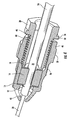
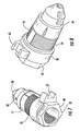
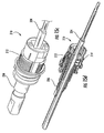
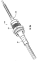
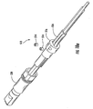
- the cable attachment 10 comprises an adapter body 12, a grip device 14, a grommet device 16, a washer 18, and a bolt portion 20. Also shown in FIGS. 1 and 2 is an optional plug 22 that is selectively provided to occupy the opening of the cable attachment when a cable is not inserted in the cable attachment to prevent the ingress of water, dirt, moisture, infestation, or other undesirable matter into the closure prior to insertion of a cable.
- the plug 22 is configured to be inserted into the cable attachment 10 a predetermined axial distance (which is limited by one or more collars shown in FIGS. 1-2 ) such that the plug is engaged by the grommet device 16 but not the grip device 14, as insertion of the plug into the grip device could damage the grip device and complicate removal of the plug.
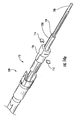
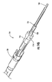
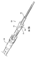
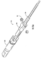
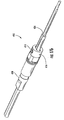
- FIGS. 3 and 4 illustrate the cable attachment 10 used with a cable 24 that includes a jacket 26 that has been stripped to expose the required length of buffer tube 28 and optical fiber (not shown) within the buffer tube to enable the technician to splice, connect, or perform other operations on the optical fiber within the closure either before or after the cable has been sealed and retained by the cable attachment.
- further embodiments of the present invention include cable attachments that do not require the cable to be stripped or provide for the cable to be stripped at any axial location of the cable relative to the cable attachment.
- the adapter body 12 of the cable attachment 10 of FIGS. 1-8 comprises a unitary component made of thermoplastic material; however, further embodiments of the present invention may be made of any number of components and of alternative materials such as metal to list an additional non-limiting example.
- the adapter body 12 of FIGS. 1-8 includes a first axial end 30 and a second axial end 32 generally opposed to the first axial end.
- the adapter body 12 provides at least one opening 34 sized to allow passage of at least one cable 24 through the adapter body in a generally axial direction.
- the opening 34 of the adapter body 12 may be completely encircled by the adapter body, such as with a through hole, or the opening may be partially encircled, such as with a slotted opening, channel, or the like, to give non-limiting examples of openings through the adapter body.
- the adapter body 12 defines a generally cylindrical shape with a frustoconical first axial end 30, an exterior threaded portion 36, a collar portion 38, and a hex portion 40; however, further embodiments of the present invention comprise alternative and/or additional shapes and/or features as suited for the particular closure and/or cable.
- the frustoconical first axial end 30 of the adapter body 12 is in part provided to create a lead-in surface 42, as shown in FIG.
- the frustoconical first axial end 30 also provides an area for the prongs of the grip device of the illustrated embodiment to move during insertion of the cable 24, as described in more detail below.
- the area inside the frustoconical first axial end 30 also allows portions of the cable proximate the stripped jacket, such as strength members extending from the jacket (described below), to have room to expand and contract based upon temperature variations.
- the opening of the first axial end 30 of the adapter body 12 defines a smaller cross-sectional area relative to the cross-sectional area of the opening of the second axial end 32 of the adapter body.
- the exterior threaded portion 36 of the adapter body is configured to pass through the opening of the closure and to be retained by the closure such that an interior portion of the adapter body at the first axial end of the adapter body is located inside the closure and an exterior portion at the second axial end of the adapter body is located outside the closure. More specifically, the first axial end 30 of the adapter body 12 is passed through the opening of the closure until the closure wall engages the collar portion 38.
- a retention device (not shown) that includes internal threading corresponding to the threading of the exterior threaded portion is inserted over the first axial end 30 of the adapter body and threaded toward the second axial end 32 until the retention device engages the interior of the closure to selectively retain the adapter body within the opening of the closure.
- Further embodiments of the present invention provide alternative structures and/or devices for retaining the adapter body and/or cable attachment relative to the closure.
- the illustrated embodiments of the present invention show the cable attachment configured for positioning within the opening of the closure; however, still further embodiments of the present invention are configured to position the adapter body and/or other components of the cable attachment adjacent the opening of the closure with or without any portion of the cable attachment passing through the opening of the closure.
- "adjacent" is intended to mean that the adapter body is positioned near the opening and/or within the opening of the closure.
- the hex portion 40 of the adapter body 12 of the cable attachment 10 of FIGS. 1-8 is positioned opposite the collar portion 38 from the threaded exterior portion 36.
- the hex portion 40 is provided on the exterior body 12 to enable a technician to prevent the adapter body from rotating during insertion and/or rotation of the bolt portion 20 of the illustrated embodiment.
- the opening 34 of the adapter body 12 extends from the axial second end 32 to the first axial end 30 a certain axial distance, and the adapter body defines a threaded interior portion 44 along the opening 34.
- the bolt portion 20 defines a threaded exterior portion 46 along an exterior surface of the bolt portion that corresponds to the threaded interior portion 44 of the opening of the adapter body 12, such that the bolt portion can be selectively threaded into the adapter body.
- the hex portion 40 of the adapter body 12 may be clamped with a wrench by the technician while the technician threads the bolt portion 20 into the opening 34 of the adapter body 12 to keep the adapter body from unintentionally rotating.
- Further embodiments of the present invention provide alternative devices on the exterior and/or interior of the adapter body and/or bolt portion to allow a technician to conveniently move the bolt portion relative to the adapter body. Still further embodiments provide alternative shapes and/or features to enable the bolt portion and adapter body to be moved relative to one another and retained relative to one another.
- the grip device 14 of the cable attachment 10 of FIGS. 1-4 and 10a-13 includes at least one aperture 48 sized to grip at least a portion of an outer surface of the cable 24.
- the aperture 48 of the grip device may be completely closed, such as a through hole, or partially enclosed, such as a slotted opening, channel, or the like, to give non-limiting examples of grip device apertures.
- the grip device 14 of FIGS. 1-4 and 10a-13 comprises a grip washer, wherein the grip washer further comprises at least one prong 50 for engaging the at least a portion of an outer surface of the cable 24.
- the grip device 14 includes a plurality of generally radial slits extending from the aperture 48 a certain distance toward the perimeter of the grip device.
- the prongs 50 of the grip device 14 are defined between the generally radial slits.
- the prongs 50 also include an angled portion 52, such that a radially inward portion of the prongs are angled in one axial direction.
- the angled portions 52 of the prongs 50 provide for easy insertion of a cable 24 through the aperture 48; however, the angled portions of the prongs grip at least a portion of an outer surface of the cable to prevent the cable from being removed from the grip device in an opposite direction from which it was inserted.
- the grip device 14 is sized to allow insertion of the cable 24 through the aperture 48 with one to five pounds of force in an axial direction; however, removal of the cable from the aperture of the grip device requires approximately 222N (fifty pounds) or more of force in an opposite axial direction.
- the grip device 14 retains the cable 24 inserted into the cable attachment and provides strain relief such that once the cable has been properly installed in the cable attachment and the one or more fibers connected within the closure, an axial force exerted on the cable external to the closure will be distributed through the cable attachment to minimize and/or prevent damage to the one or more fiber connections within the closure.
- Further embodiments of the present invention provide alternative designs for the grip washer illustrated in FIGS. 1-4 and 10a-13, while further comparative embodiments provide alternative grip devices, such as the grip devices of FIGS. 15a - 18d, to provide a number of non-limiting examples.
- Some embodiments of the cable attachment and closure of the present invention are configured to be used with grounded cables.
- the cable inserted into the cable attachment and closure may comprise a metallic armor, a metallic strength member, or other component that defines a ground.
- the cable attachment is configured to pierce the jacket of the cable such that an electrically conductable portion of the cable attachment electrically engages the armor or strength member of the cable to thereby ground the cable attachment
- the cable attachment of some embodiments of the present invention comprise electrically conductable leads that electrically join the cable ground to the closure to thereby ground the closure.
- a grounded cable attachment comprises a grip device that pierces the jacket a sufficient amount to electrically contact the armor and/or strength member to thereby ground the grip device.
- the grounded grip device is further connected to an electrical conductor, such as a conductor extending radially through the adapter body to provide one non-limiting example, that is in electrical communication with at least part of the closure.
- an electrical conductor such as a conductor extending radially through the adapter body to provide one non-limiting example, that is in electrical communication with at least part of the closure.
- Still further embodiments of the present invention comprise alternative devices and configurations to ground the cable attachment and closure when grounded cables are provided.
- the grip device 14 of FIGS. 1-4 and 10a-13 is configured to be inserted into the opening 34 of the adapter body 12, and is inserted with the prongs 52 angled toward the first axial end 30 of the adapter body 12 for the embodiment of FIGS. 1-8 (to insert the grip device with the prongs in the opposite direction would prevent the cable from passing through, and being engaged by, the grip device); however, further embodiments may orient the grip device in an alternative direction.
- Opposite the first axial end 30 of the grip device 14 is provided a grommet device 16 within the opening of the adapter body proximate the grip device.
- the grommet device 16 of FIGS. 1-8 defines a generally cylindrical shape with a passageway therethrough to allow the cable to traverse the grommet device in a generally axial direction.
- "traverse" means that the cable passes through and/or around the grommet device.
- the grommet device 16 of FIGS. 1-8 comprises an elastomeric material, examples include but are not limited to silicone materials, neoprene materials, and ethylene propylene diene monomer (EPDM), that is easily deformable relative to the thermoplastic material of the adapter body and bolt portion and to the metal of the grip device 14; however, further embodiments of the cable attachment provide grommet devices of alternative material.
- the grommet device 16 is intended to change shape when exposed to forces, such as compressive forces in the illustrated embodiment. For the grommet device 16 of FIGS.
- the cable attachment 10 of FIGS. 1-8 is preferably configured to provide a sealing engagement of the grommet device 16 about the outer surface of the cable 24, such that water, moisture, dirt, infestation, and/or other undesirable material are not able to enter the closure through the cable attachment. Additional embodiments of the present invention provide alternative grommet devices of different shapes, materials, and/or sizes such that one or more forces exerted upon the grommet device enables the grommet device to partially or completely provide a seal about an outer surface of a cable.
- the grommet device of various embodiments of the present invention comprises one or more keyed portions along an exterior wall of the grommet that engages the opening of the adapter body.
- the opening of the adapter body also includes one or more keyed slots adapted to receive the keyed portions, such that the grommet device can be rotationally retained within the adapter body.
- the grommet device of such embodiments of the cable attachment includes a passageway that defines a cross-section, such as elliptical to provide one non-limiting example, that is adapted to receive a cable that defines a corresponding cross-section. Because the grommet is rotationally fixed relative to the adapter body and the adapter body is rotationally fixed relative to the closure in some embodiments of the invention (see discussion of FIGS.
- cables having non-circular cross-sections can be inserted into the cable attachments in a preferred orientation such that the portions of the one or more cables exterior to the closure can be conveniently routed in a desired direction to minimize damage to the fibers or minimize stresses created on the cable when bending.
- Further embodiments of the present invention comprise alternative features and configurations to provide convenient routing of the cables exterior to the closure.
- the washer 18 is provided in the embodiment of FIGS. 1-8 to provide protection for the grommet device 16 from wear on the axial surface that engages the bolt portion 20. Additional embodiments of the present invention provide alternative devices to protect the grommet device and/or provide grommet devices that do not need protection. Further embodiments of the present invention may provide on the bolt portion a surface of a particular shape, material, or texture for minimizing damage to the grommet device. Still further embodiments of the present embodiment may omit the washer and other components for protection of the grommet device.
- the bolt portion 20 of the cable attachment 10 of FIGS. 1-4 comprises a unitary component made of thermoplastic material, preferably the same material as used in the adapter body 12; however, further embodiments of the present invention may be made of alternative materials such as metal to list an additional non-limiting example.
- the bolt portion 20 of FIGS. 1-4 is generally shaped similar to a conventional bolt, bolt portions of further embodiments of the present invention comprise shapes and features that do not necessarily resemble a bolt portion.
- the bolt portion of the present invention is any component that is selectively moveable, relative to the adapter body, to provide a force on the grommet device regardless of shape, size, location or orientation of the cable relative to the bolt portion, or any other feature of the bolt portion. Turning again to the bolt portion 20 of FIGS.
- the bolt portion comprises a through hole that defines an axis that is generally aligned with an axis of the grommet device; however further embodiments of the bolt portion comprise through holes of any shape and orientation.
- the bolt portion 20 is configured to engage the adapter body 12, such as by threading the bolt portion into the opening 34 of the adapter body to describe one non-limiting example of engagement between the bolt portion and adapter body.
- the bolt portion 20 preferably has a collar 56 at an axial end of the threaded exterior portion 46, which preferably limits the distance that the bolt portion may be threaded into the adapter body 12.
- Further embodiments of the cable attachment of the present invention comprise bolt portions with removable washers or other devices for selectively adjusting the amount of travel the bolt portion may make relative to the adapter body.
- the bolt portion 20 of the cable attachment 10 of FIGS. 1 - 4 by threading the bolt portion into the opening 34 of the adapter body 12, the bolt portion selectively applies a force upon the grommet device 16 (through the washer 18 ) such that the grommet device engages the outer surface of the cable 24.
- the bolt portion 20 of FIGS. 1-4 applies a compressive force upon the grommet device 16 to cause the inner diameter of the grommet device to decrease and create a seal about the outer surface of the cable; however, further embodiments of the present invention provide alternative bolt portions that define alternative engagements with the adapter body to provide different forces upon the grommet device in order to cause the grommet device to engage the outer surface of the cable.
- the technician if the cable attachment is not already positioned within the opening of the closure, the technician preferably accesses the closure to remove any component that may be occupying or obstructing the opening of the closure, such as a grommet.
- the technician axially inserts the adapter body (which may or may not be attached to the other portions of the cable attachment) from outside the closure until the collar portion engages the exterior wall of the closure proximate the opening.
- the technician then threads on the retention device (not shown) on the interior portion of the adapter body until the adapter body is axially secured in the opening of the closure.
- the technician rotates the bolt portion away from the adapter body such that the passageway of the grommet device is opened sufficiently for a cable to pass therethrough. If a plug 22 is provided in the cable attachment 10, it may be removed from the cable attachment once the passageway has been sufficiently opened, and the plug may be discarded or saved for subsequent use.
- the technician then feeds the cable 24 through the cable assembly 10, such as is shown in FIGS. 3 and 4 until the cable defines the desired axial position, e.g., the amount of cable fed into the closure is a sufficient amount to enable the technician to perform the necessary fiber optic joining operation, such as splicing and/or connectorizing.
- the technician may feed the cable axially through the bolt portion, the washer 18 (if desired), the grommet device 16, the grip device 14, and then through the adapter body and then insert the grip device, grommet device, washer, and bolt portion in the opening of the adapter body and then thread the bolt portion into the adapter body to define the assembled cable attachment.
- Further embodiments of the present invention comprise alternative and/or additional procedures for installing the cable attachment in the closure and/or passing the cable through the cable attachment.
- the cable attachment 10 may be used with cables 24 that include a jacket 26 (and other components such as strength members to list one example) about one or more buffer tubes 28, such that the jacket may be selectively stripped from the buffer tube at a desired axial position, such as is illustrated in FIG. 3 .
- Alternative embodiments of the present invention include cable attachments for use with non-stripped cables.
- the cable attachment 10 of the embodiment illustrated in FIGS. 1-8 is configured to accept stripped cables 24 as the opening of the first axial end 30 of the adapter body 12 is sized to allow passage of only the buffer tube 28 of the cable.
- the technician should ensure that the grip device 14 has gripped at least a portion of the outer surface of the jacket 26 of the cable, as the buffer tube 28 defines a diameter too small to be gripped by the prongs 50 of the grip device.
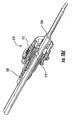
- one or more windows 60 are provided within the first axial end 30, such that a portion of the at least one opening of the adapter body is visible from a generally radial direction relative to an axis of the at least one opening of the adapter body.
- the windows 60 are located between the opening of the first axial end 30 of the adapter body 12 and the fully installed grip device 14 so that the technician may be able to see that the jacket 26 of the cable 24 has passed through the grip device such that the cable is adequately retained and/or strain relieved by the cable attachment.
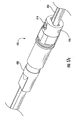
- FIG. 5 illustrates an installed cable in which only the buffer tube 28 is visible through the window 60, thus indicating to the technician that the cable 24 should be inserted axially further into the cable attachment as the grip device 14 may not be engaging the outer surface of the cable.
- FIG. 6 illustrates a properly installed cable 24 in which the technician can verify that the jacket 26 has passed through the grip device 14 a sufficient axial length to provide the desired retention and/or strain relief.
- the adapter body 12 includes a tab portion 62 defined on an exterior surface of the adapter body, such that the tab portion rotationally fixes the adapter body relative to the closure, which is particularly helpful when the technician is threading the retention device (not shown) to axially secure the adapter body to the closure, as shown if FIGS. 9a and 9b , and when the technician is rotating the bolt portion 20 relative to the adapter body to selectively apply and remove forces on the grommet device 16.
- the tab portion 62 of the illustrated embodiment comprises slot into which a protrusion on the closure engages to prevent rotation of the adapter body relative to the closure.
- Alternative embodiments of the present invention comprise alternative tab portions configured to rotationally fix the adapter body relative to the closure.
- FIGS. 9a and 9b Two closures 64 of slightly different designs are illustrated in FIGS. 9a and 9b , wherein each closure has eight openings that have cable attachments 10 positioned adjacent thereto, or more specifically, positioned within the openings.
- the cable attachments 10 are illustrated without cables 24 or plugs 22 inserted therein.
- the cable attachments of FIGS. 9a and 9b are fully installed such that the tab portion 62 of each adapter body 12 engages a protrusion 66 of the closure 64, such that each adapter body is rotationally fixed relative to the closure.
- Further embodiments of the present invention comprise closures having at least one opening and/or defining alternative protrusions configured to rotationally fix adapter bodies installed proximate thereto.
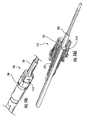
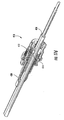
- FIGS. 10a-13 the grip device 14 is shown from a number of vantage points to illustrate the grip provided by the prongs 50 of the grip device.
- the jacket 26 of the cable 24 defines an elliptical cross-section, only four of the eight prongs 50 of the grip device 14 grip the outer surface of the cable; however, enough grip is provided by the four prongs of the grip device to provide the desired retention and/or strain relief for the embodiment shown in FIGS. 1-13 .
- Further embodiments of the present invention comprise alternative grip devices adapted for specific cable cross-sections and/or alternative designs for gripping the cable.
- FIGS. 14a - 18d Comparative embodiments of the present invention are provided in FIGS. 14a - 18d, wherein alternative cable attachments 110-510 are illustrated.
- the cable attachment 110 of FIGS. 14a-14d includes a jacket piercing grip device 114, which may also be known as an insulation displacement contact ("IDC").
- the grommet device 116 which may or may not provide a sealing engagement with the outer surface of the cable, is axially positioned along the cable 124.
- the grommet device 116 of the embodiment of FIGS. 14a-14d is a retainer insert and does not provide a sealing engagement with the outer surface of the cable 124; however, a seal is provided by the cable attachment 110 with a heat shrink portion, as discussed below.
- One or more jacket piercing grip devices 114 are inserted into one or more generally radially oriented slots until the grip devices pierce the jacket of the cable 124 and preferably engage the strength members of the cable to improve the retention and/or strain relief of the cable attachment 110.
- the technician may need to use pliers or other equipment to fully engage the grip device 114 with the cable 124 to grip the cable.
- a bolt portion 120 which comprises a retainer body in the embodiment of FIGS. 14a-14d , is then axially advanced to generally enclose the grommet device 116.
- the bolt portion 120 of FIGS. 14a-14d preferably includes a heat shrink portion that may be shrunk once the bolt portion is in position to provide a seal for the cable attachment 110.
- the bolt portion 120 may include a threaded portion to engage the adapter body or other features to selectively engage the adapter body.
- features for selective engagement of the bolt portion and adapter body includes a bolt portion and adapter body configured to replicate the OPTITAP TM connectors available from Corning Cable Systems LLC of Hickory, NC.
- the cable attachment 210 of FIGS. 15a-15d is comparable to the cable attachment 110 of FIGS. 14a-14d but with the addition of an extra set of jacket piercing grip devices 214.
- the cable attachment 310 of FIGS. 16a-16d is similar to the cable attachment 110 of FIGS. 14a - 14d but the cable attachment 310 includes the jacket piercing grip devices 314 that define a U-shaped design such that a single grip device 314 is capable of gripping the outer surface of the cable in at least two locations.
- the cable attachment 410 of FIGS. 17a - 17d is also similar to the cable attachment 110 of FIGS.
- the grip device 414 comprises a single set screw that is threaded into the grommet device 416 to grip the outer surface of the cable 424.
- the cable attachment 510 of FIGS. 18a-18d comprises a grip device 514 of two set screws for gripping the outer surface of the cable 524.
Landscapes
- Physics & Mathematics (AREA)
- General Physics & Mathematics (AREA)
- Optics & Photonics (AREA)
- Cable Accessories (AREA)
- Installation Of Indoor Wiring (AREA)
- Insulating Bodies (AREA)
- Connection Or Junction Boxes (AREA)
- Light Guides In General And Applications Therefor (AREA)
- Ropes Or Cables (AREA)
- Insertion, Bundling And Securing Of Wires For Electric Apparatuses (AREA)
Claims (16)
- Kabelbefestigung (10) zum Abdichten und Halten eines Kabels, das durch eine in einem Telekommunikationsverschluss definierte Öffnung in den Verschluss eintritt, wobei die Kabelbefestigung (10) Folgendes umfasst:einen Adapterkörper (12), der zur Positionierung neben der Öffnung des Verschlusses konfiguriert ist, wobei der Adapterkörper (12) ein erstes axiales Ende (30) und ein zweites axiales Ende (32), das dem ersten axialen Ende allgemein gegenüberliegt, definiert, und wobei der Adapterkörper (12) mindestens eine Öffnung (34) bereitstellt, die so bemessen ist, dass sie das Passieren mindestens eines Kabels gestattet;eine Klemmvorrichtung (14), die in der mindestens einen Öffnung (34) des Adapterkörpers (12) vorgesehen ist, wobei die Klemmvorrichtung (14) einen Durchbruch (48) definiert, der so bemessen ist, dass er mindestens einen Teil einer Außenfläche des Kabels eingeklemmt;eine Tüllenvorrichtung (16), die in der mindestens einen Öffnung (34) des Adapterkörpers (12) und nahe der Klemmvorrichtung (14) vorgesehen ist, wobei die Tüllenvorrichtung (16) einen Durchgang (54) definiert, um dem Kabel zu gestatten, die Tüllenvorrichtung (16) in einer allgemein axialen Richtung bezüglich des Kabels zu durchqueren; und einen Schraubenteil (20), der dazu konfiguriert ist, den Adapterkörper (12) in Eingriff zu nehmen, wobei der Schraubenteil (20) dazu ausgeführt ist, eine Kraft gezielt an die Tüllenvorrichtung (16) anzulegen, so dass die Tüllenvorrichtung (16) die Außenfläche des Kabels in Eingriff nimmt,dadurch gekennzeichnet, dass
das erste axiale Ende des Adapterkörpers (12) mindestens ein Fenster (60) umfasst, so dass ein Teil der mindestens einen Öffnung des Adapterkörpers (12) aus einer allgemein radialen Richtung bezüglich einer Achse der mindestens einen Öffnung des Adapterkörpers sichtbar ist, wobei das oder jedes Fenster (60) so angeordnet ist, dass es eine Verifikation gestattet, dass ein nicht abgemantelter Teil des Kabels durch die Klemmvorrichtung (14) passiert ist, um eine gewünschte Halterung und/oder Zugentlastung bereitzustellen. - Kabelbefestigung nach Anspruch 1, wobei die mindestens eine Öffnung (34) des Adapterkörpers (12) so bemessen ist, dass sie das Passieren mindestens eines Lichtwellenleiters gestattet.
- Kabelbefestigung nach Anspruch 1, wobei der Adapterkörper (12) an einem ersten axialen Ende (30) einen Innenteil und an einem zweiten axialen Ende (32), das dem ersten axialen Ende allgemein gegenüberliegt, einen Außenteil definiert, wobei der Adapterkörper (12) dazu konfiguriert ist, die Öffnung des Verschlusses zu passieren und durch den Verschluss so festgehalten zu werden, dass sich der Innenteil des Adapterkörpers (12) innerhalb des Verschlusses und der Außenteil des Adapterkörpers außerhalb des Verschlusses befindet.
- Kabelbefestigung nach Anspruch 3, wobei die mindestens eine Öffnung (34) des Adapterkörpers (12) eine kleinere Querschnittsfläche als das erste axiale Ende (30) bezüglich der Querschnittsfläche der mindestens einen Öffnung an dem zweiten axialen Ende (32) definiert.
- Kabelbefestigung nach Anspruch 1, wobei die Klemmvorrichtung (14) eine Klemmscheibe umfasst.
- Kabelbefestigung nach Anspruch 1, wobei die Klemmvorrichtung (14) mindestens eine Stellschraube umfasst.
- Kabelbefestigung nach Anspruch 1, wobei die Klemmvorrichtung (14) mindestens einen Stift (50) zur Ineingriffnahme mindestens eines Teils der Außenfläche des Kabels umfasst.
- Kabelbefestigung nach Anspruch 1, wobei der Durchgang (54) der Tüllenvorrichtung (16) ein Durchgangsloch umfasst, das eine Achse definiert, die auf eine Achse des Adapterkörpers (12) allgemein ausgerichtet ist.
- Kabelbefestigung nach Anspruch 1, wobei der Durchgang (54) der Tüllenvorrichtung (16) einen nicht kreisförmigen Querschnitt definiert und wobei die Tüllenvorrichtung (16) einen keilverzahnten Teil umfasst, so dass die Tüllenvorrichtung bezüglich des Adapterkörpers (12) gezielt ausgerichtet werden kann.
- Kabelbefestigung nach Anspruch 1, die weiterhin einen Stopfen (22) umfasst, der durch mindestens die Tüllenvorrichtung (16) gezielt festgehalten wird, um die Kabelbefestigung vor Eintritt des Kabels in den Verschluss abzudichten.
- Kabelbefestigung nach Anspruch 1, wobei der Adapterkörper (12) mindestens einen Nasenteil enthält, der an einer Außenfläche des Adapterkörpers ausgebildet ist, so dass der Nasenteil den Adapterkörper bezüglich des Verschlusses drehfixiert.
- Kabelbefestigung nach Anspruch 1, wobei der Adapterkörper (12) einen mit einem Gewinde versehenen Innenteil und der Schraubenteil einen mit einem Gewinde versehenen Außenteil definiert, so dass der Schraubenteil gezielt in den Adapterkörper geschraubt werden kann.
- Telekommunikationsvorrichung, die Folgendes umfasst:einen Verschluss, der mindestens eine Öffnung definiert;eine Kabelbefestigung (10) nach einem der Ansprüche 1 bis 12,wobei die Kabelbefestigung (10) dazu ausgeführt ist, ein durch die mindestens eine Öffnung, die in dem Verschluss definiert ist, in den Verschluss eintretendes Kabel abzudichten und festzuhalten.
- Verfahren zum Einführen eines Kabels in einen Telekommunikationsverschluss durch eine Kabelbefestigung (10) nach einem der Ansprüche 1 bis 12, das Folgendes umfasst:Einführen des Kabels durch den Schraubenteil (20), den Durchgang (54) der Tüllenvorrichtung (16), den Durchbruch der Klemmvorrichtung (14) und eine Öffnung eines Adapterkörpers (12);Bewegen des Schraubenteils (20) der Kabelbefestigung (10) bezüglich des Adapterkörpers (12) der Kabelbefestigung (10);optisches Verifizieren durch das oder jedes Fenster (60) im Adapterkörper (12), dass ein nicht abgemantelter Teil des Kabels die Klemmvorrichtung (14) durchquert hat, um eine gewünschte Halterung und/oder Zugentlastung bereitzustellen.
- Verfahren nach Anspruch 14, das weiterhin Folgendes umfasst:Abmanteln mindestens einen Außenteils des Kabels vor dem Einführen des Kabels zur Definition eines abgemantelten Teils des Kabels und eines nicht abgemantelten Teils des Kabels, so dass nur der abgemantelte Teil des Kabels durch eine Öffnung des Adapterkörpers (12) eingeführt wird, wenn das Kabel durch den Schraubenteil (20), den Durchgang der Tüllenvorrichtung (16), den Durchbruch der Klemmvorrichtung (14) und die Öffnung des Adapterkörpers (12) eingeführt wird.
- Verfahren nach Anspruch 14, das weiterhin:Entfernen eines Stopfens (22) von der Kabelbefestigung vor Einführen des Kabels umfasst.
Applications Claiming Priority (2)
| Application Number | Priority Date | Filing Date | Title |
|---|---|---|---|
| US70296505P | 2005-07-27 | 2005-07-27 | |
| PCT/US2006/029740 WO2007014385A2 (en) | 2005-07-27 | 2006-07-27 | Sealing and retaining cable attachment for telecommunications closures |
Publications (2)
| Publication Number | Publication Date |
|---|---|
| EP1907897A2 EP1907897A2 (de) | 2008-04-09 |
| EP1907897B1 true EP1907897B1 (de) | 2009-07-01 |
Family
ID=37496788
Family Applications (1)
| Application Number | Title | Priority Date | Filing Date |
|---|---|---|---|
| EP06788991A Active EP1907897B1 (de) | 2005-07-27 | 2006-07-27 | Abdichtende und zugentlastete kabeldurchführung für telekommunikations-gehäuse |
Country Status (12)
| Country | Link |
|---|---|
| US (2) | US7568943B2 (de) |
| EP (1) | EP1907897B1 (de) |
| JP (1) | JP4982491B2 (de) |
| CN (1) | CN101248381B (de) |
| AT (1) | ATE435437T1 (de) |
| AU (1) | AU2006272477B2 (de) |
| CA (1) | CA2616752C (de) |
| DE (1) | DE602006007586D1 (de) |
| ES (1) | ES2328958T3 (de) |
| MX (1) | MX2008001299A (de) |
| PT (1) | PT1907897E (de) |
| WO (1) | WO2007014385A2 (de) |
Cited By (1)
| Publication number | Priority date | Publication date | Assignee | Title |
|---|---|---|---|---|
| USRE45951E1 (en) | 2007-01-16 | 2016-03-29 | Commscope Technologies Llc | Cable enclosure assemblies and methods for using the same |
Families Citing this family (48)
| Publication number | Priority date | Publication date | Assignee | Title |
|---|---|---|---|---|
| EP1894074A4 (de) * | 2005-06-13 | 2010-05-19 | Sigma Systems Corp | Verfahren und vorrichtung zur optimierung von umgebungsfeuchtigkeit |
| MY151524A (en) * | 2006-03-20 | 2014-05-30 | Temptronic Corp | Temperature-controlled enclosures and temperature control system using the same |
| US7738759B2 (en) * | 2007-03-16 | 2010-06-15 | 3M Innovative Properties Company | Optical fiber cable inlet device |
| US7668431B2 (en) * | 2007-04-10 | 2010-02-23 | Corning Cable Systems Llc | Grommet and plate assembly for sealing fiber optic closures |
| US8039745B2 (en) * | 2007-08-01 | 2011-10-18 | Panduit Corp. | Cable strain relief module assembly |
| CN101910902B (zh) * | 2007-11-19 | 2012-10-03 | 3M创新有限公司 | 通信电缆入口设备 |
| WO2009126411A1 (en) * | 2008-04-09 | 2009-10-15 | 3M Innovative Properties Company | Telecommunications cable inlet device |
| US7580608B1 (en) | 2008-04-29 | 2009-08-25 | Corning Cable Systems Llc | Pushing-in fiber optic cable driver |
| US20090273945A1 (en) * | 2008-04-30 | 2009-11-05 | Megapull, Inc. | Modular, luminous, small form-factor solid-state lighting engine |
| WO2010014476A2 (en) * | 2008-08-01 | 2010-02-04 | 3M Innovative Properties Company | Optical fiber cable inlet device with integral optical device |
| CN102257681B (zh) | 2008-11-07 | 2013-09-04 | 富加宜汽车控股公司 | 密封的电连接器 |
| US7672562B1 (en) * | 2009-02-27 | 2010-03-02 | Ofs Fitel, Llc | Optical cable having an enlarged section to facilitate pulling |
| CN102422194B (zh) * | 2009-05-08 | 2015-12-16 | Adc电信公司 | 电缆牵引组件 |
| DE202009006991U1 (de) * | 2009-05-14 | 2009-07-23 | CCS Technology, Inc., Wilmington | Kabelmuffe |
| EP2355283A1 (de) | 2010-01-29 | 2011-08-10 | Tyco Electronics Raychem BVBA | Kabelabdichtungsvorrichtung, Kabelabschluss und Befestigungsvorrichtung |
| EP2355285A1 (de) | 2010-01-29 | 2011-08-10 | Tyco Electronics Raychem BVBA | Kabelabdichtungs- und Befestigungsvorrichtung und Kabelverbindung |
| EP2355286B1 (de) | 2010-01-29 | 2019-04-03 | CommScope Connectivity Belgium BVBA | Kabelabdichtungs- und Befestigungsvorrichtung |
| US8317548B2 (en) * | 2010-05-26 | 2012-11-27 | Phoenix Contact Gmbh & Co. Kg | Electrical connector |
| US8917966B2 (en) | 2010-06-15 | 2014-12-23 | Tyco Electronics Corporation | Cable enclosure systems, plugs and methods for using the same |
| CN103221863B (zh) | 2010-10-28 | 2016-06-01 | 康宁光缆系统有限责任公司 | 抗冲击光纤外壳及相关方法 |
| WO2012162497A1 (en) * | 2011-05-24 | 2012-11-29 | Corning Cable Systems Llc | Three-cable port grommet washer |
| US8686289B2 (en) | 2011-07-14 | 2014-04-01 | Channell Commercial Corporation | Sealing mechanism and method for drop cable splice enclosures |
| US9069151B2 (en) | 2011-10-26 | 2015-06-30 | Corning Cable Systems Llc | Composite cable breakout assembly |
| US8873926B2 (en) | 2012-04-26 | 2014-10-28 | Corning Cable Systems Llc | Fiber optic enclosures employing clamping assemblies for strain relief of cables, and related assemblies and methods |
| EP2680382B1 (de) * | 2012-06-27 | 2015-05-06 | OSRAM GmbH | Verfahren zum Leiten eines elektrischen Kabels durch ein Loch, und Vorrichtung dafür |
| CN103149644B (zh) * | 2013-02-28 | 2015-08-19 | 辽宁省电力有限公司营口供电公司 | 一种耐温耐压光纤适配器及其制作检测工艺 |
| JP6318517B2 (ja) * | 2013-09-24 | 2018-05-09 | オムロン株式会社 | 光ファイバセンサ用光ファイバユニット |
| JP6283990B2 (ja) * | 2013-10-11 | 2018-02-28 | ティアック株式会社 | ケーブル固定装置 |
| CN104703416A (zh) * | 2013-12-05 | 2015-06-10 | 上海搜博实业有限公司 | 一种现场总线型信号分配器 |
| CN103683118A (zh) * | 2013-12-23 | 2014-03-26 | 陈焕祥 | 一种通信线缆的止回器 |
| ES3037493T3 (en) | 2014-11-04 | 2025-10-02 | CommScope Connectivity Belgium BVBA | Enclosure for use in a fiber optic distribution network |
| US10811862B2 (en) * | 2015-05-21 | 2020-10-20 | CommScope Connectivity Belgium BVBA | Sealable cable port assemblies for telecommunications enclosure |
| CN108050145B (zh) * | 2018-01-26 | 2024-04-16 | 国家电网公司 | 一种防溢防转螺栓及其使用方法 |
| EP3791221B1 (de) * | 2018-05-11 | 2023-09-06 | PPC Broadband Fiber Ltd. | Spleissverschluss für fasern |
| US10509178B1 (en) * | 2018-08-31 | 2019-12-17 | Corning Research & Development Corporation | Fiber optic adapter assemblies including a selectively lockable adapter member |
| CN109100136A (zh) * | 2018-09-27 | 2018-12-28 | 哈尔滨理工大学 | 一种用于电缆附件界面压力试验的电缆附件安装方法 |
| US11092754B2 (en) * | 2019-02-08 | 2021-08-17 | Clearfield, Inc. | Protective cap for an optical fiber connector |
| US10782481B1 (en) * | 2019-03-13 | 2020-09-22 | The Boeing Company | Optical fasteners having heads with lenses |
| US11220321B2 (en) | 2019-03-13 | 2022-01-11 | The Boeing Company | Window systems including optical fasteners |
| CN109828180A (zh) * | 2019-04-03 | 2019-05-31 | 哈尔滨理工大学 | 一种实验用电缆附件装拆装置及工作方法 |
| EP3970245B1 (de) * | 2019-05-17 | 2023-11-29 | Metzner Maschinenbau GmbH | Verfahren, vorrichtung und system zur konfektionierung eines elektrischen kabels |
| CN110571012B (zh) * | 2019-09-23 | 2021-07-20 | 中国科学院合肥物质科学研究院 | 一种超导磁体接头盒全焊透结构 |
| US11460655B2 (en) | 2020-02-16 | 2022-10-04 | Corning Research & Development Corporation | Cable entry sealing systems for telecommunication enclosures |
| WO2021167695A1 (en) * | 2020-02-20 | 2021-08-26 | Amphenol Corporation | Coupling mechanism and connector with the same |
| JP2023527519A (ja) * | 2020-05-20 | 2023-06-29 | コムスコープ テクノロジーズ リミティド ライアビリティ カンパニー | アクティブ光ケーブルアセンブリー |
| US11934015B2 (en) | 2020-06-09 | 2024-03-19 | Senko Advanced Components, Inc. | Multiport assembly and associated components |
| US12487426B2 (en) * | 2021-11-30 | 2025-12-02 | Corning Research & Development Corporation | Cable attachment device |
| CN118915243B (zh) * | 2024-10-10 | 2025-03-21 | 杭州华宏通信设备有限公司 | 一种光纤活动连接器锁紧机构 |
Family Cites Families (33)
| Publication number | Priority date | Publication date | Assignee | Title |
|---|---|---|---|---|
| DE1196745B (de) | 1962-06-27 | 1965-07-15 | Grossauer Alfred | Einfuehrung elektrischer Leiter in Einfuehrungs-stutzen elektrischer Geraete u. dgl. |
| GB1177404A (en) * | 1967-03-31 | 1970-01-14 | Light & Power Accessories Comp | Cable Gland for Electric Cable |
| DE6601559U (de) | 1968-07-18 | 1969-03-20 | Wilhelm Geissel Metallwarenfab | Kabelverschraubung |
| US3667783A (en) * | 1970-07-08 | 1972-06-06 | Thomas & Betts Corp | Liquid tight strain relief connector |
| DE2934053C2 (de) | 1979-08-23 | 1981-07-09 | Wilhelm Sihn jr. KG, 7532 Niefern-Öschelbronn | Anschlußeinrichtung für Koaxialkabel |
| FR2480026B1 (de) * | 1980-04-08 | 1983-09-23 | Boulay Ste Indle | |
| DE8116716U1 (de) | 1981-06-05 | 1982-11-18 | OBO Bettermann oHG, 5750 Menden | Kabelverschraubung |
| US4358079A (en) * | 1981-10-15 | 1982-11-09 | Pass And Seymour, Inc. | Moisture resistant clamp for portable cables |
| JPS62193206U (de) * | 1986-05-29 | 1987-12-08 | ||
| US4787706A (en) * | 1987-02-03 | 1988-11-29 | American Telephone And Telegraph Company, At&T Bell Laboratories | Duplex optical fiber connector |
| USRE33611E (en) * | 1988-07-01 | 1991-06-11 | Molex Incorporated | Environmentally sealed grounding backshell with strain relief |
| US5042901A (en) * | 1990-07-31 | 1991-08-27 | Siecor Corporation | Preconnectorized optical splice closure |
| US5055056A (en) * | 1990-11-16 | 1991-10-08 | Electric Motion Company, Inc. | Ground wire connector |
| US5337385A (en) * | 1991-03-01 | 1994-08-09 | The Whitaker Corporation | Optical waveguide terminating device |
| US5235138A (en) * | 1991-06-24 | 1993-08-10 | Shah Jagdish H | Penetration plug for pressure vessels |
| US5185844A (en) * | 1991-07-29 | 1993-02-09 | At&T Bell Laboratories | Closure for optical fiber connective arrangements and method of providing same |
| US5378174A (en) * | 1993-03-18 | 1995-01-03 | The Whitaker Corporation | Enclosure for variety of terminal blocks |
| GB9306437D0 (en) * | 1993-03-27 | 1993-05-19 | Hawke Cable Gands Limited | Cable gland |
| US5529522A (en) * | 1995-03-17 | 1996-06-25 | Huang; Chung-Chuan | Electrical connector |
| DE19738517C1 (de) | 1997-09-03 | 1998-11-19 | Hummel Anton Verwaltung | Kabelverschraubung für Erdungs- oder Abschirmkabel mit einem gegen das Kabel preßbaren Klemmeinsatz |
| AU9732998A (en) | 1997-12-22 | 1999-07-12 | Huber & Suhner Ag | Cable sleeve |
| JP3474100B2 (ja) * | 1998-04-10 | 2003-12-08 | カルソニックカンセイ株式会社 | 収納容器 |
| AR019741A1 (es) | 1998-07-15 | 2002-03-13 | Rxs Schrumpftech Garnituren | Cuerpo obturador para guarniciones de cable |
| US6242700B1 (en) * | 1999-01-27 | 2001-06-05 | 3M Innovative Properties Company | End seal assembly for a splice case |
| US6496641B1 (en) * | 1999-08-12 | 2002-12-17 | Bellsouth Intellectual Property Corporation | Fiber optic interface device |
| US20020159709A1 (en) * | 2001-04-27 | 2002-10-31 | Faus Robert J. | Fiber optic bundle matching connector |
| EP1399997B1 (de) | 2001-06-29 | 2005-09-07 | CCS Technology, Inc. | Kabelverschluss |
| JP2003031969A (ja) * | 2001-07-16 | 2003-01-31 | Sony Corp | ケーブル固定装置 |
| US6548761B1 (en) * | 2001-08-10 | 2003-04-15 | Jen-Ching Wang | One-way cable terminal connector |
| US6579014B2 (en) | 2001-09-28 | 2003-06-17 | Corning Cable Systems Llc | Fiber optic receptacle |
| US6962445B2 (en) | 2003-09-08 | 2005-11-08 | Adc Telecommunications, Inc. | Ruggedized fiber optic connection |
| US6926449B1 (en) | 2004-02-23 | 2005-08-09 | Corning Cable Systems Llc | Connector port for network interface device |
| US7044650B1 (en) | 2004-10-22 | 2006-05-16 | Corning Cable Systems Llc | One-piece fiber optic receptacle having chamfer and alignment ribs |
-
2006
- 2006-07-26 US US11/493,733 patent/US7568943B2/en active Active
- 2006-07-27 CN CN200680031170XA patent/CN101248381B/zh not_active Expired - Fee Related
- 2006-07-27 EP EP06788991A patent/EP1907897B1/de active Active
- 2006-07-27 WO PCT/US2006/029740 patent/WO2007014385A2/en not_active Ceased
- 2006-07-27 CA CA2616752A patent/CA2616752C/en active Active
- 2006-07-27 AU AU2006272477A patent/AU2006272477B2/en active Active
- 2006-07-27 AT AT06788991T patent/ATE435437T1/de not_active IP Right Cessation
- 2006-07-27 US US11/498,379 patent/US20070025677A1/en not_active Abandoned
- 2006-07-27 ES ES06788991T patent/ES2328958T3/es active Active
- 2006-07-27 MX MX2008001299A patent/MX2008001299A/es not_active Application Discontinuation
- 2006-07-27 PT PT06788991T patent/PT1907897E/pt unknown
- 2006-07-27 DE DE602006007586T patent/DE602006007586D1/de active Active
- 2006-07-27 JP JP2008524261A patent/JP4982491B2/ja not_active Expired - Fee Related
Cited By (2)
| Publication number | Priority date | Publication date | Assignee | Title |
|---|---|---|---|---|
| USRE45951E1 (en) | 2007-01-16 | 2016-03-29 | Commscope Technologies Llc | Cable enclosure assemblies and methods for using the same |
| USRE46547E1 (en) | 2007-01-16 | 2017-09-12 | Commscope Technologies Llc | Cable enclosure assemblies and methods for using the same |
Also Published As
| Publication number | Publication date |
|---|---|
| CA2616752A1 (en) | 2007-02-01 |
| CA2616752C (en) | 2015-03-24 |
| WO2007014385A2 (en) | 2007-02-01 |
| ATE435437T1 (de) | 2009-07-15 |
| CN101248381A (zh) | 2008-08-20 |
| AU2006272477B2 (en) | 2012-09-06 |
| ES2328958T3 (es) | 2009-11-19 |
| DE602006007586D1 (de) | 2009-08-13 |
| JP2009504122A (ja) | 2009-01-29 |
| EP1907897A2 (de) | 2008-04-09 |
| PT1907897E (pt) | 2009-09-15 |
| CN101248381B (zh) | 2011-02-23 |
| AU2006272477A1 (en) | 2007-02-01 |
| JP4982491B2 (ja) | 2012-07-25 |
| US20070036488A1 (en) | 2007-02-15 |
| US20070025677A1 (en) | 2007-02-01 |
| MX2008001299A (es) | 2008-03-24 |
| US7568943B2 (en) | 2009-08-04 |
| WO2007014385A3 (en) | 2007-03-15 |
Similar Documents
| Publication | Publication Date | Title |
|---|---|---|
| EP1907897B1 (de) | Abdichtende und zugentlastete kabeldurchführung für telekommunikations-gehäuse | |
| RU2595645C2 (ru) | Устройства для кабельного зажима с разгрузкой натяжения кабеля и способов использования таковых | |
| EP2732323B1 (de) | Verschliessmechanismus und verfahren für verbindungskabelspleissgehäuse | |
| EP3660996B1 (de) | Eingangsöffnung für mechanisches kabel | |
| EP3241048B1 (de) | Verbindungsverschraubungsadapter und verwandte verbindungsverschraubungseinheiten und verfahren zum verbinden von verbindungskabeln an faseroptischen gehäusen | |
| US20020064364A1 (en) | Apparatus and method for splitting optical fibers | |
| US11221453B2 (en) | Cable fixation devices and methods | |
| US6591055B1 (en) | Sheath bonding arrangement for fiber optic cable splices | |
| WO2010084343A2 (en) | Improvements in and relating to electrical connector housings | |
| US9057837B2 (en) | End cap, arrangement and kit for terminating a transmission cable | |
| WO2011025869A2 (en) | Strain relief device | |
| WO1997038338A1 (en) | Device for organizing optical fibres | |
| NZ620723B2 (en) | Sealing mechanism and method for drop cable splice enclosures |
Legal Events
| Date | Code | Title | Description |
|---|---|---|---|
| PUAI | Public reference made under article 153(3) epc to a published international application that has entered the european phase |
Free format text: ORIGINAL CODE: 0009012 |
|
| 17P | Request for examination filed |
Effective date: 20080206 |
|
| AK | Designated contracting states |
Kind code of ref document: A2 Designated state(s): AT BE BG CH CY CZ DE DK EE ES FI FR GB GR HU IE IS IT LI LT LU LV MC NL PL PT RO SE SI SK TR |
|
| 17Q | First examination report despatched |
Effective date: 20080716 |
|
| GRAP | Despatch of communication of intention to grant a patent |
Free format text: ORIGINAL CODE: EPIDOSNIGR1 |
|
| GRAS | Grant fee paid |
Free format text: ORIGINAL CODE: EPIDOSNIGR3 |
|
| GRAA | (expected) grant |
Free format text: ORIGINAL CODE: 0009210 |
|
| AK | Designated contracting states |
Kind code of ref document: B1 Designated state(s): AT BE BG CH CY CZ DE DK EE ES FI FR GB GR HU IE IS IT LI LT LU LV MC NL PL PT RO SE SI SK TR |
|
| REG | Reference to a national code |
Ref country code: GB Ref legal event code: FG4D |
|
| REG | Reference to a national code |
Ref country code: CH Ref legal event code: EP |
|
| REG | Reference to a national code |
Ref country code: IE Ref legal event code: FG4D |
|
| REF | Corresponds to: |
Ref document number: 602006007586 Country of ref document: DE Date of ref document: 20090813 Kind code of ref document: P |
|
| REG | Reference to a national code |
Ref country code: PT Ref legal event code: SC4A Free format text: AVAILABILITY OF NATIONAL TRANSLATION Effective date: 20090909 |
|
| REG | Reference to a national code |
Ref country code: ES Ref legal event code: FG2A Ref document number: 2328958 Country of ref document: ES Kind code of ref document: T3 |
|
| PG25 | Lapsed in a contracting state [announced via postgrant information from national office to epo] |
Ref country code: SI Free format text: LAPSE BECAUSE OF FAILURE TO SUBMIT A TRANSLATION OF THE DESCRIPTION OR TO PAY THE FEE WITHIN THE PRESCRIBED TIME-LIMIT Effective date: 20090701 |
|
| NLV1 | Nl: lapsed or annulled due to failure to fulfill the requirements of art. 29p and 29m of the patents act | ||
| PG25 | Lapsed in a contracting state [announced via postgrant information from national office to epo] |
Ref country code: SE Free format text: LAPSE BECAUSE OF FAILURE TO SUBMIT A TRANSLATION OF THE DESCRIPTION OR TO PAY THE FEE WITHIN THE PRESCRIBED TIME-LIMIT Effective date: 20090701 Ref country code: LT Free format text: LAPSE BECAUSE OF FAILURE TO SUBMIT A TRANSLATION OF THE DESCRIPTION OR TO PAY THE FEE WITHIN THE PRESCRIBED TIME-LIMIT Effective date: 20090701 Ref country code: IS Free format text: LAPSE BECAUSE OF FAILURE TO SUBMIT A TRANSLATION OF THE DESCRIPTION OR TO PAY THE FEE WITHIN THE PRESCRIBED TIME-LIMIT Effective date: 20091101 Ref country code: FI Free format text: LAPSE BECAUSE OF FAILURE TO SUBMIT A TRANSLATION OF THE DESCRIPTION OR TO PAY THE FEE WITHIN THE PRESCRIBED TIME-LIMIT Effective date: 20090701 Ref country code: EE Free format text: LAPSE BECAUSE OF FAILURE TO SUBMIT A TRANSLATION OF THE DESCRIPTION OR TO PAY THE FEE WITHIN THE PRESCRIBED TIME-LIMIT Effective date: 20090701 Ref country code: AT Free format text: LAPSE BECAUSE OF FAILURE TO SUBMIT A TRANSLATION OF THE DESCRIPTION OR TO PAY THE FEE WITHIN THE PRESCRIBED TIME-LIMIT Effective date: 20090701 |
|
| PG25 | Lapsed in a contracting state [announced via postgrant information from national office to epo] |
Ref country code: LV Free format text: LAPSE BECAUSE OF FAILURE TO SUBMIT A TRANSLATION OF THE DESCRIPTION OR TO PAY THE FEE WITHIN THE PRESCRIBED TIME-LIMIT Effective date: 20090701 Ref country code: MC Free format text: LAPSE BECAUSE OF NON-PAYMENT OF DUE FEES Effective date: 20090731 Ref country code: NL Free format text: LAPSE BECAUSE OF FAILURE TO SUBMIT A TRANSLATION OF THE DESCRIPTION OR TO PAY THE FEE WITHIN THE PRESCRIBED TIME-LIMIT Effective date: 20090701 Ref country code: PL Free format text: LAPSE BECAUSE OF FAILURE TO SUBMIT A TRANSLATION OF THE DESCRIPTION OR TO PAY THE FEE WITHIN THE PRESCRIBED TIME-LIMIT Effective date: 20090701 |
|
| PG25 | Lapsed in a contracting state [announced via postgrant information from national office to epo] |
Ref country code: BG Free format text: LAPSE BECAUSE OF FAILURE TO SUBMIT A TRANSLATION OF THE DESCRIPTION OR TO PAY THE FEE WITHIN THE PRESCRIBED TIME-LIMIT Effective date: 20091001 |
|
| PG25 | Lapsed in a contracting state [announced via postgrant information from national office to epo] |
Ref country code: RO Free format text: LAPSE BECAUSE OF FAILURE TO SUBMIT A TRANSLATION OF THE DESCRIPTION OR TO PAY THE FEE WITHIN THE PRESCRIBED TIME-LIMIT Effective date: 20090701 Ref country code: CZ Free format text: LAPSE BECAUSE OF FAILURE TO SUBMIT A TRANSLATION OF THE DESCRIPTION OR TO PAY THE FEE WITHIN THE PRESCRIBED TIME-LIMIT Effective date: 20090701 Ref country code: DK Free format text: LAPSE BECAUSE OF FAILURE TO SUBMIT A TRANSLATION OF THE DESCRIPTION OR TO PAY THE FEE WITHIN THE PRESCRIBED TIME-LIMIT Effective date: 20090701 |
|
| PLBE | No opposition filed within time limit |
Free format text: ORIGINAL CODE: 0009261 |
|
| STAA | Information on the status of an ep patent application or granted ep patent |
Free format text: STATUS: NO OPPOSITION FILED WITHIN TIME LIMIT |
|
| PG25 | Lapsed in a contracting state [announced via postgrant information from national office to epo] |
Ref country code: BE Free format text: LAPSE BECAUSE OF FAILURE TO SUBMIT A TRANSLATION OF THE DESCRIPTION OR TO PAY THE FEE WITHIN THE PRESCRIBED TIME-LIMIT Effective date: 20090701 Ref country code: SK Free format text: LAPSE BECAUSE OF FAILURE TO SUBMIT A TRANSLATION OF THE DESCRIPTION OR TO PAY THE FEE WITHIN THE PRESCRIBED TIME-LIMIT Effective date: 20090701 |
|
| 26N | No opposition filed |
Effective date: 20100406 |
|
| PG25 | Lapsed in a contracting state [announced via postgrant information from national office to epo] |
Ref country code: IE Free format text: LAPSE BECAUSE OF NON-PAYMENT OF DUE FEES Effective date: 20090727 |
|
| PG25 | Lapsed in a contracting state [announced via postgrant information from national office to epo] |
Ref country code: GR Free format text: LAPSE BECAUSE OF FAILURE TO SUBMIT A TRANSLATION OF THE DESCRIPTION OR TO PAY THE FEE WITHIN THE PRESCRIBED TIME-LIMIT Effective date: 20091002 |
|
| REG | Reference to a national code |
Ref country code: CH Ref legal event code: PL |
|
| GBPC | Gb: european patent ceased through non-payment of renewal fee |
Effective date: 20100727 |
|
| PG25 | Lapsed in a contracting state [announced via postgrant information from national office to epo] |
Ref country code: IT Free format text: LAPSE BECAUSE OF FAILURE TO SUBMIT A TRANSLATION OF THE DESCRIPTION OR TO PAY THE FEE WITHIN THE PRESCRIBED TIME-LIMIT Effective date: 20090701 |
|
| PG25 | Lapsed in a contracting state [announced via postgrant information from national office to epo] |
Ref country code: LU Free format text: LAPSE BECAUSE OF NON-PAYMENT OF DUE FEES Effective date: 20090727 Ref country code: LI Free format text: LAPSE BECAUSE OF NON-PAYMENT OF DUE FEES Effective date: 20100731 Ref country code: CH Free format text: LAPSE BECAUSE OF NON-PAYMENT OF DUE FEES Effective date: 20100731 |
|
| PG25 | Lapsed in a contracting state [announced via postgrant information from national office to epo] |
Ref country code: HU Free format text: LAPSE BECAUSE OF FAILURE TO SUBMIT A TRANSLATION OF THE DESCRIPTION OR TO PAY THE FEE WITHIN THE PRESCRIBED TIME-LIMIT Effective date: 20100102 |
|
| PG25 | Lapsed in a contracting state [announced via postgrant information from national office to epo] |
Ref country code: GB Free format text: LAPSE BECAUSE OF NON-PAYMENT OF DUE FEES Effective date: 20100727 |
|
| PG25 | Lapsed in a contracting state [announced via postgrant information from national office to epo] |
Ref country code: TR Free format text: LAPSE BECAUSE OF FAILURE TO SUBMIT A TRANSLATION OF THE DESCRIPTION OR TO PAY THE FEE WITHIN THE PRESCRIBED TIME-LIMIT Effective date: 20090701 |
|
| PG25 | Lapsed in a contracting state [announced via postgrant information from national office to epo] |
Ref country code: CY Free format text: LAPSE BECAUSE OF FAILURE TO SUBMIT A TRANSLATION OF THE DESCRIPTION OR TO PAY THE FEE WITHIN THE PRESCRIBED TIME-LIMIT Effective date: 20090701 |
|
| REG | Reference to a national code |
Ref country code: FR Ref legal event code: PLFP Year of fee payment: 10 |
|
| REG | Reference to a national code |
Ref country code: FR Ref legal event code: PLFP Year of fee payment: 11 |
|
| REG | Reference to a national code |
Ref country code: FR Ref legal event code: PLFP Year of fee payment: 12 |
|
| REG | Reference to a national code |
Ref country code: FR Ref legal event code: PLFP Year of fee payment: 13 |
|
| PGFP | Annual fee paid to national office [announced via postgrant information from national office to epo] |
Ref country code: FR Payment date: 20210625 Year of fee payment: 16 Ref country code: PT Payment date: 20210625 Year of fee payment: 16 |
|
| PGFP | Annual fee paid to national office [announced via postgrant information from national office to epo] |
Ref country code: ES Payment date: 20210805 Year of fee payment: 16 |
|
| PG25 | Lapsed in a contracting state [announced via postgrant information from national office to epo] |
Ref country code: PT Free format text: LAPSE BECAUSE OF NON-PAYMENT OF DUE FEES Effective date: 20230127 Ref country code: FR Free format text: LAPSE BECAUSE OF NON-PAYMENT OF DUE FEES Effective date: 20220731 |
|
| REG | Reference to a national code |
Ref country code: ES Ref legal event code: FD2A Effective date: 20230830 |
|
| PG25 | Lapsed in a contracting state [announced via postgrant information from national office to epo] |
Ref country code: ES Free format text: LAPSE BECAUSE OF NON-PAYMENT OF DUE FEES Effective date: 20220728 |
|
| PGFP | Annual fee paid to national office [announced via postgrant information from national office to epo] |
Ref country code: DE Payment date: 20250616 Year of fee payment: 20 |