EP1907906B2 - Procede et dispositif de commande permettant de commander une ou plusieurs machines - Google Patents
Procede et dispositif de commande permettant de commander une ou plusieurs machines Download PDFInfo
- Publication number
- EP1907906B2 EP1907906B2 EP06741674.3A EP06741674A EP1907906B2 EP 1907906 B2 EP1907906 B2 EP 1907906B2 EP 06741674 A EP06741674 A EP 06741674A EP 1907906 B2 EP1907906 B2 EP 1907906B2
- Authority
- EP
- European Patent Office
- Prior art keywords
- control panel
- input points
- programming
- screen
- control device
- Prior art date
- Legal status (The legal status is an assumption and is not a legal conclusion. Google has not performed a legal analysis and makes no representation as to the accuracy of the status listed.)
- Not-in-force
Links
Images



Classifications
-
- G—PHYSICS
- G05—CONTROLLING; REGULATING
- G05B—CONTROL OR REGULATING SYSTEMS IN GENERAL; FUNCTIONAL ELEMENTS OF SUCH SYSTEMS; MONITORING OR TESTING ARRANGEMENTS FOR SUCH SYSTEMS OR ELEMENTS
- G05B19/00—Program-control systems
- G05B19/02—Program-control systems electric
- G05B19/18—Numerical control [NC], i.e. automatically operating machines, in particular machine tools, e.g. in a manufacturing environment, so as to execute positioning, movement or co-ordinated operations by means of program data in numerical form
- G05B19/409—Numerical control [NC], i.e. automatically operating machines, in particular machine tools, e.g. in a manufacturing environment, so as to execute positioning, movement or co-ordinated operations by means of program data in numerical form characterised by using manual data input [MDI] or by using control panel, e.g. controlling functions with the panel; characterised by control panel details or by setting parameters
-
- B—PERFORMING OPERATIONS; TRANSPORTING
- B29—WORKING OF PLASTICS; WORKING OF SUBSTANCES IN A PLASTIC STATE IN GENERAL
- B29C—SHAPING OR JOINING OF PLASTICS; SHAPING OF MATERIAL IN A PLASTIC STATE, NOT OTHERWISE PROVIDED FOR; AFTER-TREATMENT OF THE SHAPED PRODUCTS, e.g. REPAIRING
- B29C45/00—Injection moulding, i.e. forcing the required volume of moulding material through a nozzle into a closed mould; Apparatus therefor
- B29C45/17—Component parts, details or accessories; Auxiliary operations
- B29C45/76—Measuring, controlling or regulating
- B29C2045/7606—Controlling or regulating the display unit
-
- G—PHYSICS
- G05—CONTROLLING; REGULATING
- G05B—CONTROL OR REGULATING SYSTEMS IN GENERAL; FUNCTIONAL ELEMENTS OF SUCH SYSTEMS; MONITORING OR TESTING ARRANGEMENTS FOR SUCH SYSTEMS OR ELEMENTS
- G05B2219/00—Program-control systems
- G05B2219/30—Nc systems
- G05B2219/36—Nc in input of data, input key till input tape
- G05B2219/36133—MMI, HMI: man machine interface, communication
-
- G—PHYSICS
- G05—CONTROLLING; REGULATING
- G05B—CONTROL OR REGULATING SYSTEMS IN GENERAL; FUNCTIONAL ELEMENTS OF SUCH SYSTEMS; MONITORING OR TESTING ARRANGEMENTS FOR SUCH SYSTEMS OR ELEMENTS
- G05B2219/00—Program-control systems
- G05B2219/30—Nc systems
- G05B2219/36—Nc in input of data, input key till input tape
- G05B2219/36168—Touchscreen
-
- Y—GENERAL TAGGING OF NEW TECHNOLOGICAL DEVELOPMENTS; GENERAL TAGGING OF CROSS-SECTIONAL TECHNOLOGIES SPANNING OVER SEVERAL SECTIONS OF THE IPC; TECHNICAL SUBJECTS COVERED BY FORMER USPC CROSS-REFERENCE ART COLLECTIONS [XRACs] AND DIGESTS
- Y02—TECHNOLOGIES OR APPLICATIONS FOR MITIGATION OR ADAPTATION AGAINST CLIMATE CHANGE
- Y02P—CLIMATE CHANGE MITIGATION TECHNOLOGIES IN THE PRODUCTION OR PROCESSING OF GOODS
- Y02P90/00—Enabling technologies with a potential contribution to greenhouse gas [GHG] emissions mitigation
- Y02P90/02—Total factory control, e.g. smart factories, flexible manufacturing systems [FMS] or integrated manufacturing systems [IMS]
Definitions
- the invention further relates to a control device for controlling one or more machines or a production cell with cyclically repeatable sequences, in particular for the production of mass parts with a machine control and an operating unit, designed as a human-machine interface (MMI), the machine sequences and Supported by the human or operator screen-based production parameters can be entered and changed on the operating unit, the operating unit having at least one programming control panel and an operational control panel.
- MMI human-machine interface
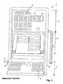
- the FIG. 1 shows a control unit 1 of the prior art, as manufactured by the applicant.
- the uppermost sector shows a top control panel 2 with a large number of mechanical buttons 3, each of which is provided according to their function with a dedicated symbol for surgical procedures.
- the middle sector is a screen 4 with a status display for individual components of the machine and for the actual states with respect to the process parameters. On the screen 4 any representations, schemes and processes can be called up and displayed. The call is made by means of corresponding keys of the bottom control panel or the keyboard 5.
- the lowest sector of the FIG. 1 shows the control panel 5 for entering the parameter values with classic mechanical buttons.
- the keyboard 5 is on a horizontal axis 7 up and folded down (arrow 8). This allows analogous to a typewriter keyboard with the fingers to operate the individual input buttons 6.
- the entire operating unit is designed according to the ergonomic aspects and as a whole by means of a handle 9 in height adjustable.
- the screen 4 is about to be able to be set to eye level according to the size of the respective operator and the control panel 5 with the mechanical buttons on comfortable position and height for manual inputs.
- the WO01 / 969 shows a further solution of the prior art for a control unit to an injection molding machine.
- This shows a touch screen, around which mechanical keys are arranged, which are divided into the regions A - E.
- the icons are shown at the edge of the screen.
- This solution is suitable in connection with the situational change of presentation. This operation is an improvement over the previously described solutions because fewer keys are needed. In the solution, however, it is always come back when operating that you mistakenly press the icon on the screen instead of pressing the button next to it. The actual operation takes place on the touch screen. Below the screen are two rows of mechanical buttons.
- the operating device comprises an actuating element with a guide for the actuating operation, to which a plurality of operating tasks can be assigned by means of the user interface, so that as a result of the guided actuation of the actuating element, a respectively assigned operating operation can be carried out.
- the joystick has a guide for the operation.
- This can for example be a guide for the movement right / left and / or for the movement up / down.
- Guide means therefore no one-dimensional forced movement, but that at least one preferred direction for the operator is noticeable upon actuation of the actuating element.
- the actuator not only assigned to a single operation, but a plurality of operating activities is assigned. It is therefore a universal control element. This distinguishes the invention of solutions in which individual operating activities are each associated with a corresponding operating device (switch, turntable or the like). It is a variety of individual controls and the associated confusion avoided.
- the WO01 / 67191 shows a device for operating, monitoring and / or monitoring a manufacturing device such as an injection molding machine with first means for storing input and / or display pages in a tree structure. It is provided, with a first control element for calling a page of a first hierarchical level and for calling at least one subordinate page of a second hierarchical level, with second means for storing a traversed in the tree by calling pages path and further with a second control for stepping back the path.
- a preferred form of the actuator is a rotary actuator.
- the rotation of the rotary actuator by the operator in a clockwise or counterclockwise direction represents a one-dimensional movement and therefore leaves no areal freedom of movement.
- the actuator is only one-dimensionally movable. This can be achieved for example in a rotary control element by spatial definition of the axis of rotation. Therefore, the actuator may for example be a spherical element with a fixed axis of rotation.
- the disadvantage is that the user interface must be re-designed for each machine type again.
- the inventive control device is characterized by the features of claim 1.
- the programming control panel is the sequence programming for the functions of all components of the machine or device performed and used on the operating panel to reduce the number of entries a part of the input points due to appropriate programming and displays at the input points multiple times.
- the operator does not feel during the sequence programming and parameterization that in the background with respect to the individual components necessary for surgical intervention input points are prepared for their function, so that on the operating panel for the parameterization of the individual components and / or for each operatively to influencing components required input points are automatically activated when calling a component on the screen.
- the operator be it for setting up a tool or for surgical procedures, e.g.
- a part of the inputs with view of the screen by means of input points in the area of the programming control panel and another part of the inputs, in particular the operational inputs, with a view of the machine by means of visible and palpable touch screen locations in the operational control panel made. It is advantageous, however, if also the part of the inputs is made with a view of the screen by means of touchscreen input points.
- a touch screen has the greater advantage that on the screen itself at the marked points inputs can be made, which are directly for the function shown.
- the new solution allows the touchscreen to be used in the opposite direction by displaying the function in question at the entry point.
- the touchscreen locations in the area of the operative control panel are now not only visible but by appropriate profiling, e.g. by projecting Um chargedsr instruments, also made tangible, this facilitates the rapid learning of the operation.
- the operator can confirm with a glance that he has his finger on the correct entry point. Later he will master the operation according to the dummy writing on the typewriter. If the display panels have 50 to 100 input points as in the prior art, "blind" operation is excluded.
- a particularly advantageous application for the new invention relates to injection molding machines, which is part of a production cell for the cyclical production of molded parts and the operator of the production process on the screen in the field of programming control panel is configured or recorded.
- the operator configures or imports the production process by means of a storing data processing unit on the operating unit via touchscreen inputs in the area of the programming control panel.
- the operating parameters are entered and changed from the operating panel in a prepared mask of the programming panel.
- the machine control has event interfaces and provides control commands or control commands, eg for individual components, in the form of a command interface to disposal.
- control commands or control commands eg for individual components
- the configuration of the production process is performed via touchscreen input points with regard to the screen in the area of the programming control panel and the parameterization as well as the input of control commands or control commands for the real movement of the components of the production cell via the visible and perceptible touchscreen locations in the area of the operative control panel.
- operational inputs and control commands take place in the area of the operating control panel. Corrections to operating parameters are displayed in the programming panel and are input to the memory.
- Physical parameters or parameters eg speed (V), pressure (P), force (F) and travel (S), are parameterized in the operating panel via "+" (plus) touchscreen locations or "-" (minus) touchscreen locations entered and increased or decreased.
- the operating unit is assigned a software for selecting or selecting individual component schemes on the programming panel, with the selection of schemes automatically only necessary visible and palpable touchscreen keys of the operating panel are activated, so made using the activated keys component-specific inputs can be.
- At least part of the touch screen locations in the area of the operative control panel can be independent touchscreen sectors, such that two or more of the touchscreen locations in question can be operated simultaneously.
- Keys are normally understood to mean mechanical keys, which are usually engaged by pressing with a finger. In the case of electrical equipment a switching function is triggered accordingly.
- a switching function is triggered accordingly.
- the screen control panel is understood to be the front surface of a control box, which is usually placed close to the main interventions on the machine itself and is used for direct operation.
- the control cabinet which has much larger dimensions, is usually placed next to the machine, often on a wall.
- the new solution only a limited number of visible and palpable touchscreen locations or keys are physically specified.
- program-assisted symbol representations on the touch screen locations or keys and corresponding function connections the same touch screen locations or keys can be used in different ways for controlling other components and function connections.
- the operational panel has a limited, relatively small number of input locations. Part of the input points of the operating panel is made due to appropriate programming for different functions or reusable. The currently activated function is automatically displayed at the input points of the operating panel.
- the touchscreen input points in the programming control panel coordinate-related and the touchscreen input points of the operating panel are programmed sector-related.
- the input points are image-related and must be programmed to match the image coordinate-related. The situation is different for the operative control panel.
- the touch screen function has a software via which automatically activatable visible and palpable touchscreen input points with the corresponding symbols can be displayed and illuminated.
- tactile feedback is associated with the touchscreen input locations for sensory confirmation that a control command is actually being input or accepted, with the tactile feedback being individual Buttons, individual panels or an entire input unit can be assigned.
- the touchscreen panels can be arranged within a screen surface and the visible and palpable touchscreen input points can be formed by attaching a profile-forming mask.
- a mask can extend over the entire screen surface, wherein at least a part of the touch screen field for the visible touch screen input points can be designed as uncovered windows or as a transparent layer.
- the mask extends only over the operative control panel and in the region of the individual keys has openings which are formed by punching and / or by a transparent film.
- the opening area around the touch surface may have embossed features such as edges or protrusions.
- the programming control panel and the operational control panel are mounted on separate screens.
- the touchscreen input points of the operative control panel are particularly advantageously arranged on at least two or more screens or one screen per touchscreen input location. This allows, as stated earlier, to make the screen layout so that the touch screen input points of the operating panel are programmed sector-related.
- the controller recognizes which input location has been actuated so that the command is processed correctly.
- the operating unit has an additional box, in particular for read-in points and / or safety switches and / or for other interfaces, such as a touchpad on a laptop and / or another electronic control unit with remote control and / or an emergency / off button ,
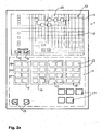
- the programming panel 10 is shown, which is enclosed by a dash-dotted line. Directly below is the operative panel 11, which is framed by a dashed line.
- the programming control panel is used for visual visualization, eg of all process and machine-relevant data, flowcharts and current process states.
- An important part of the programming control panel 10 is the programming of the injection molding process.
- the screen 12 of the programming control panel 10 has a sensitive surface, which allows coordinates to program the input sites and to enter directly on the touchscreen screen. Symbolically, the sensitive surface is marked with thin lines.
- the second operational control panel 11 has different input locations.
- Selector switch 14 is the classic touch screen function for activating buttons on the programming panel 10.
- selector switch 13 a mouse pad function can be substituted for the classic mouse function. The desired entry point is made by moving your finger on the screen.
- An alternative switch automatically occurs with the switching of the application, e.g. by means of operating manual with mouse operation.
- the programming can be done at the machine manufacturer. During sequence programming, these input points are activated only in case of need.
- the entry points 19, 20, 21 are locked for other functions.
- All other input locations 22 are defined by the programming or configuration on the programming panel on a case-by-case basis for their function. It is possible that only the visualized in the flowchart display 36 components are occupied or defined in the input locations 22. It can be one, two or more components or in very simple cases even all components. It is further proposed that at least the blocks 15 and 16 and possibly 17 be occupied by the machine manufacturer via a corresponding programming. The block 18 and possibly 17 can be reserved as a reserve eg for the user. There are also other interventions, which are almost invariably needed in injection molding machines. These entry points 23 are fixed.
- the operating panel contains the button on the screen so that graphical symbols or small films or sequence sequences and states such as on / off can be displayed on the individual keys.
- mouse guide can be used as an example, the keypad 19 is fixed for the movement of the form, but depending on the mode change the function: Hand: Open / close form ATM: +/-, so that, for example, the molding speed can be adjusted
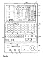
- FIG. 2b shows a further embodiment of FIG. 2a
- a numeric input field 25 On the programming control panel 10 is a numeric input field 25.
- the numeric input field is displayed as a window on the screen, primarily for the parameterization of the individual components.
- six further input points 26, 27, 28 are shown in the activated state. These input points are considered as examples of an inventive definition of the input points, this on the basis of working in the background programs and appropriate activation by the component selection in the configuration on the programming panel 10.
- the operational control panel 11 further fixed keys 29, which also concern basic functions such as cooling water, heaters, hydraulic systems, power supply, etc.
- the numerical input field 25 is used to enter the desired value for each variable process factor.
- a keyboard for text texts can be provided on the programming panel.
- all input points in the operative control panel can be designed as touchscreen input points.
- the input points which are automatically programmable for the current use in a multiple use, or which can be changed automatically by the controller of the programming panel.
- auxiliary box 30 on which there is an emergency on / off switch 31, an additional mousepad 32 and a slot 33 for inserting a card for operator identification.
- Key location 34 is a mode lock switch. 34 'and 34 "are other key switches.
- Each use has its own parameterization.
- synchronizations 42a, 42b can be inserted between the commands and optionally also parameterized. It is also possible to move or delete the commands and synchronizations inserted in the process or to change the associated parameterization.
- many commands are symmetric, i. if an axle (for example, an ejector) is driven up, it must at some point also be driven back.
- the existing procedure is inserted as a macro in a further sequence like a command.
- the macro can be expanded on the screen 12, for example to adjust the parameterization.
- the creation of a process on the basis of the existing components and their commands is not limited. However, the user is informed of potential errors in the process as part of a plausibility check. If, for example, the ejector is to approach with the tool closed, this must be confirmed by the user.
- the parameterization field 37 indicates, with the input location 41, how many stages are involved in the example of the mold opening.
- the parameterization is displayed at the entry points 43 to 46, with the entry points 43, 46 indicating the speed in% of a maximum speed.
- the entry points 44 and 45 indicate the way.
- the numerical values can be changed eg via the numeric keypad or an input position +/- of the operative control panel ( FIG. 2 ).
- FIGS. 4 and 5 show two examples of the specific design of the programming panel and the operating panel 10 and 11.
- the FIG. 4 shows a solution with a screen 50, on the whole surface of a touch foil is attached.
- a mask 51 with an upper, large cutout 52 is shown in exploded view over the screen.
- the cutout 52 is the programming panel.
- the lower half of the mask 51 has individual cutouts 53.
- the touchscreen must be coordinate-programmable over the whole area, so that an error-free assignment of the input locations exists in the programming control panel as well as in the operative control panel.
- the mask may be formed, for example, as a thin metal or plastic plate or embossed film. This creates a noticeable edge through the cutouts 52 and the underlying touch foil. This edge also allows a "blind" feel of the input location, in the sense of a typewriter keyboard.
- the keys 53 can not be operated simultaneously.
- the operative control panel is formed with individual keys as input location.
- the operational control panel can be programmed sectorally.
- Each input point 53 is formed with a correspondingly sensitive coating and corresponding data connection with the programming control panel for a data exchange in both directions.
- the upper part is a per se known touchscreen 54; the entire lower screen 55 is formed only in sectors in the area of the input location as a single keyboard.
- two or more keys 53 may be operated simultaneously.
- FIGS. 6a to 6c schematically show various possibilities of arrangement of the programming control panel and the operative control panel on a screen ( Figures 6a and 6b ) and on two independent screens ( FIG. 6c ).
- FIG. 7 schematically shows an example of a whole controller, eg for an injection molding machine or die casting machine.
- the operating unit 60 On the left in the picture is the operating unit 60.
- the electrical components On the right in the picture are the electrical components, which are accommodated in a control cabinet 61.
- Head of the controller is an industrial PC (IPC) 62, which is directly connected to the screen 63 and a USB interface. If more than one input location needs to be actuated simultaneously in special applications on the operational control panel 11, an additional data connection 64 is provided by the operational control panel 11.
- IPC industrial PC
- FIGS. 8 and 9 show a scheme for a whole control system for an injection molding machine.
- the system model underlying the control FIGS. 8 and 9 considers the machine as a composite of cooperating components.
- a component 74a, 74b, 74x or 77a-x embodies any element of the injection molding machine, both logical and physical, including peripherals possibly associated therewith.
- the user creates machine sequences on the operating unit 72 or on the operator terminal 71. To execute a machine run, it is loaded from the controller into the process engine.
- the process engine 73 now drives the process, that is, it calls on the involved components 74 the commands 75 according to the loaded machine sequence.
- a component has executed a command, this is signaled to the caller of the command 76.
- the process engine 73 calls on the components of the commands according to the production process. For example, the process engine calls the command “Close” on the component “Form” 74a. The mold component in turn calls on the electric linear axis "positive locking” 77a the command "driving". Via the basic library 78, the travel job is sent to the controller 79 or 90 (FIG. FIG. 9 ), which regulates the movement of the axle according to the given driving profile. When the axis has reached its destination, this is indicated by the controller of the linear axis component 77a.
- Logical components 74 represent a functional unit of the injection molding machine or the production cell, for example the form-fitting unit (short form) 74a, the metering and injection unit (short screw) 74b etc.
- a logical component can consist of several axes.
- the metering and injection unit 74b consists of a linear 77b and a rotation axis 74c.
- a technical component 77 represents an axis. It ensures that the drive technology can be easily exchanged by encapsulating the drive technology. This means that changing the drive technology has no influence on the logical components or on the configured machine sequences.
- the physically real components are down in FIG. 8 symbolically represented with the image of an injection molding machine 100.
- drive or axis forming movement 101, ejector 102, movable mold or tool 103, screw 104, linear drive of the worm (linear axis) 105 and rotation drive of the worm (rotation axis) 106 , Aggregate 107, protective hood 108th
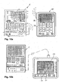
- FIG. 10a the stationary control unit is associated with a mobile hand control unit 95, which is advantageously on the radio with the stationary control unit in the data exchange for both directions.
- the mobile hand control device has a small screen 96.
- Both panels 96, 97 of the manual control unit 95 are designed analogously to the stationary user interface of the control unit 1.
- programming the process flow would not be convenient because the user interface would be too small.
- the user interface is large enough for surgical interventions on the machine.
- the advantage of the manual control unit is that it can be brought close to the place where influence has to be taken. Primarily these are motion commands. Accordingly simplifies the control panel can be designed with the hand control unit.
- the two control units can currently be mutually locked so that incorrect entries are avoided.
- control panel 1 Everything that is on the screen (control panel 1) can be made on the screen, so even at a distance.
- control panel 2 with respect to the key design. This can be designed in any size, shape and style.
- individual fields for operation can be enlarged in terms of the Windows concept.
Landscapes
- Engineering & Computer Science (AREA)
- Human Computer Interaction (AREA)
- Manufacturing & Machinery (AREA)
- Physics & Mathematics (AREA)
- General Physics & Mathematics (AREA)
- Automation & Control Theory (AREA)
- User Interface Of Digital Computer (AREA)
- Injection Moulding Of Plastics Or The Like (AREA)
Claims (17)
- Dispositif de pilotage pour piloter une ou plusieurs machine(s) ou une cellule de production avec des séquences pouvant être répétées de manière cyclique- comprenant un pilotage de machine ainsi- qu'une unité de commande (1), conçue en tant qu'Interface-Homme-Machine (MMI), dans lequel-- les séquences de machine et les paramètres de production sur l'unité de commande peuvent être saisis et modifiés sur des emplacements de saisie par l'humain, respectivement l'utilisateur à l'aide d'un écran,-- l'unité de commande présente au moins un panneau de commande de programmation (10) pour la programmation des séquences et un panneau de commande opérationnel (11) pour la saisie en visualisant la machine de production,
caractérisé en ce que-- dans le panneau de commande opérationnel (11), des emplacements de saisie d'écran tactile (19, 20, 21, 22) visibles et tactiles sont prévus qui sont formés en appliquant un masque (51) formant un profil sur un écran tactile,-- au moins une partie des emplacements de saisie d'écran tactile (19, 20, 21, 22) du panneau de commande opérationnel (11) peuvent être programmés pour leur fonction selon les saisies du panneau de commande de programmation (101),-- et le panneau de commande de programmation (101) et le panneau de commande opérationnel (11) sont conçus pour un échange de données programmé dans les deux sens. - Dispositif de commande selon la revendication 1,
caractérisé en ce
que le panneau de commande opérationnel (11) présente des espaces de saisie par écran tactile visibles et sensibles au toucher par des attributs gravés. - Dispositif de commande selon la revendication 1 ou 2,
caractérisé en ce
que le panneau de commande de programmation (10) présente des espaces de saisie par écran tactile pour la programmation des opérations et le panneau de commande opérationnel (11) présente des espaces de saisie par écran tactile pour les interventions opérationnelles, sachant que le panneau de commande de programmation (10) et le panneau de commande opérationnel (11) sont conçus pour un échange de données programmé dans les deux sens. - Dispositif de commande selon l'une des revendications 1 à 3,
caractérisé en ce
que le panneau de commande opérationnel (11) présente un nombre limité d'espaces de saisie par écran tactile et une partie des espaces de saisie par écran tactile du panneau de commande opérationnel (11) peuvent être utilisés pour diverses fonctions ou plusieurs fois du fait de la programmation correspondante, sachant que la fonction activée peut être affichée automatiquement sur les espaces de saisie par écran tactile du panneau de commande opérationnel (11) . - Dispositif de commande selon l'une des revendications 1 à 4,
caractérisé en ce
que la machine est une machine de moulage par injection (100) ou une machine de moulage sous pression. - Dispositif de commande selon l'une des revendications 1 à 5,
caractérisé en ce
que les espaces de saisie par écran tactile dans le panneau de commande de programmation (10) peuvent être programmés par rapport aux coordonnées et les espaces de saisie par écran tactile (19, 20, 21, 22) du panneau de commande opérationnel (11) peuvent être programmés par rapport aux secteurs. - Dispositif de commande selon l'une des revendications 1 à 6,
caractérisé en ce
qu'un masque formant profilés (51) peut être visualisé sur l'écran du panneau de commande de programmation (10), de telle sorte que l'opération et le paramétrage peuvent être configurés et paramétrés sur l'interface utilisateur du panneau de commande de programmation (10), sachant que le masque formant profilés (51) présente un panneau visualisant les opérations (36), une liste de composantes des composantes de la machine pouvant être commandées avec des commandes pouvant être sélectionnées, et un panneau de paramétrage (37) en plus. - Dispositif de commande selon l'une des revendications 1 à 7,
caractérisé en ce
que les espaces de saisie par écran tactile visibles et sensibles au toucher respectivement nécessaires, peuvent être activés en sélectionnant les schémas de composantes ou les paramètres affichés à l'écran automatiquement avec les liaisons fonctionnelles nécessaires correspondantes pour les espaces de saisie par écran tactile (19, 20, 21, 22) visibles et sensibles au toucher. - Dispositif de commande selon l'une des revendications 1 à 8,
caractérisé en ce
qu'une commande est prévue pour la fonction écran tactile, par le biais de laquelle les espaces de saisie par écran tactile (19, 20, 21, 22) visibles et sensibles au toucher pouvant être activés, peuvent être affichés et éclairés avec les symboles correspondants. - Dispositif de commande selon l'une des revendications 1 à 9,
caractérisé en ce
que les espaces de saisie par écran tactile (19, 20, 21, 22) visibles et sensibles au toucher présentent au moins une fonction triple :- un affichage lumineux en tant qu'affichage du statut,- l'affichage d'un symbole en rapport avec la fonction à déclencher par les touches, respectivement, la signification de la fonction tactile,- en tant que saisie de commande et instruction de commande pour une activation d'opérations de la machine et/ou une modification de paramètres de production. - Dispositif de commande selon l'une des revendications 1 à 10,
caractérisé en ce
qu'un retour tactile est attribué aux espaces de saisie par écran tactile (19, 20, 21, 22) pour la confirmation sensorielle que l'instruction de commande est donnée, respectivement acceptée effectivement, sachant que le retour tactile est attribué à différentes touches ou différents panneaux de commande d'écran ou à une unité de saisie complète. - Dispositif de commande selon l'une des revendications 1 à 11,
caractérisé en ce
que des panneaux d'écran tactile sont disposés à l'intérieur d'une surface d'écran, lesquels sont formés par l'application d'un masque formant profilés (51). - Dispositif de commande selon la revendication 12,
caractérisé en ce
que le masque formant profilés (51) s'étend sur toute la surface d'écran, sachant qu'au moins une partie du panneau d'écran tactile pour les espaces de saisie par écran tactile (19, 20, 21, 22) visibles est conçue en tant que fenêtre non masquée ou couche transparente. - Dispositif de commande selon la revendication 12 ou 13,
caractérisé en ce
que le masque formant profilés (51) s'étend uniquement sur le panneau de commande opérationnel (11) et présente des ouvertures au niveau des différents espaces de saisie, qui sont formées par matriçage et/ou par un film transparent et la zone d'ouverture autour d'une surface tactile présente des attributs gravés, comme des bords ou des bossages. - Dispositif de commande selon l'une des revendications 1 à 14,
caractérisé en ce
que les fonctions ou du moins des fonctions partielles du panneau de commande opérationnel (11) sont dupliquées dans un appareil de commande manuel mobile (95) correspondant. - Dispositif de commande selon la revendication 15,
caractérisé en ce
que le panneau de commande opérationnel (11) est disposé de façon stationnaire et l'appareil de commande manuel mobile (95) peut être verrouillé en plus pour l'utilisation et/ou que le panneau de commande opérationnel (11) stationnaire peut être verrouillé en cas d'utilisation via l'appareil de commande manuel mobile (95). - Dispositif de commande selon la revendication 15 ou 16,
caractérisé en ce
que l'appareil de commande manuel mobile (95) est par exemple un téléphone portable avec écran, un PDA, un Smartphone ou un ordinateur portable (95) et l'échange de données est filaire (99) ou a lieu sans fil ou par radio ou IR ou IrDA ou Bluetooth, ou bien Wireless USB ou WLAN.
Applications Claiming Priority (4)
| Application Number | Priority Date | Filing Date | Title |
|---|---|---|---|
| CH11882005 | 2005-07-18 | ||
| CH14722005 | 2005-09-10 | ||
| CH6292006 | 2006-04-15 | ||
| PCT/CH2006/000349 WO2007025396A1 (fr) | 2005-07-18 | 2006-06-30 | Procede et dispositif de commande permettant de commander une ou plusieurs machines |
Publications (3)
| Publication Number | Publication Date |
|---|---|
| EP1907906A1 EP1907906A1 (fr) | 2008-04-09 |
| EP1907906B1 EP1907906B1 (fr) | 2015-03-18 |
| EP1907906B2 true EP1907906B2 (fr) | 2018-10-10 |
Family
ID=36999840
Family Applications (1)
| Application Number | Title | Priority Date | Filing Date |
|---|---|---|---|
| EP06741674.3A Not-in-force EP1907906B2 (fr) | 2005-07-18 | 2006-06-30 | Procede et dispositif de commande permettant de commander une ou plusieurs machines |
Country Status (2)
| Country | Link |
|---|---|
| EP (1) | EP1907906B2 (fr) |
| WO (1) | WO2007025396A1 (fr) |
Families Citing this family (24)
| Publication number | Priority date | Publication date | Assignee | Title |
|---|---|---|---|---|
| EP1907906B2 (fr) * | 2005-07-18 | 2018-10-10 | Netstal-Maschinen AG | Procede et dispositif de commande permettant de commander une ou plusieurs machines |
| CH702036B1 (de) * | 2006-12-13 | 2011-04-29 | Netstal Ag Maschf Giesserei | Verfahren zur Steuerung einer Maschine sowie Steuervorrichtung. |
| DE102007050073B4 (de) | 2007-10-19 | 2009-10-08 | Kraussmaffei Technologies Gmbh | Steuervorrichtung einer Kunststoff verarbeitenden Maschine |
| CH703401B1 (de) | 2010-07-02 | 2019-04-30 | Ferag Ag | Verfahren und Vorrichtung zum Erzeugen einer Benutzerschnittstelle zum Bedienen von Maschinen. |
| CH704778B1 (de) | 2011-04-18 | 2017-01-13 | Ferag Ag | Grafische Benutzerschnittstelle. |
| CH703723A1 (de) | 2010-09-15 | 2012-03-15 | Ferag Ag | Verfahren zur konfiguration einer grafischen benutzerschnittstelle. |
| CH703724A1 (de) | 2010-09-15 | 2012-03-15 | Ferag Ag | Grafische benutzerschnittstelle. |
| US9317193B2 (en) | 2010-09-15 | 2016-04-19 | Ferag Ag | Graphical user interface |
| AT12347U1 (de) * | 2010-10-18 | 2012-04-15 | Engel Austria Gmbh | Berührungsempfindlicher bildschirm mit verschiebbaren tasten |
| CH703962A1 (de) | 2010-10-22 | 2012-04-30 | Ferag Ag | Produktweiterverarbeitungsanlage. |
| DE102010051639A1 (de) | 2010-11-17 | 2012-05-24 | Netstal-Maschinen Ag | Steuerungsvorrichtung mit Multi-Touch Funktionalität |
| WO2012073368A1 (fr) * | 2010-12-02 | 2012-06-07 | 三菱電機株式会社 | Dispositif de commande de valeurs numériques |
| AT12570U1 (de) * | 2011-02-03 | 2012-08-15 | Engel Austria Gmbh | Bedieneinheit für eine spritzgiessmaschine |
| AT511487B1 (de) | 2011-06-09 | 2016-01-15 | Engel Austria Gmbh | Bedieneinheit für eine spritzgiessmaschine |
| DE102012013773A1 (de) * | 2012-07-11 | 2014-01-16 | Wittmann Battenfeld Gmbh | Kunststoffverarbeitungsmaschine, System bestehend aus mindestens zwei Kunststoffverarbeitungsmaschinen und Verfahren zum Betreiben eines solchen Systems |
| AT513666B1 (de) * | 2012-11-26 | 2018-12-15 | Engel Austria Gmbh | Bedieneinheit für eine Spritzgießmaschine |
| DE102013219036A1 (de) * | 2013-09-23 | 2015-03-26 | Robert Bosch Gmbh | Maschine, sicherungssystem für mobile anzeigeeinrichtung und verfahren zum sichern der mobilen anzeigeeinrichtung |
| DE102013220865A1 (de) * | 2013-10-15 | 2015-04-16 | Trumpf Werkzeugmaschinen Gmbh + Co. Kg | Verfahren und System zum Fernbedienen einer Werkzeugmaschine mittels eines mobilen Kommunikationsgeräts |
| DE202015103287U1 (de) | 2015-06-23 | 2015-08-14 | Netstal-Maschinen Ag | Steuervorrichtung mit integrierbarer SPS |
| AT517785A1 (de) * | 2015-09-30 | 2017-04-15 | Engel Austria Gmbh | Steuervorrichtung für eine Formgebungsmaschine |
| DE102016107583A1 (de) * | 2016-04-25 | 2017-10-26 | Keba Ag | Bedienpanel zum Steuern einer industriellen Anlage |
| DE102016119853A1 (de) | 2016-10-18 | 2018-04-19 | Arburg Gmbh + Co Kg | Interaktives Steuern einer Maschine mit Rückmeldung eines Stellparameters |
| JP7042674B2 (ja) * | 2018-03-29 | 2022-03-28 | 住友重機械工業株式会社 | 射出成形機の操作用表示装置および、射出成形機 |
| CH715651B1 (de) * | 2019-02-26 | 2020-06-15 | Reishauer Ag | Bedientafel für eine Werkzeugmaschine. |
Citations (3)
| Publication number | Priority date | Publication date | Assignee | Title |
|---|---|---|---|---|
| DE20007972U1 (de) † | 2000-02-11 | 2000-10-26 | Ascom Ag Bern | Berührungsempfindlicher Bildschirm |
| US6437774B1 (en) † | 1996-03-26 | 2002-08-20 | Idec Izumi Corporation | Display and input device and display and input system |
| WO2005009719A1 (fr) † | 2003-07-26 | 2005-02-03 | Karl Hehl | Procede et dispositif de commande interactive d'une machine |
Family Cites Families (8)
| Publication number | Priority date | Publication date | Assignee | Title |
|---|---|---|---|---|
| DE68925271T2 (de) * | 1988-10-27 | 1996-08-14 | Texas Instruments Inc | Kommunikations-, Informations-, Wartungsdiagnostik und Ausbildungssystem |
| DE4219259A1 (de) | 1992-06-12 | 1993-12-16 | Karl Hehl | Verfahren zur Steuerung einer Kunststoff-Spritzgießmaschine |
| WO2001067191A2 (fr) | 2000-03-06 | 2001-09-13 | Siemens Aktiengesellschaft | Procede et dispositif pour faire actionner, observer et/ou surveiller un systeme de fabrication |
| US6684264B1 (en) | 2000-06-16 | 2004-01-27 | Husky Injection Molding Systems, Ltd. | Method of simplifying machine operation |
| US20040090428A1 (en) * | 2002-11-08 | 2004-05-13 | Xerox Corporation | Overlays with raised portions for touch-sensitive screens |
| AU2003267029A1 (en) | 2003-08-30 | 2005-04-14 | Hauni Maschinenbau Ag | Operating unit for a machine in the tobacco-processing industry |
| US7986306B2 (en) * | 2003-11-18 | 2011-07-26 | Johnson Controls Technology Company | Reconfigurable user interface |
| EP1907906B2 (fr) * | 2005-07-18 | 2018-10-10 | Netstal-Maschinen AG | Procede et dispositif de commande permettant de commander une ou plusieurs machines |
-
2006
- 2006-06-30 EP EP06741674.3A patent/EP1907906B2/fr not_active Not-in-force
- 2006-06-30 WO PCT/CH2006/000349 patent/WO2007025396A1/fr not_active Ceased
Patent Citations (3)
| Publication number | Priority date | Publication date | Assignee | Title |
|---|---|---|---|---|
| US6437774B1 (en) † | 1996-03-26 | 2002-08-20 | Idec Izumi Corporation | Display and input device and display and input system |
| DE20007972U1 (de) † | 2000-02-11 | 2000-10-26 | Ascom Ag Bern | Berührungsempfindlicher Bildschirm |
| WO2005009719A1 (fr) † | 2003-07-26 | 2005-02-03 | Karl Hehl | Procede et dispositif de commande interactive d'une machine |
Non-Patent Citations (1)
| Title |
|---|
| Betriebsanleitung für Maschinennummer 193077 der Arburg GmbH+Co KG, 08 März 2004, Seiten 113-195 † |
Also Published As
| Publication number | Publication date |
|---|---|
| EP1907906A1 (fr) | 2008-04-09 |
| EP1907906B1 (fr) | 2015-03-18 |
| WO2007025396A1 (fr) | 2007-03-08 |
Similar Documents
| Publication | Publication Date | Title |
|---|---|---|
| EP1907906B1 (fr) | Procede et dispositif de commande permettant de commander une ou plusieurs machines | |
| EP2100197B1 (fr) | Unité de commande à touches d'écran tactile | |
| DE60113685T2 (de) | Schnittstelle zur maschinensteuerung | |
| EP2227368B1 (fr) | Procédé de commande interactive d'une machine | |
| EP2828056B1 (fr) | Dispositif et procédé destinés à commander une machine de moulage par injection équipée d'un appareil de manipulation | |
| DE112011102645B4 (de) | Steuerungsvorrichtung für eine Formmaschine und Herstellungsverfahren für geformte Artikel | |
| WO2005009719A1 (fr) | Procede et dispositif de commande interactive d'une machine | |
| EP1902827B1 (fr) | Commande pour une machine de formage par soufflage dotée de plusieurs unités fonctionnelles | |
| DE102007050073B4 (de) | Steuervorrichtung einer Kunststoff verarbeitenden Maschine | |
| DE102017004926A1 (de) | Numerische Steuerung | |
| EP2735425B1 (fr) | Unité de commande pour une machine de moulage par injection | |
| EP0378649A1 (fr) | Dispositif pour introduire des donnees de commande dans une machine-outil cnc. | |
| DE102019117093A1 (de) | Produktionsmaschine mit steuerungsprogramm | |
| DE102011016712A1 (de) | Berührungsempfindlicher Bildschirm | |
| WO2017186369A1 (fr) | Panneau de commande d'une installation industrielle | |
| EP2613239B1 (fr) | Installation mobile pour l'émission et la réception de données assistées par ordinateur avec une unité d'émission à l'écran intégrée et procédé de visualisation de sa commande | |
| WO2012066020A2 (fr) | Dispositif de commande avec fonctionnalité tactile multipoint | |
| DE102017006702A1 (de) | Numerische Steuerung mit Handradvorschubfunktion | |
| DE102009037165A1 (de) | Vorrichtung zur Steuerung einer Werkzeugmaschine | |
| EP2735424A1 (fr) | Unité de commande pour une machine de moulage par injection | |
| EP3542235B1 (fr) | Commande interactive d'une machine dotée d'un retour d'information sur un paramètre de réglage | |
| EP3268852B1 (fr) | Procédé de sélection ciblée d'éléments affichés sur un écran tactile | |
| EP0851448B1 (fr) | Unité de commande configurable pour commander des dispositifs électroniques | |
| EP2735929A1 (fr) | Unité d'affichage et de commande pour une machine de moulage à injection | |
| DE10207534A1 (de) | Anzeigeverfahren zur Unterstützung der Ein- und Ausgabe von Daten in Tabellenkalkulationsprogrammen |
Legal Events
| Date | Code | Title | Description |
|---|---|---|---|
| PUAI | Public reference made under article 153(3) epc to a published international application that has entered the european phase |
Free format text: ORIGINAL CODE: 0009012 |
|
| 17P | Request for examination filed |
Effective date: 20080218 |
|
| AK | Designated contracting states |
Kind code of ref document: A1 Designated state(s): AT BE BG CH CY CZ DE DK EE ES FI FR GB GR HU IE IS IT LI LT LU LV MC NL PL PT RO SE SI SK TR |
|
| 17Q | First examination report despatched |
Effective date: 20100907 |
|
| DAX | Request for extension of the european patent (deleted) | ||
| GRAP | Despatch of communication of intention to grant a patent |
Free format text: ORIGINAL CODE: EPIDOSNIGR1 |
|
| INTG | Intention to grant announced |
Effective date: 20141022 |
|
| GRAS | Grant fee paid |
Free format text: ORIGINAL CODE: EPIDOSNIGR3 |
|
| GRAA | (expected) grant |
Free format text: ORIGINAL CODE: 0009210 |
|
| AK | Designated contracting states |
Kind code of ref document: B1 Designated state(s): AT BE BG CH CY CZ DE DK EE ES FI FR GB GR HU IE IS IT LI LT LU LV MC NL PL PT RO SE SI SK TR |
|
| REG | Reference to a national code |
Ref country code: GB Ref legal event code: FG4D Free format text: NOT ENGLISH |
|
| REG | Reference to a national code |
Ref country code: CH Ref legal event code: EP |
|
| REG | Reference to a national code |
Ref country code: IE Ref legal event code: FG4D Free format text: LANGUAGE OF EP DOCUMENT: GERMAN |
|
| REG | Reference to a national code |
Ref country code: AT Ref legal event code: REF Ref document number: 716954 Country of ref document: AT Kind code of ref document: T Effective date: 20150415 |
|
| REG | Reference to a national code |
Ref country code: DE Ref legal event code: R096 Ref document number: 502006014248 Country of ref document: DE Effective date: 20150430 |
|
| REG | Reference to a national code |
Ref country code: NL Ref legal event code: T3 |
|
| PG25 | Lapsed in a contracting state [announced via postgrant information from national office to epo] |
Ref country code: FI Free format text: LAPSE BECAUSE OF FAILURE TO SUBMIT A TRANSLATION OF THE DESCRIPTION OR TO PAY THE FEE WITHIN THE PRESCRIBED TIME-LIMIT Effective date: 20150318 Ref country code: LT Free format text: LAPSE BECAUSE OF FAILURE TO SUBMIT A TRANSLATION OF THE DESCRIPTION OR TO PAY THE FEE WITHIN THE PRESCRIBED TIME-LIMIT Effective date: 20150318 Ref country code: SE Free format text: LAPSE BECAUSE OF FAILURE TO SUBMIT A TRANSLATION OF THE DESCRIPTION OR TO PAY THE FEE WITHIN THE PRESCRIBED TIME-LIMIT Effective date: 20150318 |
|
| PGFP | Annual fee paid to national office [announced via postgrant information from national office to epo] |
Ref country code: CH Payment date: 20150604 Year of fee payment: 10 |
|
| REG | Reference to a national code |
Ref country code: LT Ref legal event code: MG4D |
|
| PG25 | Lapsed in a contracting state [announced via postgrant information from national office to epo] |
Ref country code: GR Free format text: LAPSE BECAUSE OF FAILURE TO SUBMIT A TRANSLATION OF THE DESCRIPTION OR TO PAY THE FEE WITHIN THE PRESCRIBED TIME-LIMIT Effective date: 20150619 Ref country code: LV Free format text: LAPSE BECAUSE OF FAILURE TO SUBMIT A TRANSLATION OF THE DESCRIPTION OR TO PAY THE FEE WITHIN THE PRESCRIBED TIME-LIMIT Effective date: 20150318 |
|
| PG25 | Lapsed in a contracting state [announced via postgrant information from national office to epo] |
Ref country code: EE Free format text: LAPSE BECAUSE OF FAILURE TO SUBMIT A TRANSLATION OF THE DESCRIPTION OR TO PAY THE FEE WITHIN THE PRESCRIBED TIME-LIMIT Effective date: 20150318 Ref country code: PT Free format text: LAPSE BECAUSE OF FAILURE TO SUBMIT A TRANSLATION OF THE DESCRIPTION OR TO PAY THE FEE WITHIN THE PRESCRIBED TIME-LIMIT Effective date: 20150720 Ref country code: SK Free format text: LAPSE BECAUSE OF FAILURE TO SUBMIT A TRANSLATION OF THE DESCRIPTION OR TO PAY THE FEE WITHIN THE PRESCRIBED TIME-LIMIT Effective date: 20150318 Ref country code: CZ Free format text: LAPSE BECAUSE OF FAILURE TO SUBMIT A TRANSLATION OF THE DESCRIPTION OR TO PAY THE FEE WITHIN THE PRESCRIBED TIME-LIMIT Effective date: 20150318 Ref country code: RO Free format text: LAPSE BECAUSE OF FAILURE TO SUBMIT A TRANSLATION OF THE DESCRIPTION OR TO PAY THE FEE WITHIN THE PRESCRIBED TIME-LIMIT Effective date: 20150318 Ref country code: ES Free format text: LAPSE BECAUSE OF FAILURE TO SUBMIT A TRANSLATION OF THE DESCRIPTION OR TO PAY THE FEE WITHIN THE PRESCRIBED TIME-LIMIT Effective date: 20150318 |
|
| PG25 | Lapsed in a contracting state [announced via postgrant information from national office to epo] |
Ref country code: IS Free format text: LAPSE BECAUSE OF FAILURE TO SUBMIT A TRANSLATION OF THE DESCRIPTION OR TO PAY THE FEE WITHIN THE PRESCRIBED TIME-LIMIT Effective date: 20150718 Ref country code: PL Free format text: LAPSE BECAUSE OF FAILURE TO SUBMIT A TRANSLATION OF THE DESCRIPTION OR TO PAY THE FEE WITHIN THE PRESCRIBED TIME-LIMIT Effective date: 20150318 |
|
| REG | Reference to a national code |
Ref country code: DE Ref legal event code: R026 Ref document number: 502006014248 Country of ref document: DE |
|
| PLAZ | Examination of admissibility of opposition: despatch of communication + time limit |
Free format text: ORIGINAL CODE: EPIDOSNOPE2 |
|
| PLBI | Opposition filed |
Free format text: ORIGINAL CODE: 0009260 |
|
| 26 | Opposition filed |
Opponent name: KEBA AG Effective date: 20151216 Opponent name: ARBURG GMBH + CO. KG Effective date: 20151218 |
|
| PG25 | Lapsed in a contracting state [announced via postgrant information from national office to epo] |
Ref country code: DK Free format text: LAPSE BECAUSE OF FAILURE TO SUBMIT A TRANSLATION OF THE DESCRIPTION OR TO PAY THE FEE WITHIN THE PRESCRIBED TIME-LIMIT Effective date: 20150318 Ref country code: MC Free format text: LAPSE BECAUSE OF FAILURE TO SUBMIT A TRANSLATION OF THE DESCRIPTION OR TO PAY THE FEE WITHIN THE PRESCRIBED TIME-LIMIT Effective date: 20150318 |
|
| PLBA | Examination of admissibility of opposition: reply received |
Free format text: ORIGINAL CODE: EPIDOSNOPE4 |
|
| PLAX | Notice of opposition and request to file observation + time limit sent |
Free format text: ORIGINAL CODE: EPIDOSNOBS2 |
|
| GBPC | Gb: european patent ceased through non-payment of renewal fee |
Effective date: 20150630 |
|
| PG25 | Lapsed in a contracting state [announced via postgrant information from national office to epo] |
Ref country code: SI Free format text: LAPSE BECAUSE OF FAILURE TO SUBMIT A TRANSLATION OF THE DESCRIPTION OR TO PAY THE FEE WITHIN THE PRESCRIBED TIME-LIMIT Effective date: 20150318 Ref country code: LU Free format text: LAPSE BECAUSE OF FAILURE TO SUBMIT A TRANSLATION OF THE DESCRIPTION OR TO PAY THE FEE WITHIN THE PRESCRIBED TIME-LIMIT Effective date: 20150630 |
|
| REG | Reference to a national code |
Ref country code: IE Ref legal event code: MM4A |
|
| REG | Reference to a national code |
Ref country code: FR Ref legal event code: ST Effective date: 20160229 |
|
| PG25 | Lapsed in a contracting state [announced via postgrant information from national office to epo] |
Ref country code: IE Free format text: LAPSE BECAUSE OF NON-PAYMENT OF DUE FEES Effective date: 20150630 Ref country code: GB Free format text: LAPSE BECAUSE OF NON-PAYMENT OF DUE FEES Effective date: 20150630 |
|
| PG25 | Lapsed in a contracting state [announced via postgrant information from national office to epo] |
Ref country code: FR Free format text: LAPSE BECAUSE OF NON-PAYMENT OF DUE FEES Effective date: 20150630 |
|
| PLAF | Information modified related to communication of a notice of opposition and request to file observations + time limit |
Free format text: ORIGINAL CODE: EPIDOSCOBS2 |
|
| PLBB | Reply of patent proprietor to notice(s) of opposition received |
Free format text: ORIGINAL CODE: EPIDOSNOBS3 |
|
| PGFP | Annual fee paid to national office [announced via postgrant information from national office to epo] |
Ref country code: NL Payment date: 20160620 Year of fee payment: 11 |
|
| REG | Reference to a national code |
Ref country code: CH Ref legal event code: PL |
|
| PG25 | Lapsed in a contracting state [announced via postgrant information from national office to epo] |
Ref country code: LI Free format text: LAPSE BECAUSE OF NON-PAYMENT OF DUE FEES Effective date: 20160630 Ref country code: CH Free format text: LAPSE BECAUSE OF NON-PAYMENT OF DUE FEES Effective date: 20160630 |
|
| PG25 | Lapsed in a contracting state [announced via postgrant information from national office to epo] |
Ref country code: HU Free format text: LAPSE BECAUSE OF FAILURE TO SUBMIT A TRANSLATION OF THE DESCRIPTION OR TO PAY THE FEE WITHIN THE PRESCRIBED TIME-LIMIT; INVALID AB INITIO Effective date: 20060630 Ref country code: BG Free format text: LAPSE BECAUSE OF FAILURE TO SUBMIT A TRANSLATION OF THE DESCRIPTION OR TO PAY THE FEE WITHIN THE PRESCRIBED TIME-LIMIT Effective date: 20150318 |
|
| PG25 | Lapsed in a contracting state [announced via postgrant information from national office to epo] |
Ref country code: CY Free format text: LAPSE BECAUSE OF FAILURE TO SUBMIT A TRANSLATION OF THE DESCRIPTION OR TO PAY THE FEE WITHIN THE PRESCRIBED TIME-LIMIT Effective date: 20150318 |
|
| PG25 | Lapsed in a contracting state [announced via postgrant information from national office to epo] |
Ref country code: BE Free format text: LAPSE BECAUSE OF NON-PAYMENT OF DUE FEES Effective date: 20150630 |
|
| PG25 | Lapsed in a contracting state [announced via postgrant information from national office to epo] |
Ref country code: TR Free format text: LAPSE BECAUSE OF FAILURE TO SUBMIT A TRANSLATION OF THE DESCRIPTION OR TO PAY THE FEE WITHIN THE PRESCRIBED TIME-LIMIT Effective date: 20150318 |
|
| REG | Reference to a national code |
Ref country code: NL Ref legal event code: MM Effective date: 20170701 |
|
| PG25 | Lapsed in a contracting state [announced via postgrant information from national office to epo] |
Ref country code: NL Free format text: LAPSE BECAUSE OF NON-PAYMENT OF DUE FEES Effective date: 20170701 |
|
| PUAH | Patent maintained in amended form |
Free format text: ORIGINAL CODE: 0009272 |
|
| STAA | Information on the status of an ep patent application or granted ep patent |
Free format text: STATUS: PATENT MAINTAINED AS AMENDED |
|
| 27A | Patent maintained in amended form |
Effective date: 20181010 |
|
| AK | Designated contracting states |
Kind code of ref document: B2 Designated state(s): AT BE BG CH CY CZ DE DK EE ES FI FR GB GR HU IE IS IT LI LT LU LV MC NL PL PT RO SE SI SK TR |
|
| REG | Reference to a national code |
Ref country code: DE Ref legal event code: R102 Ref document number: 502006014248 Country of ref document: DE |
|
| PGFP | Annual fee paid to national office [announced via postgrant information from national office to epo] |
Ref country code: IT Payment date: 20180627 Year of fee payment: 13 |
|
| REG | Reference to a national code |
Ref country code: DE Ref legal event code: R081 Ref document number: 502006014248 Country of ref document: DE Owner name: NETSTAL MASCHINEN AG, CH Free format text: FORMER OWNER: NETSTAL-MASCHINEN AG, NAEFELS, CH Ref country code: DE Ref legal event code: R082 Ref document number: 502006014248 Country of ref document: DE Representative=s name: WILHELM, LUDWIG, DIPL.-PHYS., DE Ref country code: DE Ref legal event code: R081 Ref document number: 502006014248 Country of ref document: DE Owner name: KRAUSSMAFFEI HIGHPERFORMANCE AG, CH Free format text: FORMER OWNER: NETSTAL-MASCHINEN AG, NAEFELS, CH |
|
| PG25 | Lapsed in a contracting state [announced via postgrant information from national office to epo] |
Ref country code: IT Free format text: LAPSE BECAUSE OF NON-PAYMENT OF DUE FEES Effective date: 20190630 |
|
| REG | Reference to a national code |
Ref country code: DE Ref legal event code: R081 Ref document number: 502006014248 Country of ref document: DE Owner name: NETSTAL MASCHINEN AG, CH Free format text: FORMER OWNER: KRAUSSMAFFEI HIGHPERFORMANCE AG, GLARUS NORD, CH |
|
| REG | Reference to a national code |
Ref country code: AT Ref legal event code: HC Ref document number: 716954 Country of ref document: AT Kind code of ref document: T Owner name: NETSTAL MASCHINEN AG, CH Effective date: 20220302 |
|
| PGFP | Annual fee paid to national office [announced via postgrant information from national office to epo] |
Ref country code: AT Payment date: 20220621 Year of fee payment: 17 |
|
| PGFP | Annual fee paid to national office [announced via postgrant information from national office to epo] |
Ref country code: DE Payment date: 20220620 Year of fee payment: 17 |
|
| REG | Reference to a national code |
Ref country code: DE Ref legal event code: R119 Ref document number: 502006014248 Country of ref document: DE |
|
| REG | Reference to a national code |
Ref country code: AT Ref legal event code: MM01 Ref document number: 716954 Country of ref document: AT Kind code of ref document: T Effective date: 20230630 |
|
| PG25 | Lapsed in a contracting state [announced via postgrant information from national office to epo] |
Ref country code: AT Free format text: LAPSE BECAUSE OF NON-PAYMENT OF DUE FEES Effective date: 20230630 |
|
| PG25 | Lapsed in a contracting state [announced via postgrant information from national office to epo] |
Ref country code: DE Free format text: LAPSE BECAUSE OF NON-PAYMENT OF DUE FEES Effective date: 20240103 Ref country code: AT Free format text: LAPSE BECAUSE OF NON-PAYMENT OF DUE FEES Effective date: 20230630 |