EP1908016B1 - Event detection method and video surveillance system using said method - Google Patents
Event detection method and video surveillance system using said method Download PDFInfo
- Publication number
- EP1908016B1 EP1908016B1 EP07789499A EP07789499A EP1908016B1 EP 1908016 B1 EP1908016 B1 EP 1908016B1 EP 07789499 A EP07789499 A EP 07789499A EP 07789499 A EP07789499 A EP 07789499A EP 1908016 B1 EP1908016 B1 EP 1908016B1
- Authority
- EP
- European Patent Office
- Prior art keywords
- images
- image
- matrix
- learning
- phase
- Prior art date
- Legal status (The legal status is an assumption and is not a legal conclusion. Google has not performed a legal analysis and makes no representation as to the accuracy of the status listed.)
- Not-in-force
Links
Images


Classifications
-
- G—PHYSICS
- G06—COMPUTING OR CALCULATING; COUNTING
- G06T—IMAGE DATA PROCESSING OR GENERATION, IN GENERAL
- G06T7/00—Image analysis
- G06T7/20—Analysis of motion
- G06T7/254—Analysis of motion involving subtraction of images
-
- G—PHYSICS
- G06—COMPUTING OR CALCULATING; COUNTING
- G06V—IMAGE OR VIDEO RECOGNITION OR UNDERSTANDING
- G06V20/00—Scenes; Scene-specific elements
- G06V20/50—Context or environment of the image
- G06V20/52—Surveillance or monitoring of activities, e.g. for recognising suspicious objects
Definitions
- the present invention relates to an event detection method according to the preamble of claim 1 and to a video surveillance system using said method.
- video surveillance system refers to a surveillance system using at least one image acquisition unit and being capable of acquiring sequences of images of a supervised area.
- known video surveillance systems include event detection systems which can generate alarms when an anomalous event takes place.
- Some known systems only detect variations (beyond a certain user-defined threshold) in the brightness of the pixels of two successive images, such as two frames of a video signal or two images taken by a camera at different times.
- video surveillance systems which comprise a learning phase wherein the system builds a model of the supervised area in a normal situation, i.e. a situation wherein no alarm should be triggered.
- the pixels of the taken image are compared with the pixels of the model. If the difference in the pixels is beyond a certain operator-defined threshold, an alarm will be triggered.
- this solution has the drawback that it requires much available memory for storing the models of the scene and of the authorized objects, as well as high computing power for analyzing the whole image in real time by comparing the detected objects with the authorized ones.
- EP1542154 discloses that event detection can be made by comparing a image with a model of facial and non facial features and that in the training phase, an analysis process is applied to a set of images known to contain faces, and (optionally) another set of images (“nonface images”) known not to contain faces.
- the main object of the present invention is to overcome the drawbacks of the prior art, and in particular to provide a video surveillance system and an event detection method which allow for a more effective detection of events while reducing the number of false alarms and preferably while not requiring high capacity in terms of available memory and computing power.
- the present invention also aims at providing a video surveillance system and an event detection method capable of optimizing memory usage and of varying the computing complexity depending on the dynamics being present in the supervised area during the learning phase.
- the present invention is based on the idea of leaving the traditional approach according to which every single pixel of a current image is compared with a respective pixel of a reference image or with a pixel model.
- the invention aims at taking into consideration regions of the image, i.e. groups of pixels, in order to take also into account the correlation among the pixels when detecting an event, thus reducing the number of false alarms.
- the video surveillance system acquires images of a supervised area and compares single regions thereof with respective "models" representing a normal situation, which are built in the form of a space of images acquired during a learning phase, said images relating to a normal situation of the watched scene.
- the image or region is treated like an image vector, the difference of which from a normal situation is measured as a projection error of the image vector on a space of images representing the "model" of the supervised area in a normal situation.
- the "model” is built by starting from a set of images acquired during a learning phase by shooting the area in a normal situation.
- the learning phase may include a model validation phase substantially consisting in a simulation of an operating detection phase.
- the validation phase uses images of the scene in a normal situation acquired during the learning phase, and checks whether the model just built is good or not.
- PCA principal components analysis
- the method also provides for a suitable reduction of the informative content of the acquired images, thus ignoring minor phenomena occurring in a scene and reducing the number of false alarms.
- Fig. 1 shows a video surveillance system 1. Through a monitor 3, an operator 2 watches the images 6 acquired by an image acquisition unit 5.
- the image acquisition unit is a video camera capable of providing an output video, i.e. a continuous sequence of images, but it is understood that, for the purposes of the invention, it may be replaced with any other equivalent means, e.g. a programmed digital camera acquiring images at regular time intervals.
- An image may thus correspond to a frame or a half-frame of a video signal acquired by the video camera, to a static image acquired by a digital camera, to the output of a CCD sensor, or more in general to a portion of the above.
- a digital or analog image can be disassembled into pixels, i.e. fundamental elements of the image.
- One or several matrixes may therefore be associated with each image, the elements of which are the voltage values of the analog video signal or the brightness or colour values of the pixels.
- the acquired image will correspond to a tridimensional matrix wherein each matrix element (i.e. each pixel) corresponds to a triplet of values corresponding to the values of the RGB signals.
- each matrix element is associated with a value corresponding to the grey value of the corresponding pixel.
- the video camera 5 shoots an area, in this specific case a corridor, and transmits a video signal which can be displayed on the monitor 3.
- the surveillance system 1 includes an image processing unit 4 capable of detecting events starting from the images acquired by the video camera 5.
- the image processing unit 4 is represented by an electronic computer connected to the video camera 5 and to the monitor 3 in order to receive and process the video signal sent by the video camera and to display images on the monitor.
- the image processing unit 4 is a video server, i.e. a numerical computer receiving a video signal from the image acquisition unit, processing it according to the method of the present invention, and transferring a video signal to one or several terminals connected thereto, said terminal being in particular an operator's workstation.
- a video server i.e. a numerical computer receiving a video signal from the image acquisition unit, processing it according to the method of the present invention, and transferring a video signal to one or several terminals connected thereto, said terminal being in particular an operator's workstation.
- the image processing unit 4 may be incorporated in the video camera 5 (which in such a case will comprise an image acquisition unit and an image processing unit), which will be connected to the monitor 3 either directly or through a video switch.
- the image processing unit 4 is provided with software containing code portions capable of implementing the event detection method described below. According to said method, a learning phase is executed at least once at installation time, wherein the system builds a "model" of the watched scene in a normal situation.
- the learning phase may advantageously be repeated several times under different environmental conditions (light, traffic, etc.). This allows to build one or several models.
- the operator 2 starts the software learning phase, wherein images of the supervised area are acquired which will be hereafter referred to as "learning images”.
- the acquired images correspond to the frames of the video signal generated by the video camera 5.
- moving objects are taken, such as leaves of trees or vehicles travelling down a street behind the scene, so that the acquired images may differ from one another.
- the model can represent the watched scene in a dynamic situation, without any events to be detected.
- the first step of the learning phase of the event detection method consists in the selection (202) of a set of N frames F 1 , ... ,F N starting from the video signal 201 acquired by the video camera.
- these frames are subjected to image processing operations such as a greyscale conversion (203) in order to reduce the size of the data to be treated, and possibly, additionally or alternatively, a low-pass filtering (204) with a Gaussian kernel in order to eliminate and smooth any high-frequency variations not to be detected, thus reducing the informative content of the images to be treated and focusing the detection on the interesting informative content of the image.
- the frames thus modified are then inserted into a learning buffer (205).
- the above image processing steps may be repeated cyclically on each acquired frame, as shown in Fig. 2b .
- the parameter n is set initially to 1 and an image is acquired (202b), which is then converted to greyscale (203b), filtered with a low-pass filter (204c) and stored in the buffer (205c). Subsequently, the value of n is incremented and these steps are repeated until N images are stored in the buffer.
- the content of the learning buffer is subdivided into two parts: a first group of frames, called “training frames”, on which a principal components analysis (PCA) is carried out, and a second group of frames, called “validation frames”, used for validating the results obtained from the PCA.
- training frames on which a principal components analysis (PCA) is carried out
- validation frames used for validating the results obtained from the PCA.
- the learning phase correspondingly comprises a training phase and a validation phase.
- the result as shown in Fig. 3 , is a plurality of portions of images obtained from each frame.
- the size of the grid depends on the typical dimensions of the target to be discovered in the watched scene.
- Said grid may then be set up by an installer at installation time depending on the shooting perspective and on the operator's needs, or else be predefined at the factory.
- This vector IR i,j (Fn) is substantially obtained by progressively entering the elements of the matrix R i,j (i.e. the values of the pixels of the region), which meet together when scrolling the columns from the top and from the left.
- the element IR i,j (Fn)(2) corresponds to the pixel located on the second row of the first column of the image R i,j .
- a corresponding normality matrix Y i,j (IR i,j (F 1 ),IR i,j (F 2 ),...,IR i,j (F S )) is created.
- the columns of the normality matrix generate a vectorial space of the images.
- the columns carry the information relating to one region of the watched scene at different instants and in a normal situation, whereas the autovectors of the respective co-variance matrix are the principal components thereof, i.e. the directions in which the variance of the columns of Y i,j , i.e. of the collected images, is greater.
- the matrix Y i , j r has the same dimensions as the matrix Y i,j , but it only carries the information relating to the first r principal components of the matrix Y i,j .
- the columns u 1 ... u r of the matrix U i , j r are the principal components of the matrix Y i,j .
- the validation phase is carried out, aiming at verifying that the learning set consisting of the training frames is sufficiently representative of the watched scene in a normal situation.
- the verification provides a simulation of an operating detection phase, wherein current images of the supervised area are replaced with at least one validation frame F VAL , i.e. a learning image not belonging to the learning set, and therefore not used for building the normality matrix Y i,j .
- the validation is carried out by using at least one validation frame F VAL which is subdivided into a plurality of regions R i,j (F VAL ) through the same grid already used for subdividing the training frames.
- the vector IR i,j (F VAL ) is projected on a space of the learning images in order to determine the "distance" between the validation image and the normal situation synthesized in the matrix Y i , j r .
- the watched scene will be signalled as anomalous (i.e. an event will be detected) if the projection error is greater than the respective threshold, i.e. if the following relationship is fulfilled: err_Proj IR i , j ⁇ Thr i , j
- the threshold can be set to k ⁇ r+1 with k>1 so as to take into account any background noise being present in the images.
- the validation frames F VAL should represent the scene in a normal situation, no event should be detected even in the worst conditions. Otherwise, the set of acquired training frames is not representative of the scene in a normal situation; according to the method, it will be necessary in this case to select a different learning set and to rebuild the matrix Y i , j r .
- the method provides for simulating the event detection on a plurality of validation frames.
- the set of training frames will be changed if a number of events is detected which is greater that a preset percentage, e.g. 25%, calculated on the total number of measurements. For example, if the validation phase verifies 100 validation frames and detects 25 events, then the method will require the learning set to be rebuilt.
- the normality matrix Y i,j will be regenerated by starting from a new learning set if the mean projection error err_Proj of a plurality of validation images is greater than or equal to the threshold Thr i,j .
- the number of frames to be added depends on the difference between the mean projection error err_Proj and the threshold.
- a predetermined number of frames may be added which is dependent on the memory available in the buffer.
- not all of the frames added to the learning set are consecutive.
- the maximum size of the learning set may be defined (at installation or production time) as a function of the available memory and computing power.
- the method provides for storing a plurality of pieces of information which are useful for detecting an event.
- the following information is stored:
- the video surveillance system can start the actual operating phase by acquiring current images of the supervised area in order to detect any events.
- a current image of the supervised area is acquired, in particular a frame F* of the video signal generated by the video camera.
- the frame F* is subdivided into a plurality of regions R i,j (F*) by means of the same grid previously used during the learning phase.
- Fig. 4 illustrates an example of event detection.
- the analysed frame F* shows a corridor, which is the same corridor as that shown in Figs. 1 and 3 , wherein two people are present whose silhouettes occupy a portion of the frame; in the example of Fig. 4 , said silhouettes occupy seven regions R i,j .
- Range(Y i,j r ) corresponds to comparing a current image R i,j (F*) with an image corresponding to a linear combination of a plurality of reference images approximating, or coinciding with, respective learning images.
- the space Range(Y i,j r ) is represented by the plane ⁇ in which the reference images y 1 r ⁇ y S r and all linear combinations C 1 ,C 2 ,C 3 ... of such reference images lay.
- Projecting a current image R i,j (F*) on the plane ⁇ means comparing said image with the linear combination C i of the reference images which is closer to the image R i,j (F*) in the sense of the L2 norm.
- this is an image-by-image comparison; this means that, in addition to the values of the pixels of the image, the correlation thereof is also taken into account through the principal components analysis.
- this comparison which according to the preferred and advantageous embodiment of the present invention is synthesized by the step of projecting the vector corresponding to the current image on the space of the images Range(Y i,j r ), may alternatively be obtained by comparing first the values of the single pixels and then the relationships among the pixels of a current image and of an image built during the learning phase and corresponding to a linear combination of images approximating, or coinciding with, images acquired in a normal situation.
- the proposed approach based on a comparison between portions of the current image (i.e. groups of pixels) and respective models built during the learning phase, turns out to be more reliable than known solutions based on a comparison of each pixel, in that it allows to take also into account the spatial correlation among the pixels.
- the model according to the invention consists of a set of vectorial spaces, each pertaining to one region of the image, obtained from a learning phase.
- the model according to the invention allows to represent normality in a much more accurate manner than the solutions known in the art, since it uses images rather than statistical parameters such as average and variance.
- PCA is an information compression method which allows to rebuild the original data (this not being possible with the statistic methods used by existing solutions), thus not endangering the quality with which normality is described and the resulting detection reliability.
- the proposed approach also offers a high degree of automation, unlike traditional approaches which require arbitrary choices when programming and setting up the system.
- the detection threshold is calculated automatically based on the learning data.
- the proposed approach selects the length of the learning buffer autonomously depending on the dynamics being present in the watched scene during the learning phase.
- the algorithm chooses a compromise solution between available memory and scene dynamics.
- the minimum number of principal components used for representing the vectorial space also changes as a function of the scene dynamics and is also calculated by the algorithm.
- the selection of the optimum number of components r i,j which allows to reduce the informative content of the matrix Y i,j , can be carried out in several different manners.
- the r i,j principal components may be chosen by picking up those associated with a singular value being greater than a percentage (preferably in the range of 1-4%, more preferably 2%) of the greatest singular value ( ⁇ 1 ) of the matrix Y i,j .
- err_Proj IR i , j ⁇ Proj IR i , j - IR i , j ⁇ Lp
Landscapes
- Engineering & Computer Science (AREA)
- Multimedia (AREA)
- Physics & Mathematics (AREA)
- General Physics & Mathematics (AREA)
- Theoretical Computer Science (AREA)
- Computer Vision & Pattern Recognition (AREA)
- Image Analysis (AREA)
- Burglar Alarm Systems (AREA)
- Closed-Circuit Television Systems (AREA)
- Alarm Systems (AREA)
- Image Processing (AREA)
Abstract
Description
- The present invention relates to an event detection method according to the preamble of
claim 1 and to a video surveillance system using said method. - In the present patent, the term "video surveillance system" refers to a surveillance system using at least one image acquisition unit and being capable of acquiring sequences of images of a supervised area.
- Generally, known video surveillance systems include event detection systems which can generate alarms when an anomalous event takes place.
- Some known systems only detect variations (beyond a certain user-defined threshold) in the brightness of the pixels of two successive images, such as two frames of a video signal or two images taken by a camera at different times.
- These systems suffer from the drawback that sudden light variations due, for example, to travelling clouds or reflections on water, or natural movements within the supervised area (e.g. the branches of a tree moved by the wind or authorized cars driven down a street) may cause several false alarms.
- For overcoming these drawbacks, video surveillance systems are known which comprise a learning phase wherein the system builds a model of the supervised area in a normal situation, i.e. a situation wherein no alarm should be triggered. During the operating phase, the pixels of the taken image are compared with the pixels of the model. If the difference in the pixels is beyond a certain operator-defined threshold, an alarm will be triggered.
- Notwithstanding the creation of a model pertaining to a normal situation of the supervised area, the effectiveness of a pixel-by-pixel comparison between the acquired image and the model is often poor because a single pixel differing from its model is sufficient to trigger an alarm.
- This leads to the generation of a lot of false alarms.
- The problem of the generation of false alarms has been addressed by some known solutions (American patent
US 5,892,856 ), which de facto subtract from the detection those pixels that show intensity variations (e.g. due to natural movements in the watched scene) during the learning phase. - Such a solution, which is not very effective, can only be used in selected contexts such as presence detection at workstations (as in patent
US 5,892,856 ). - Other more advanced solutions, such as the one disclosed by patent application
US 2004/0246336 , provide in primis for the creation of a statistic model for each pixel (with related average and variance); subsequently, during the event detection phase, the system extrapolates the image of the detected object/person in order to compare it with a set of models of authorized objects. - However, this solution has the drawback that it requires much available memory for storing the models of the scene and of the authorized objects, as well as high computing power for analyzing the whole image in real time by comparing the detected objects with the authorized ones.
- European Patent
EP1542154 and the scientific article "Face Recognition Using Neighbourhood Preserving Projections" by YANWEI PANG et al. (published on ADVANCES IN MULTIMEDIA INFORMATION PROCESSING - PCM 2005 LECTURE NOTES IN COMPUTER SCIENCE (LNCS, SPRINGER-VERLANG, Berlin, vol. 3768,2005) disclose face recognition algorithms and further relate to scene change detection in the context of surveillance systems. -
EP1542154 discloses that event detection can be made by comparing a image with a model of facial and non facial features and that in the training phase, an analysis process is applied to a set of images known to contain faces, and (optionally) another set of images ("nonface images") known not to contain faces. - The scientific article "Silhouette analysis-based gait recognition for human identification" by HUAZHONG NING ET AL, (published on IEEE TRANSACTIONS ON PATTERN ANALYSYS AND MACHINE INTELLIGENCE, IEEE, NEW YORK ny, us, vol. 25,no.12, December 2003, pages 1505-1518) discloses a system for identifying a person based on the way they walk and require a learning phase wherein models of the persons to be identified are created.
- The scientific article "Locally Linear Models on Face Appearance Manifolds with Application to Dual-Subspace Based Classification" (published on IEEE COMPUTER SOCIETY CONFERENCE ON COMPUTER VISION AND PATTERN RECOGNITION, 2006, NEW YORK, NY, US, 17-22 June 2006, pages 1384-1390) discloses a method for face recognition which requires a learning set of face images.
- A problem which is common to all known solutions is due to the fact that the alarm is triggered when the brightness or colour difference of a pixel in two consecutive frames is beyond a certain operator-defined threshold. This results in the efficiency of the system being dependent on the operator's skill, this being a problem if the operator is not an expert.
- The main object of the present invention is to overcome the drawbacks of the prior art, and in particular to provide a video surveillance system and an event detection method which allow for a more effective detection of events while reducing the number of false alarms and preferably while not requiring high capacity in terms of available memory and computing power.
- It is a further object of the present invention to provide a system having a high degree of automation and being capable of calculating automatically the error threshold beyond which a normal variation of one pixel must be discriminated from an alarm condition.
- The present invention also aims at providing a video surveillance system and an event detection method capable of optimizing memory usage and of varying the computing complexity depending on the dynamics being present in the supervised area during the learning phase.
- These and further objects of the present invention are achieved through a video surveillance system and method according to the appended claims, which are intended as an integral part of the present description.
- The present invention is based on the idea of leaving the traditional approach according to which every single pixel of a current image is compared with a respective pixel of a reference image or with a pixel model.
- In particular, the invention aims at taking into consideration regions of the image, i.e. groups of pixels, in order to take also into account the correlation among the pixels when detecting an event, thus reducing the number of false alarms.
- The video surveillance system according to the invention acquires images of a supervised area and compares single regions thereof with respective "models" representing a normal situation, which are built in the form of a space of images acquired during a learning phase, said images relating to a normal situation of the watched scene.
- The image or region is treated like an image vector, the difference of which from a normal situation is measured as a projection error of the image vector on a space of images representing the "model" of the supervised area in a normal situation.
- The "model" is built by starting from a set of images acquired during a learning phase by shooting the area in a normal situation.
- The learning phase may include a model validation phase substantially consisting in a simulation of an operating detection phase. The validation phase uses images of the scene in a normal situation acquired during the learning phase, and checks whether the model just built is good or not.
- For detecting events, the method according to the invention exploits in particular the properties of principal components analysis (PCA).
- Advantageously, the method also provides for a suitable reduction of the informative content of the acquired images, thus ignoring minor phenomena occurring in a scene and reducing the number of false alarms.
- Further objects and advantages of the present invention will become apparent from the following description and from the annexed drawings, wherein:
-
Fig. 1 shows a video surveillance system according to an embodiment of the invention; -
Fig. 2 is a block diagram of the processing applied to the acquired images by a video surveillance system according to the invention; -
Fig. 3 shows an acquired image broken down into a plurality of regions. -
Fig. 4 shows an example of event detection. -
Fig. 1 shows avideo surveillance system 1. Through amonitor 3, anoperator 2 watches the images 6 acquired by animage acquisition unit 5. - In
Fig. 1 , the image acquisition unit is a video camera capable of providing an output video, i.e. a continuous sequence of images, but it is understood that, for the purposes of the invention, it may be replaced with any other equivalent means, e.g. a programmed digital camera acquiring images at regular time intervals. - An image may thus correspond to a frame or a half-frame of a video signal acquired by the video camera, to a static image acquired by a digital camera, to the output of a CCD sensor, or more in general to a portion of the above.
- As well known, a digital or analog image can be disassembled into pixels, i.e. fundamental elements of the image.
- One or several matrixes may therefore be associated with each image, the elements of which are the voltage values of the analog video signal or the brightness or colour values of the pixels.
- When a colour video camera is used, the acquired image will correspond to a tridimensional matrix wherein each matrix element (i.e. each pixel) corresponds to a triplet of values corresponding to the values of the RGB signals.
- In a greyscale image, each matrix element is associated with a value corresponding to the grey value of the corresponding pixel.
- In the present description this image-matrix association will be implicit, so that reference will be made below, for example, to rows and columns of an image.
- Back to
Fig. 1 , thevideo camera 5 shoots an area, in this specific case a corridor, and transmits a video signal which can be displayed on themonitor 3. - According to the invention, the
surveillance system 1 includes an image processing unit 4 capable of detecting events starting from the images acquired by thevideo camera 5. - In
Fig. 1 , the image processing unit 4 is represented by an electronic computer connected to thevideo camera 5 and to themonitor 3 in order to receive and process the video signal sent by the video camera and to display images on the monitor. - In a preferred embodiment, the image processing unit 4 is a video server, i.e. a numerical computer receiving a video signal from the image acquisition unit, processing it according to the method of the present invention, and transferring a video signal to one or several terminals connected thereto, said terminal being in particular an operator's workstation.
- Of course, many other solutions are possible as well, e.g. the image processing unit 4 may be incorporated in the video camera 5 (which in such a case will comprise an image acquisition unit and an image processing unit), which will be connected to the
monitor 3 either directly or through a video switch. - The image processing unit 4 is provided with software containing code portions capable of implementing the event detection method described below. According to said method, a learning phase is executed at least once at installation time, wherein the system builds a "model" of the watched scene in a normal situation.
- Nevertheless, according to said method the learning phase may advantageously be repeated several times under different environmental conditions (light, traffic, etc.). This allows to build one or several models.
- For example, several models may be built at different times of the day, in which case an image acquired at a certain time shall be compared with the valid model for that time.
- In a normal situation, i.e. in the absence of any detectable events, the
operator 2 starts the software learning phase, wherein images of the supervised area are acquired which will be hereafter referred to as "learning images". - In the preferred embodiment described below, the acquired images correspond to the frames of the video signal generated by the
video camera 5. - During this phase, it is possible that moving objects are taken, such as leaves of trees or vehicles travelling down a street behind the scene, so that the acquired images may differ from one another.
- Consequently, the model can represent the watched scene in a dynamic situation, without any events to be detected.
- As shown in
Fig. 2a , the first step of the learning phase of the event detection method consists in the selection (202) of a set of N frames F1, ... ,FN starting from thevideo signal 201 acquired by the video camera. Preferably, these frames are subjected to image processing operations such as a greyscale conversion (203) in order to reduce the size of the data to be treated, and possibly, additionally or alternatively, a low-pass filtering (204) with a Gaussian kernel in order to eliminate and smooth any high-frequency variations not to be detected, thus reducing the informative content of the images to be treated and focusing the detection on the interesting informative content of the image. - The frames thus modified are then inserted into a learning buffer (205).
- As an alternative, the above image processing steps may be repeated cyclically on each acquired frame, as shown in
Fig. 2b . In this case, the parameter n is set initially to 1 and an image is acquired (202b), which is then converted to greyscale (203b), filtered with a low-pass filter (204c) and stored in the buffer (205c). Subsequently, the value of n is incremented and these steps are repeated until N images are stored in the buffer. - Once created, the content of the learning buffer is subdivided into two parts: a first group of frames, called "training frames", on which a principal components analysis (PCA) is carried out, and a second group of frames, called "validation frames", used for validating the results obtained from the PCA.
- Therefore, the learning phase correspondingly comprises a training phase and a validation phase.
- According to a preferred embodiment, during the training phase each one of the training frames Fn (the number of which is S in this example), and preferably each one of the frames stored in the learning buffer, is subdivided by means of a predefined grid into regions (i.e. small images preferably square or rectangular in shape) Ri,j having max. M x M = m pixels. The result, as shown in
Fig. 3 , is a plurality of portions of images obtained from each frame. The size of the grid depends on the typical dimensions of the target to be discovered in the watched scene. - Said grid may then be set up by an installer at installation time depending on the shooting perspective and on the operator's needs, or else be predefined at the factory.
- For each region Ri,j of a frame Fn, a corresponding column vector IRi,j(Fn) is obtained.
- This vector IRi,j(Fn) is substantially obtained by progressively entering the elements of the matrix Ri,j (i.e. the values of the pixels of the region), which meet together when scrolling the columns from the top and from the left. Thus, the element IRi,j(Fn)(2) corresponds to the pixel located on the second row of the first column of the image Ri,j.
- By placing the column vectors of a same region Ri,j side by side, a corresponding normality matrix Yi,j = (IRi,j(F1),IRi,j(F2),...,IRi,j(FS)) is created.
- The columns of the normality matrix generate a vectorial space of the images.
- The columns carry the information relating to one region of the watched scene at different instants and in a normal situation, whereas the autovectors of the respective co-variance matrix are the principal components thereof, i.e. the directions in which the variance of the columns of Yi,j, i.e. of the collected images, is greater.
- Once the matrix Yi,j has been obtained, a singular value decomposition (SVD) is carried out in order to obtain three matrixes Ui,j, Vi,j, Σi,j such that

with


wherein
- As known, when using an SVD decomposition the elements of the diagonal matrix Σi,j are bound by the following relationship:

- According to the invention, in order to optimize the detection of events and to focus on the relevant informative content of the image, the matrix Yi,j is approximated by the matrix

wherein


and wherein the number of singular values r taken into consideration for building
- The matrix

- The columns u1 ... ur of the matrix

- To determine the threshold, several tests have been carried out which have shown that a good event detection can be achieved when the informative content of Yi,j is approximated by giving up 20%-30%, preferably 25%, of the energy of Yi,j (i.e. of the image portions Ri,j used for building this matrix).
- Due to a known property related to singular values, the percentage of energy %E(r) bound to the first r principal components of the matrix Yi,j (with S singular values) is:

- Starting from these considerations, for each region Ri,j a respective value of r is determined and the matrix

- At this point the validation phase is carried out, aiming at verifying that the learning set consisting of the training frames is sufficiently representative of the watched scene in a normal situation.
- The verification provides a simulation of an operating detection phase, wherein current images of the supervised area are replaced with at least one validation frame FVAL, i.e. a learning image not belonging to the learning set, and therefore not used for building the normality matrix Yi,j.
- In practice, the validation is carried out by using at least one validation frame FVAL which is subdivided into a plurality of regions Ri,j(FVAL) through the same grid already used for subdividing the training frames.
- For each region Ri,j(FVAL), a corresponding vector IRi,j(FVAL) is created as was previously done for the training frames.
- Subsequently, the vector IRi,j(FVAL) is projected on a space of the learning images in order to determine the "distance" between the validation image and the normal situation synthesized in the matrix

- As known, given a matrix


- The projection of an image portion Ri,j of the frame FVAL, i.e. of the vector


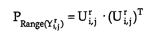
- Once this operator has been calculated, for each image portion Ri,j the projection Proj(IRi,j ) and the projection error err_Proj(IRi,j ) are calculated as


- The watched scene will be signalled as anomalous (i.e. an event will be detected) if the projection error is greater than the respective threshold, i.e. if the following relationship is fulfilled:

- According to a preferred embodiment, the threshold Thri,j is determined automatically and is set to the r+1th singular value σr+1 of the matrix Yi,j, i.e. to the highest index singular value fulfilling the relationships

- Advantageously, the threshold can be set to kσr+1 with k>1 so as to take into account any background noise being present in the images.
- Since the validation frames FVAL should represent the scene in a normal situation, no event should be detected even in the worst conditions. Otherwise, the set of acquired training frames is not representative of the scene in a normal situation; according to the method, it will be necessary in this case to select a different learning set and to rebuild the matrix

- For the purpose of preventing a good set of training frames from being discarded because a validation frame (not the training frames) is not actually representative of a normal situation, in a preferred and advantageous embodiment the method provides for simulating the event detection on a plurality of validation frames.
- According to this embodiment of the method, the set of training frames will be changed if a number of events is detected which is greater that a preset percentage, e.g. 25%, calculated on the total number of measurements. For example, if the validation phase verifies 100 validation frames and detects 25 events, then the method will require the learning set to be rebuilt. According to a further advantageous embodiment, the normality matrix Yi,j will be regenerated by starting from a new learning set if the mean projection error
err_Proj of a plurality of validation images is greater than or equal to the threshold Thri,j. - The mean projection error err_Proj is calculated as

wherein "media" is a function which receives the projection errors err_Proj1, err_Proj2, err_Proj3... of the validation images and outputs the mean value thereof. - In another embodiment it is possible to calculate the maximum projection error
err_Proj MAX among the projection errors of a plurality of validation images. If said error is beyond a preset threshold, then the training phase will be repeated by rebuilding a new learning set. - In a preferred embodiment, the number of frames to be added depends on the difference between the mean projection error
err_Proj and the threshold. - As an alternative, a predetermined number of frames may be added which is dependent on the memory available in the buffer.
- Preferably, not all of the frames added to the learning set are consecutive.
- The maximum size of the learning set may be defined (at installation or production time) as a function of the available memory and computing power.
- During the learning phase, the method provides for storing a plurality of pieces of information which are useful for detecting an event. In particular, the following information is stored:
- the matrixes

- the thresholds Thri,j
- the number r of principal components of each region Ri,j which allows to optimize the matrix Yi,j.
- Once the learning phase is over, the video surveillance system can start the actual operating phase by acquiring current images of the supervised area in order to detect any events. Through the
video camera 5, a current image of the supervised area is acquired, in particular a frame F* of the video signal generated by the video camera. - The frame F* is subdivided into a plurality of regions Ri,j(F*) by means of the same grid previously used during the learning phase.
- For each region Ri,j(F*), a corresponding vector IRi,j(F*) is created, which is then projected on the principal components of Yi,j, i.e. on the space of the learning images, in order to evaluate the projection error

as described with reference to the validation phase. - Within each region Rij, an event will be detected if the projection error is greater than the threshold selected by the system for that same region Ri,j.
- These steps use the information stored during the learning phase.
-
Fig. 4 illustrates an example of event detection. The analysed frame F* shows a corridor, which is the same corridor as that shown inFigs. 1 and3 , wherein two people are present whose silhouettes occupy a portion of the frame; in the example ofFig. 4 , said silhouettes occupy seven regions Ri,j. - Only these regions Ri,j (highlighted by a white contour) occupied by people will have an error which is greater than the accepted threshold, thus triggering an alarm.
- Although the above-described algorithm provides for treating images as vectors, obviously the physical meaning of these operations should not be overlooked, such operations being also obtainable in different manners and through different steps.
- Detecting an event by evaluating the projection error of the image vector on the vectorial space of the images Range(Yi,j r) corresponds to comparing a current image Ri,j(F*) with an image corresponding to a linear combination of a plurality of reference images approximating, or coinciding with, respective learning images.
- This concept will become clearer when looking at
Fig. 5 . - The space Range(Yi,j r) is represented by the plane Γ in which the reference images

- Projecting a current image Ri,j(F*) on the plane Γ means comparing said image with the linear combination Ci of the reference images which is closer to the image Ri,j(F*) in the sense of the L2 norm.
- Rather than a pixel-by-pixel comparison, this is an image-by-image comparison; this means that, in addition to the values of the pixels of the image, the correlation thereof is also taken into account through the principal components analysis.
- Of course this comparison, which according to the preferred and advantageous embodiment of the present invention is synthesized by the step of projecting the vector corresponding to the current image on the space of the images Range(Yi,j r), may alternatively be obtained by comparing first the values of the single pixels and then the relationships among the pixels of a current image and of an image built during the learning phase and corresponding to a linear combination of images approximating, or coinciding with, images acquired in a normal situation.
- The advantages of the present invention are apparent from the above description.
- The proposed approach, based on a comparison between portions of the current image (i.e. groups of pixels) and respective models built during the learning phase, turns out to be more reliable than known solutions based on a comparison of each pixel, in that it allows to take also into account the spatial correlation among the pixels.
- Furthermore, unlike known solutions using a statistic model in order to represent the normal situation of one pixel, the model according to the invention consists of a set of vectorial spaces, each pertaining to one region of the image, obtained from a learning phase.
- As a result, therefore, the model according to the invention allows to represent normality in a much more accurate manner than the solutions known in the art, since it uses images rather than statistical parameters such as average and variance.
- Also, PCA is an information compression method which allows to rebuild the original data (this not being possible with the statistic methods used by existing solutions), thus not endangering the quality with which normality is described and the resulting detection reliability.
- The proposed approach also offers a high degree of automation, unlike traditional approaches which require arbitrary choices when programming and setting up the system.
- In particular, the detection threshold is calculated automatically based on the learning data. Moreover, the proposed approach selects the length of the learning buffer autonomously depending on the dynamics being present in the watched scene during the learning phase. In particular, the algorithm chooses a compromise solution between available memory and scene dynamics.
- Furthermore, the minimum number of principal components used for representing the vectorial space also changes as a function of the scene dynamics and is also calculated by the algorithm.
- It is also clear that the above description presents a video surveillance system and an event detection method according to preferred embodiments which represent non-limiting examples of realization of the system and of implementation of the method.
- In particular, the selection of the optimum number of components ri,j, which allows to reduce the informative content of the matrix Yi,j, can be carried out in several different manners.
- For example, the ri,j principal components may be chosen by picking up those associated with a singular value being greater than a percentage (preferably in the range of 1-4%, more preferably 2%) of the greatest singular value (σ1) of the matrix Yi,j.
- For example, if the matrix Yi,j has the following singular values: σ1=100, σ2=20, σ3=10, σ4=1, σ5=0,5, σ6=0,3 ..., by accepting singular values greater than 2% of σ1 only the first three principal components u1, u2, u3 will be taken into consideration.
- Furthermore, the projection error, which in the preferred embodiment is calculated as err_Proj(IRi,j )=∥Proj(IRi,j )-IRi,j∥2 , may without distinction be calculated as any Lp norm:

Claims (20)
- Event detection method for video surveillance systems (1), comprising a learning phase, wherein learning images of a supervised area are acquired at different times in the absence of any detectable events, and an operating detection phase, wherein current images of said area are acquired, wherein an event is detected by comparing a current image with an image corresponding to a linear combination of a plurality of reference images approximating, or coinciding with, respective learning images, characterized in that said learning phase comprises
a training phase adapted to select a learning set consisting of said respective learning images, and
a validation phase comprising at least one simulation step for simulating said operating phase, said simulation step being carried out by comparing a validation image with a linear combination of said reference images, said validation image being a learning image not belonging to said learning set,
wherein said validation phase comprises the steps of:- projecting a plurality of image vectors, corresponding to a plurality of validation images, on the vectorial space defined by all of the linear combinations of said reference images as a whole,- for each projection, detecting a projection error defined as the norm of the difference between an image vector and the vector corresponding to the projection of the image vector on said vectorial space.- determining the maximum projection errorerr_Proj MAX of all projections of said plurality of image vectors,- repeating the training phase by changing the learning set, if the maximum projection errorerr_Proj MAX is greater than or equal to a certain threshold. - Method according to claim 1, characterized in that said reference images are obtained by using a method for analysing the principal components of a learning set consisting of a plurality of learning images.
- Method according to claim 2, wherein said learning set is organised in a normality matrix, the columns of which contain the pixels of said learning images, and said reference images are the columns of a matrix (Yi,j r) approximating said normality matrix (Yi,j).
- Method according to claim 3, characterized in that said method of principal components analysis comprises a step of decomposing said normality matrix into singular values, this decomposition providing three matrixes


and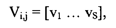
such that the normality matrix Yi,j can be written as: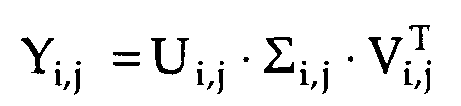
- Method according to claim 4, wherein said matrix approximating said normality matrix is


the number r of columns of the matrixes
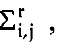

- Method according to any of claims 3 to 5, wherein said matrix approximating the normality matrix is such that the sum of its singular values is smaller than a preset percentage, preferably 75%, of the sum of the singular values of the normality matrix.
- Method according to any of claims 3 to 5, wherein the singular values of said matrix approximating the normality matrix are greater than a preset percentage, preferably between 2% and 4%, of the greatest singular value of said normality matrix.
- Method according to any of the preceding claims, characterized in that said comparison comprises the step of projecting an image vector, corresponding to said current image, on the vectorial space defined by all of the linear combinations of the reference images as a whole.
- Method according to claim 8, characterized in that an event will be detected if the following relationship is fulfilled:

wherein Thr is a threshold and err_Proj(IR) is a projection error calculated as the norm of the difference between the vectors IR and Proj(IR), IR being said image vector and Proj(IR) being the vector corresponding to the projection of IR on said vectorial space. - Method according to claim 9 when claim 8 is dependent on any of claims 2 to 7, wherein said normality matrix and said approximating matrix have a plurality of singular values in common, characterized in that said selected threshold is equal to the greatest non-common singular value.
- Method according to claim 9 when claim 8 is dependent on any of claims 2 to 7, wherein said normality matrix and said approximating matrix have a plurality of singular values in common, characterized in that said selected threshold is equal to the greatest non-common singular value multiplied by a preset real number greater than one.
- Method according to claim 10, characterized in that said selected threshold is equal to a preset percentage between 2% and 4% of the greatest singular value of said normality matrix.
- Method according to claim 1, characterized in that the training phase will be repeated by changing the learning set if said validation phase detects an event.
- Method according to claim 1 , characterized in that the training phase will be repeated by changing the learning set, if said validation phase detects a percentage of events which is greater than a preset threshold.
- Method according to any of the preceding claims, characterized in that image processing steps are carried out during both the learning phase and the event detection phase.
- Method according to claim 15, wherein said image processing steps comprise a step for reducing said images to greyscale.
- Method according to claim 15 or 16, wherein said image processing steps comprise a low-pass filtering step preferably using a Gaussian kernel.
- Method according to any of the preceding claims, wherein said learning images and said current images are groups of pixels obtained by subdividing frames or half-frames of a video signal by means of a predefined grid.
- Computer product which can be loaded in a memory area of an electronic computer and which comprises code portions adapted to implement the method according to any of claims 1 to 18 when executed by said computer.
- Video surveillance system (1) comprising at least one image acquisition unit (5) connected to an image processing unit (4), said image processing unit (4) being adapted to implement the method according to any of claims 1 to 18.
Applications Claiming Priority (2)
| Application Number | Priority Date | Filing Date | Title |
|---|---|---|---|
| IT000556A ITTO20060556A1 (en) | 2006-07-27 | 2006-07-27 | EVENT MEASUREMENT METHOD AND VIDEO SYSTEM SURVEILLANCE USING THE METHOD |
| PCT/IB2007/002050 WO2008012631A1 (en) | 2006-07-27 | 2007-07-20 | Event detection method and video surveillance system using said method |
Publications (2)
| Publication Number | Publication Date |
|---|---|
| EP1908016A1 EP1908016A1 (en) | 2008-04-09 |
| EP1908016B1 true EP1908016B1 (en) | 2010-06-23 |
Family
ID=38670734
Family Applications (1)
| Application Number | Title | Priority Date | Filing Date |
|---|---|---|---|
| EP07789499A Not-in-force EP1908016B1 (en) | 2006-07-27 | 2007-07-20 | Event detection method and video surveillance system using said method |
Country Status (11)
| Country | Link |
|---|---|
| US (1) | US20090310855A1 (en) |
| EP (1) | EP1908016B1 (en) |
| JP (1) | JP2009545223A (en) |
| CN (1) | CN101501729A (en) |
| AT (1) | ATE472142T1 (en) |
| BR (1) | BRPI0714646A2 (en) |
| CA (1) | CA2658020A1 (en) |
| DE (1) | DE602007007267D1 (en) |
| IT (1) | ITTO20060556A1 (en) |
| RU (1) | RU2009106852A (en) |
| WO (1) | WO2008012631A1 (en) |
Families Citing this family (8)
| Publication number | Priority date | Publication date | Assignee | Title |
|---|---|---|---|---|
| US8947495B2 (en) * | 2011-12-06 | 2015-02-03 | Alcatel Lucent | Telepresence apparatus for immersion of a human image in a physical environment |
| KR102217186B1 (en) * | 2014-04-11 | 2021-02-19 | 삼성전자주식회사 | Broadcasting receiving apparatus and method for providing summary contents service |
| GB201512283D0 (en) | 2015-07-14 | 2015-08-19 | Apical Ltd | Track behaviour events |
| CN106407657A (en) * | 2016-08-31 | 2017-02-15 | 无锡雅座在线科技发展有限公司 | Method and device for capturing event |
| US10303954B2 (en) * | 2017-02-22 | 2019-05-28 | Sas Institute Inc. | Monitoring, detection, and surveillance system using principal component analysis with machine and sensor data |
| EP3809366A1 (en) * | 2019-10-15 | 2021-04-21 | Aisapack Holding SA | Manufacturing method |
| CN113111843B (en) * | 2021-04-27 | 2023-12-29 | 北京赛博云睿智能科技有限公司 | Remote image data acquisition method and system |
| CN115767040B (en) * | 2023-01-06 | 2023-04-25 | 松立控股集团股份有限公司 | 360-degree panoramic monitoring automatic cruising method based on interactive continuous learning |
Family Cites Families (1)
| Publication number | Priority date | Publication date | Assignee | Title |
|---|---|---|---|---|
| GB2409029A (en) | 2003-12-11 | 2005-06-15 | Sony Uk Ltd | Face detection |
-
2006
- 2006-07-27 IT IT000556A patent/ITTO20060556A1/en unknown
-
2007
- 2007-07-20 CN CNA2007800301492A patent/CN101501729A/en active Pending
- 2007-07-20 AT AT07789499T patent/ATE472142T1/en not_active IP Right Cessation
- 2007-07-20 DE DE602007007267T patent/DE602007007267D1/en active Active
- 2007-07-20 WO PCT/IB2007/002050 patent/WO2008012631A1/en not_active Ceased
- 2007-07-20 US US12/374,342 patent/US20090310855A1/en not_active Abandoned
- 2007-07-20 EP EP07789499A patent/EP1908016B1/en not_active Not-in-force
- 2007-07-20 RU RU2009106852/08A patent/RU2009106852A/en not_active Application Discontinuation
- 2007-07-20 JP JP2009521364A patent/JP2009545223A/en active Pending
- 2007-07-20 CA CA002658020A patent/CA2658020A1/en not_active Abandoned
- 2007-07-20 BR BRPI0714646-9A2A patent/BRPI0714646A2/en not_active Application Discontinuation
Also Published As
| Publication number | Publication date |
|---|---|
| CN101501729A (en) | 2009-08-05 |
| ITTO20060556A1 (en) | 2008-01-28 |
| BRPI0714646A2 (en) | 2013-10-01 |
| EP1908016A1 (en) | 2008-04-09 |
| DE602007007267D1 (en) | 2010-08-05 |
| RU2009106852A (en) | 2010-09-10 |
| WO2008012631A1 (en) | 2008-01-31 |
| CA2658020A1 (en) | 2008-01-31 |
| JP2009545223A (en) | 2009-12-17 |
| US20090310855A1 (en) | 2009-12-17 |
| ATE472142T1 (en) | 2010-07-15 |
Similar Documents
| Publication | Publication Date | Title |
|---|---|---|
| CN111291718B (en) | Behavior prediction method and device, gait recognition method and device | |
| CN114926781B (en) | Multi-person time-space domain abnormal behavior positioning method and system supporting real-time monitoring scene | |
| Lin et al. | Estimation of number of people in crowded scenes using perspective transformation | |
| US20090310855A1 (en) | Event detection method and video surveillance system using said method | |
| JPH05501770A (en) | Dynamic object recognition method and its image processing system | |
| US7574039B2 (en) | Video based fire detection system | |
| CN112487891A (en) | Visual intelligent dynamic recognition model construction method applied to electric power operation site | |
| US8125522B2 (en) | Spurious motion filter | |
| CN118334747B (en) | Operation violation identification method combining multiple spatial scale features | |
| CN119229260A (en) | Method and system for identifying irregularities in lottery stores | |
| US8442278B2 (en) | Covariance based face association | |
| Raif et al. | Metamorphic testing for edge real-time face recognition and intrusion detection solution | |
| Foresti et al. | Event classification for automatic visual-based surveillance of parking lots | |
| CN109240123A (en) | On-loop simulation method and system for intelligent logistics vehicle | |
| CN116129502B (en) | Training method and device for human face fake video detection model and computing equipment | |
| CN111402185B (en) | Image detection method and device | |
| Gal | Automatic obstacle detection for USV’s navigation using vision sensors | |
| CN115830517B (en) | Video-based examination room abnormal frame extraction method and system | |
| CN117975405A (en) | Inspection track monitoring method and device based on deep learning | |
| HK1137560A (en) | Event detection method and video surveillance system using said method | |
| CN112634233A (en) | Application method in power distribution equipment based on image detection and analysis technology | |
| CN118101899B (en) | A security monitoring storage information intelligent analysis management method and system | |
| CN120726576B (en) | Intelligent security anomaly identification method and device | |
| KR102870989B1 (en) | Method and apparatus for detecting invasion | |
| CN121838055A (en) | Project operation safety monitoring method and device, storage medium and computer equipment |
Legal Events
| Date | Code | Title | Description |
|---|---|---|---|
| PUAI | Public reference made under article 153(3) epc to a published international application that has entered the european phase |
Free format text: ORIGINAL CODE: 0009012 |
|
| 17P | Request for examination filed |
Effective date: 20080201 |
|
| AK | Designated contracting states |
Kind code of ref document: A1 Designated state(s): AT BE BG CH CY CZ DE DK EE ES FI FR GB GR HU IE IS IT LI LT LU LV MC MT NL PL PT RO SE SI SK TR |
|
| AX | Request for extension of the european patent |
Extension state: AL BA HR MK RS |
|
| 17Q | First examination report despatched |
Effective date: 20080724 |
|
| DAX | Request for extension of the european patent (deleted) | ||
| GRAP | Despatch of communication of intention to grant a patent |
Free format text: ORIGINAL CODE: EPIDOSNIGR1 |
|
| GRAS | Grant fee paid |
Free format text: ORIGINAL CODE: EPIDOSNIGR3 |
|
| GRAA | (expected) grant |
Free format text: ORIGINAL CODE: 0009210 |
|
| AK | Designated contracting states |
Kind code of ref document: B1 Designated state(s): AT BE BG CH CY CZ DE DK EE ES FI FR GB GR HU IE IS IT LI LT LU LV MC MT NL PL PT RO SE SI SK TR |
|
| REG | Reference to a national code |
Ref country code: CH Ref legal event code: EP |
|
| REG | Reference to a national code |
Ref country code: IE Ref legal event code: FG4D |
|
| REF | Corresponds to: |
Ref document number: 602007007267 Country of ref document: DE Date of ref document: 20100805 Kind code of ref document: P |
|
| REG | Reference to a national code |
Ref country code: SE Ref legal event code: TRGR |
|
| REG | Reference to a national code |
Ref country code: NL Ref legal event code: VDEP Effective date: 20100623 |
|
| PG25 | Lapsed in a contracting state [announced via postgrant information from national office to epo] |
Ref country code: LT Free format text: LAPSE BECAUSE OF FAILURE TO SUBMIT A TRANSLATION OF THE DESCRIPTION OR TO PAY THE FEE WITHIN THE PRESCRIBED TIME-LIMIT Effective date: 20100623 |
|
| LTIE | Lt: invalidation of european patent or patent extension |
Effective date: 20100623 |
|
| PG25 | Lapsed in a contracting state [announced via postgrant information from national office to epo] |
Ref country code: SI Free format text: LAPSE BECAUSE OF FAILURE TO SUBMIT A TRANSLATION OF THE DESCRIPTION OR TO PAY THE FEE WITHIN THE PRESCRIBED TIME-LIMIT Effective date: 20100623 Ref country code: AT Free format text: LAPSE BECAUSE OF FAILURE TO SUBMIT A TRANSLATION OF THE DESCRIPTION OR TO PAY THE FEE WITHIN THE PRESCRIBED TIME-LIMIT Effective date: 20100623 Ref country code: FI Free format text: LAPSE BECAUSE OF FAILURE TO SUBMIT A TRANSLATION OF THE DESCRIPTION OR TO PAY THE FEE WITHIN THE PRESCRIBED TIME-LIMIT Effective date: 20100623 Ref country code: LV Free format text: LAPSE BECAUSE OF FAILURE TO SUBMIT A TRANSLATION OF THE DESCRIPTION OR TO PAY THE FEE WITHIN THE PRESCRIBED TIME-LIMIT Effective date: 20100623 |
|
| PG25 | Lapsed in a contracting state [announced via postgrant information from national office to epo] |
Ref country code: PL Free format text: LAPSE BECAUSE OF FAILURE TO SUBMIT A TRANSLATION OF THE DESCRIPTION OR TO PAY THE FEE WITHIN THE PRESCRIBED TIME-LIMIT Effective date: 20100623 |
|
| PG25 | Lapsed in a contracting state [announced via postgrant information from national office to epo] |
Ref country code: EE Free format text: LAPSE BECAUSE OF FAILURE TO SUBMIT A TRANSLATION OF THE DESCRIPTION OR TO PAY THE FEE WITHIN THE PRESCRIBED TIME-LIMIT Effective date: 20100623 Ref country code: NL Free format text: LAPSE BECAUSE OF FAILURE TO SUBMIT A TRANSLATION OF THE DESCRIPTION OR TO PAY THE FEE WITHIN THE PRESCRIBED TIME-LIMIT Effective date: 20100623 |
|
| PG25 | Lapsed in a contracting state [announced via postgrant information from national office to epo] |
Ref country code: MC Free format text: LAPSE BECAUSE OF NON-PAYMENT OF DUE FEES Effective date: 20100731 Ref country code: CZ Free format text: LAPSE BECAUSE OF FAILURE TO SUBMIT A TRANSLATION OF THE DESCRIPTION OR TO PAY THE FEE WITHIN THE PRESCRIBED TIME-LIMIT Effective date: 20100623 Ref country code: IS Free format text: LAPSE BECAUSE OF FAILURE TO SUBMIT A TRANSLATION OF THE DESCRIPTION OR TO PAY THE FEE WITHIN THE PRESCRIBED TIME-LIMIT Effective date: 20101023 Ref country code: BE Free format text: LAPSE BECAUSE OF FAILURE TO SUBMIT A TRANSLATION OF THE DESCRIPTION OR TO PAY THE FEE WITHIN THE PRESCRIBED TIME-LIMIT Effective date: 20100623 Ref country code: CY Free format text: LAPSE BECAUSE OF FAILURE TO SUBMIT A TRANSLATION OF THE DESCRIPTION OR TO PAY THE FEE WITHIN THE PRESCRIBED TIME-LIMIT Effective date: 20100623 Ref country code: PT Free format text: LAPSE BECAUSE OF FAILURE TO SUBMIT A TRANSLATION OF THE DESCRIPTION OR TO PAY THE FEE WITHIN THE PRESCRIBED TIME-LIMIT Effective date: 20101025 Ref country code: RO Free format text: LAPSE BECAUSE OF FAILURE TO SUBMIT A TRANSLATION OF THE DESCRIPTION OR TO PAY THE FEE WITHIN THE PRESCRIBED TIME-LIMIT Effective date: 20100623 Ref country code: SK Free format text: LAPSE BECAUSE OF FAILURE TO SUBMIT A TRANSLATION OF THE DESCRIPTION OR TO PAY THE FEE WITHIN THE PRESCRIBED TIME-LIMIT Effective date: 20100623 |
|
| PG25 | Lapsed in a contracting state [announced via postgrant information from national office to epo] |
Ref country code: DK Free format text: LAPSE BECAUSE OF FAILURE TO SUBMIT A TRANSLATION OF THE DESCRIPTION OR TO PAY THE FEE WITHIN THE PRESCRIBED TIME-LIMIT Effective date: 20100623 |
|
| PLBE | No opposition filed within time limit |
Free format text: ORIGINAL CODE: 0009261 |
|
| STAA | Information on the status of an ep patent application or granted ep patent |
Free format text: STATUS: NO OPPOSITION FILED WITHIN TIME LIMIT |
|
| PG25 | Lapsed in a contracting state [announced via postgrant information from national office to epo] |
Ref country code: GR Free format text: LAPSE BECAUSE OF FAILURE TO SUBMIT A TRANSLATION OF THE DESCRIPTION OR TO PAY THE FEE WITHIN THE PRESCRIBED TIME-LIMIT Effective date: 20100924 |
|
| 26N | No opposition filed |
Effective date: 20110324 |
|
| REG | Reference to a national code |
Ref country code: FR Ref legal event code: ST Effective date: 20110531 |
|
| REG | Reference to a national code |
Ref country code: DE Ref legal event code: R097 Ref document number: 602007007267 Country of ref document: DE Effective date: 20110323 |
|
| PG25 | Lapsed in a contracting state [announced via postgrant information from national office to epo] |
Ref country code: FR Free format text: LAPSE BECAUSE OF NON-PAYMENT OF DUE FEES Effective date: 20100823 Ref country code: IE Free format text: LAPSE BECAUSE OF NON-PAYMENT OF DUE FEES Effective date: 20100720 |
|
| PG25 | Lapsed in a contracting state [announced via postgrant information from national office to epo] |
Ref country code: MT Free format text: LAPSE BECAUSE OF FAILURE TO SUBMIT A TRANSLATION OF THE DESCRIPTION OR TO PAY THE FEE WITHIN THE PRESCRIBED TIME-LIMIT Effective date: 20100623 |
|
| REG | Reference to a national code |
Ref country code: CH Ref legal event code: PL |
|
| GBPC | Gb: european patent ceased through non-payment of renewal fee |
Effective date: 20110720 |
|
| PG25 | Lapsed in a contracting state [announced via postgrant information from national office to epo] |
Ref country code: LI Free format text: LAPSE BECAUSE OF NON-PAYMENT OF DUE FEES Effective date: 20110731 Ref country code: CH Free format text: LAPSE BECAUSE OF NON-PAYMENT OF DUE FEES Effective date: 20110731 |
|
| PG25 | Lapsed in a contracting state [announced via postgrant information from national office to epo] |
Ref country code: GB Free format text: LAPSE BECAUSE OF NON-PAYMENT OF DUE FEES Effective date: 20110720 |
|
| PG25 | Lapsed in a contracting state [announced via postgrant information from national office to epo] |
Ref country code: LU Free format text: LAPSE BECAUSE OF NON-PAYMENT OF DUE FEES Effective date: 20100720 Ref country code: HU Free format text: LAPSE BECAUSE OF FAILURE TO SUBMIT A TRANSLATION OF THE DESCRIPTION OR TO PAY THE FEE WITHIN THE PRESCRIBED TIME-LIMIT Effective date: 20101224 Ref country code: BG Free format text: LAPSE BECAUSE OF FAILURE TO SUBMIT A TRANSLATION OF THE DESCRIPTION OR TO PAY THE FEE WITHIN THE PRESCRIBED TIME-LIMIT Effective date: 20100623 |
|
| PG25 | Lapsed in a contracting state [announced via postgrant information from national office to epo] |
Ref country code: TR Free format text: LAPSE BECAUSE OF FAILURE TO SUBMIT A TRANSLATION OF THE DESCRIPTION OR TO PAY THE FEE WITHIN THE PRESCRIBED TIME-LIMIT Effective date: 20100623 |
|
| PG25 | Lapsed in a contracting state [announced via postgrant information from national office to epo] |
Ref country code: BG Free format text: LAPSE BECAUSE OF FAILURE TO SUBMIT A TRANSLATION OF THE DESCRIPTION OR TO PAY THE FEE WITHIN THE PRESCRIBED TIME-LIMIT Effective date: 20100923 |
|
| PG25 | Lapsed in a contracting state [announced via postgrant information from national office to epo] |
Ref country code: ES Free format text: LAPSE BECAUSE OF FAILURE TO SUBMIT A TRANSLATION OF THE DESCRIPTION OR TO PAY THE FEE WITHIN THE PRESCRIBED TIME-LIMIT Effective date: 20101004 |
|
| PGFP | Annual fee paid to national office [announced via postgrant information from national office to epo] |
Ref country code: IT Payment date: 20180731 Year of fee payment: 12 Ref country code: DE Payment date: 20180730 Year of fee payment: 12 |
|
| PGFP | Annual fee paid to national office [announced via postgrant information from national office to epo] |
Ref country code: SE Payment date: 20180725 Year of fee payment: 12 |
|
| REG | Reference to a national code |
Ref country code: DE Ref legal event code: R119 Ref document number: 602007007267 Country of ref document: DE |
|
| REG | Reference to a national code |
Ref country code: SE Ref legal event code: EUG |
|
| PG25 | Lapsed in a contracting state [announced via postgrant information from national office to epo] |
Ref country code: DE Free format text: LAPSE BECAUSE OF NON-PAYMENT OF DUE FEES Effective date: 20200201 Ref country code: SE Free format text: LAPSE BECAUSE OF NON-PAYMENT OF DUE FEES Effective date: 20190721 |
|
| PG25 | Lapsed in a contracting state [announced via postgrant information from national office to epo] |
Ref country code: IT Free format text: LAPSE BECAUSE OF NON-PAYMENT OF DUE FEES Effective date: 20190720 |