EP1908342A1 - Faneuse - Google Patents
Faneuse Download PDFInfo
- Publication number
- EP1908342A1 EP1908342A1 EP07019068A EP07019068A EP1908342A1 EP 1908342 A1 EP1908342 A1 EP 1908342A1 EP 07019068 A EP07019068 A EP 07019068A EP 07019068 A EP07019068 A EP 07019068A EP 1908342 A1 EP1908342 A1 EP 1908342A1
- Authority
- EP
- European Patent Office
- Prior art keywords
- bearing
- control lever
- machine according
- haymaking machine
- rake
- Prior art date
- Legal status (The legal status is an assumption and is not a legal conclusion. Google has not performed a legal analysis and makes no representation as to the accuracy of the status listed.)
- Withdrawn
Links
- 238000012423 maintenance Methods 0.000 description 2
- 206010012239 Delusion Diseases 0.000 description 1
- 239000000969 carrier Substances 0.000 description 1
- 125000004122 cyclic group Chemical class 0.000 description 1
- 231100000868 delusion Toxicity 0.000 description 1
- 230000001419 dependent effect Effects 0.000 description 1
- 230000006355 external stress Effects 0.000 description 1
- 230000002349 favourable effect Effects 0.000 description 1
- 210000004907 gland Anatomy 0.000 description 1
- 238000003780 insertion Methods 0.000 description 1
- 230000037431 insertion Effects 0.000 description 1
- 230000035882 stress Effects 0.000 description 1
Images


Classifications
-
- A—HUMAN NECESSITIES
- A01—AGRICULTURE; FORESTRY; ANIMAL HUSBANDRY; HUNTING; TRAPPING; FISHING
- A01D—HARVESTING; MOWING
- A01D78/00—Haymakers with tines moving with respect to the machine
- A01D78/08—Haymakers with tines moving with respect to the machine with tine-carrying rotary heads or wheels
- A01D78/10—Haymakers with tines moving with respect to the machine with tine-carrying rotary heads or wheels the tines rotating about a substantially vertical axis
- A01D78/12—Haymakers with tines moving with respect to the machine with tine-carrying rotary heads or wheels the tines rotating about a substantially vertical axis the tines having an additional movement superimposed upon their rotary movement
- A01D78/125—Haymakers with tines moving with respect to the machine with tine-carrying rotary heads or wheels the tines rotating about a substantially vertical axis the tines having an additional movement superimposed upon their rotary movement by a guiding track
Definitions
- the present invention relates to a haymaking machine, in particular a rotary rake, comprising at least one rake, which is circumferentially drivable about a raking rotary axis and is rotatably supported by a rotary bearing about its longitudinal axis, wherein the control arm, a control lever is rotatably connected, which can be brought into engagement with a curved path and controls the rotational position of the raking arm as a function of the circulating position of the raking arm about the vertical axis of the rake.
- Rotary swathers regularly have one or more rotary rakes, which rotate in their operating position to a substantially upright rotary rake axis.
- Each rotary rake usually comprises a plurality of recharters, which protrude in a star shape from the hub of the rotary rake and carry rake tines at their projecting ends.
- the individual recharms are cyclically rotated about their own longitudinal axis as they circulate about the rotary axis, whereby the rake tines in a particular segment of the orbit are directed downwards to catch crop on the ground as they move in another segment of the circulation circuit are flipped up to sweep across the crop.
- This cyclic rotation of the Recharme in response to their orbital motion is usually accomplished via control levers which are rotatably connected to the inner, hub-side end of the Recharme with the latter and run on a Kurvenbahn- or control path which extends around the Rechnikelachse.
- the bearing assembly should be made such that the ease of assembly and maintenance of Recharm- and control lever assembly is as high as possible. In particular, it is desirable not to have to disassemble the entire hub and bearing housing assembly in order to replace or repair a Recharm or the rotatably mounted control lever.
- the present invention seeks to provide an improved haymaking machine of the type mentioned, which avoids the disadvantages of the prior art and the latter further develops in an advantageous manner.
- a stable and rigid bearing assembly for the Recharme should be created, which allows easy insertion and removal of individual Recharme or control lever.
- Inner side means the side of the control lever, which is remote from the raking arm attached to the rake or closer to the rake rotor axis than the cantilevered outer ends of the Recharme, where the rake tines are attached.
- this increases the level of the inner bearing point to a further outer bearing point of the respective Recharms, whereby a stiffer and more stable storage of Recharme can be achieved.
- the arrangement of the inner bearing on the side facing away from the rake tines inner side of the control lever is also advantageous in terms of ease of assembly and maintenance, as this accessibility and mountability of the control lever from the outside is not hindered by the bearing.
- the Recharme are often not actually arranged in the mathematical-geometric sense radially to Rech Vietnameseelachse, but are tangentially arranged with respect to an imaginary, smaller circle around the Rech Vietnameseelachse, means the aforementioned "inner" side of the control lever is not necessarily the actual radially inner side of the control lever; Rather, what is meant is the side of the control lever facing away from the rake tines on the projecting end of the Recharme.
- a releasable plug connection can be provided, which allows the Recharm together with the attached control lever, possibly after loosening the outer bearing and attached thereto Delusions, the Recharm together with the attached control lever to pull outward from the inner bearing point or vice versa from the outside to insert the Recharm with the attached control lever in the inner bearing.
- the arrangement of the inner bearing point on the aforementioned inner side of the control lever it is possible in a simple manner to provide in further development of the invention on both sides of the control lever bearing points for the storage of the Recharms.
- the control lever and thus the point of introduction for the touching of the control lever forth forces is accordingly between the two bearing points of the pivot bearing, whereby a particularly rigid and stable storage of Recharme is possible.
- the outer bearing of the control lever is clearly spaced, preferably at the outer edge of a plate-shaped carrier or bearing housing to which the Recharme of the rotary rake are attached and which can rotate about the Rechnikelachse. As a result, a maximum bearing distance is achieved.
- the inner bearing is disposed adjacent to the respective control lever adjacent, so that in the sense of a favorable power flow, a direct power dissipation of the forces introduced by the control levers forth can be done.
- the inner bearing point is arranged directly at the control lever.
- control lever can be rotatably mounted even at the inner bearing point.
- the arithmetic arm it would also be possible for the arithmetic arm to protrude beyond the attachment point of the control lever and to be supported by this protruding inner end portion alone at the inner bearing point.
- the aforementioned arrangement according to which the control lever itself is supported on the inner bearing point, improves the Force derivative with respect to the forces introduced by the control lever or the load on the connection point between the arm and the control lever can be reduced.
- control lever is connected to a control lever bearing piece which is rigidly connectable to the Recharm and having a pivot bearing portion which is supported on said inner bearing of the pivot bearing of the Recharms.
- the said control lever bearing piece can basically be designed differently. According to an advantageous embodiment of the invention, it may at least partially form a sleeve which engages around the preferably tubular and / or wavy arm. According to an advantageous embodiment of the invention, this sleeve-shaped bearing piece may have an end projection which sits in the inner bearing, whereby the arithmetic arm is also rotatably mounted on the pivot bearing of the control lever at the inner bearing point.
- the bearings of the Recharmlagerung can basically be arranged differently, for example, all attached to a common carrier or be arranged individually or in groups on different carriers.
- the inner bearings are attached to a preferably approximately plate-shaped, common carrier which is rotatably mounted about the vertical axis and possibly also act as a drive piece, for example, can be operatively connected to a rotary rake drive gear or its driven piece.
- the outer bearings for the Recharme can in principle be attached to the same, said plate-shaped carrier.
- the outer bearings can also be attached to a separate rake rotor housing piece, which together with the aforementioned plate-shaped carrier forms a hub structure on which the Recharme the rotary rake are suspended.
- the outer bearings are detachable, so that the Recharme can be easily pulled out after loosening the outer bearings together with the control lever to the outside, with the connector dissolves at the inner bearings.
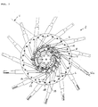
- the rotary swather 1 shown by way of example in FIG. 1 has, in a manner known per se, a machine frame 1 with which the rotary swather can be coupled to a tractor not specifically shown.
- a single rotary rake 2 is rotatably driven to drive in the working position substantially vertical rotary rake axis 3 in the illustrated embodiment.
- the centrifugal drive which is not shown in detail, can take place mechanically, hydraulically or electrically.
- an angle gear is provided with a connecting pipe or a central tube to the gyro and gyro.
- the rotary rake 2 has a plurality of - roughly speaking - radially arranged to the rotary rake axis 3 Recharme 4, at whose projecting ends 40 rake tines 5 are attached.
- the Recharme 4 are thereby rotated about its orbital axis 3 about its own longitudinal axis 42 in its orbit, so that the attached rake tines 5 can be pivoted up and down to touch one hand to collapse the crop close to the ground and on the other hand in the field of the swath to fold up to store the crop in the said swath.
- the rake tines 5 are folded in the direction of travel in the rear sector of the orbit upwards and in the forward sector of the orbit down.
- control arms 7 are attached to the inner ends 41 of the Recharme, which rotatably with the Recharmen 4 in the illustrated embodiment by a respective screw 8 are connected.
- the said control lever 7 thereby collar of the Recharmen 4 such that they have a lever arm with respect to the longitudinal axis 42.
- control levers 7 run on a curved path 9, which extends around the rotary axis 3 and seen in the running direction of the control lever 7 has gradients and depressions, so that the control lever 7 is pivoted and thereby the Recharme 4 are rotated about its longitudinal axis 42 ,
- control lever 7 carry engagement wheels 10, by means of which they run on the cam track 9.
- Said cam track 9 is advantageously adjustably attached to the hub structure 11, in particular a central tube, in order to be able to set the desired pivoting of the rake tines 5.
- the said central tube can be part of a drive gear 12 or be connected to this, which converts the drive movement of the mechanical drive in the illustrated embodiment in a circulation movement of the Recharme 4 to the Rechnikelachse 3.
- the rechargments 4 which extend in a star-shaped manner away from the raking-rotor axis or a circular arc, are provided by means of a Drehlagerung 13 rotatably mounted on the aforementioned hub structure 11 about its longitudinal axis 42.
- the pivot bearing 13 in this case comprises an outer bearing 14 and an inner bearing 15.
- the inner bearing 15 comprises sleeve or eye-shaped bearing segments 16, all of which are rigidly secured to a generally plate-shaped support 17 in the form of a bearing ring, which is rotatably mounted on the aforementioned drive gear 12 about the Rechnikelachse 3 and may be connected to a driven gear of said drive gear 12.
- the inner bearings 15 are arranged on the further inner side of the control lever 7, which faces away from the rake tines 5 of the respective Recharms 4. If you consider a respective Vercharm 4 from its outer end in its longitudinal direction, the inner bearing 15 is thus behind the respective control lever 7, and advantageously directly to the control lever 7.
- the control lever 7 are rigid with control lever bearing pieces 18, which are sleeve-shaped and are pushed onto the shaft or tubular Recharme 4.
- the said control lever bearing pieces 18 are rotatably connected by the aforementioned fittings 8 with the Recharmen 4.
- the inner bearings 15 can sit directly on these control lever bearing pieces 18, on a through the control lever bearing pieces 18 passing through Recharmendabterrorism and / or integrally formed on the respective control lever bearing piece 18 pivot bearing portion.
- the inner bearing 15 is advantageously connected to the Vercharm 4 and the attached control lever 7 by a plug connection, which can be solved by pulling out of the Vercharmes 4 to the outside or by inserting from the outside into engagement.
- the outer bearings 14 for the Recharme 4 could basically also be provided on the plate-shaped carrier 17 in the form of the bearing ring shown in Figure 3.
- the outer bearings 14 are attached to a bearing housing, which is connected to the aforementioned carrier 17 in the form of in FIG 3 bearing ring can be connected by means of a flange ring and glands to form a rigid, compact gyro unit.
- the outer bearings 14 may advantageously be detachably formed, for example, as indicated in Figure 2, 19 comprise detachable bearing segments by screwing.
- a to be serviced or exchanged Recharm can be easily removed by the fact that the outer bearing 14 is released and the Recharm is simply pulled outward.
- the inner bearing 15 dissolves by itself.
- the control lever 7 does not need to be disassembled beforehand by the inside arrangement of the bearing point 15, but can simply be pulled out with it.
Landscapes
- Life Sciences & Earth Sciences (AREA)
- Environmental Sciences (AREA)
- Harvester Elements (AREA)
Applications Claiming Priority (1)
| Application Number | Priority Date | Filing Date | Title |
|---|---|---|---|
| DE200620015108 DE202006015108U1 (de) | 2006-10-02 | 2006-10-02 | Heuwerbungsmaschine |
Publications (1)
| Publication Number | Publication Date |
|---|---|
| EP1908342A1 true EP1908342A1 (fr) | 2008-04-09 |
Family
ID=38895582
Family Applications (1)
| Application Number | Title | Priority Date | Filing Date |
|---|---|---|---|
| EP07019068A Withdrawn EP1908342A1 (fr) | 2006-10-02 | 2007-09-27 | Faneuse |
Country Status (2)
| Country | Link |
|---|---|
| EP (1) | EP1908342A1 (fr) |
| DE (1) | DE202006015108U1 (fr) |
Families Citing this family (2)
| Publication number | Priority date | Publication date | Assignee | Title |
|---|---|---|---|---|
| EP3357323B1 (fr) | 2017-02-02 | 2020-04-01 | Kverneland Group Kerteminde AS | Rainure de came réglable en hauteur |
| DE102018213212B4 (de) * | 2018-08-07 | 2026-02-05 | Kverneland Group Kerteminde As | Höhenverstellbare Kurvenbahn |
Citations (4)
| Publication number | Priority date | Publication date | Assignee | Title |
|---|---|---|---|---|
| DE3543729A1 (de) * | 1985-12-11 | 1987-06-19 | Karl Moosbrucker | Steuerung fuer kreiselschwader |
| EP0559023A1 (fr) * | 1992-03-02 | 1993-09-08 | Maschinenfabrik Bernard Krone GmbH | Râteau rotatif pour machine de fenaison |
| FR2842068A1 (fr) * | 2002-07-15 | 2004-01-16 | Kuhn Sa | Machine de fenaison comportant un rotor muni d'une liaison amelioree entre les outils de travail et le carter |
| DE20319025U1 (de) * | 2003-12-05 | 2004-03-11 | Gebr. Pöttinger GmbH | Kreiselrechen für eine Heuwerbungsmaschine |
-
2006
- 2006-10-02 DE DE200620015108 patent/DE202006015108U1/de not_active Expired - Lifetime
-
2007
- 2007-09-27 EP EP07019068A patent/EP1908342A1/fr not_active Withdrawn
Patent Citations (4)
| Publication number | Priority date | Publication date | Assignee | Title |
|---|---|---|---|---|
| DE3543729A1 (de) * | 1985-12-11 | 1987-06-19 | Karl Moosbrucker | Steuerung fuer kreiselschwader |
| EP0559023A1 (fr) * | 1992-03-02 | 1993-09-08 | Maschinenfabrik Bernard Krone GmbH | Râteau rotatif pour machine de fenaison |
| FR2842068A1 (fr) * | 2002-07-15 | 2004-01-16 | Kuhn Sa | Machine de fenaison comportant un rotor muni d'une liaison amelioree entre les outils de travail et le carter |
| DE20319025U1 (de) * | 2003-12-05 | 2004-03-11 | Gebr. Pöttinger GmbH | Kreiselrechen für eine Heuwerbungsmaschine |
Also Published As
| Publication number | Publication date |
|---|---|
| DE202006015108U1 (de) | 2008-02-21 |
Similar Documents
| Publication | Publication Date | Title |
|---|---|---|
| DE2366600C2 (de) | Kreiselheuwerbungsmaschine | |
| DE8022517U1 (de) | Heuwerbungsmaschine. | |
| DE2423326C2 (de) | Kreiselheuwerbungsmaschine | |
| EP0903077A1 (fr) | Ramasseur por recoltes | |
| EP2614698B1 (fr) | Faucheuse | |
| DE2462931C2 (de) | Kreiselheuwerbungsmaschine | |
| DE2448546C2 (de) | Heuwerbungsmaschine | |
| DE60210550T2 (de) | Heuwerbungsmaschine | |
| DE6610452U (de) | Kreiselheuwerbungsmaschine. | |
| DE2517464C2 (de) | Kreiselheuwerbungsmaschine | |
| EP1908342A1 (fr) | Faneuse | |
| DE2254509A1 (de) | Kreiselheuwerbungsmaschine | |
| DE1507295C3 (de) | Rechrad | |
| DE1800497C3 (de) | Heuwerbungsmaschine | |
| DE1757983A1 (de) | Heuerntemaschine | |
| DE2449413A1 (de) | Heuwerbungsmaschine | |
| DE3000564A1 (de) | Heuwerbungsmaschine | |
| DE3048014C2 (de) | Kreiselheuwerbungsmaschine | |
| DE2024167C3 (de) | Kreiselschwadrechen | |
| DE3000538A1 (de) | Heuwerbungsmaschine | |
| AT389620B (de) | Heuwerbungsmaschine | |
| DE1582461C3 (de) | Kreiselheuwerbungsmaschine | |
| DE2446735A1 (de) | Kreiselheuwerbungsmaschine | |
| DE102004028550A1 (de) | Haspel für eine Erntegutbergungseinrichtung | |
| DE2359574C2 (de) | Kreiselheuwerbungsmaschine |
Legal Events
| Date | Code | Title | Description |
|---|---|---|---|
| PUAI | Public reference made under article 153(3) epc to a published international application that has entered the european phase |
Free format text: ORIGINAL CODE: 0009012 |
|
| AK | Designated contracting states |
Kind code of ref document: A1 Designated state(s): AT BE BG CH CY CZ DE DK EE ES FI FR GB GR HU IE IS IT LI LT LU LV MC MT NL PL PT RO SE SI SK TR |
|
| AX | Request for extension of the european patent |
Extension state: AL BA HR MK RS |
|
| 17P | Request for examination filed |
Effective date: 20080505 |
|
| 17Q | First examination report despatched |
Effective date: 20080606 |
|
| AKX | Designation fees paid |
Designated state(s): AT BE BG CH CY CZ DE DK EE ES FI FR GB GR HU IE IS IT LI LT LU LV MC MT NL PL PT RO SE SI SK TR |
|
| STAA | Information on the status of an ep patent application or granted ep patent |
Free format text: STATUS: THE APPLICATION IS DEEMED TO BE WITHDRAWN |
|
| 18D | Application deemed to be withdrawn |
Effective date: 20120403 |