EP1908381B1 - Automatische Kochvorrichtung - Google Patents
Automatische Kochvorrichtung Download PDFInfo
- Publication number
- EP1908381B1 EP1908381B1 EP20060021054 EP06021054A EP1908381B1 EP 1908381 B1 EP1908381 B1 EP 1908381B1 EP 20060021054 EP20060021054 EP 20060021054 EP 06021054 A EP06021054 A EP 06021054A EP 1908381 B1 EP1908381 B1 EP 1908381B1
- Authority
- EP
- European Patent Office
- Prior art keywords
- rotating
- fixed
- rotating device
- automatic cooking
- cooking
- Prior art date
- Legal status (The legal status is an assumption and is not a legal conclusion. Google has not performed a legal analysis and makes no representation as to the accuracy of the status listed.)
- Not-in-force
Links
- 238000010411 cooking Methods 0.000 title claims description 73
- 230000033001 locomotion Effects 0.000 claims description 18
- 235000013305 food Nutrition 0.000 description 15
- 239000000796 flavoring agent Substances 0.000 description 6
- 235000019634 flavors Nutrition 0.000 description 6
- 235000012054 meals Nutrition 0.000 description 6
- 238000000034 method Methods 0.000 description 6
- 239000004615 ingredient Substances 0.000 description 4
- 238000002360 preparation method Methods 0.000 description 2
- 230000001154 acute effect Effects 0.000 description 1
- 238000004590 computer program Methods 0.000 description 1
- 238000010438 heat treatment Methods 0.000 description 1
- 230000001105 regulatory effect Effects 0.000 description 1
Images

Classifications
-
- A—HUMAN NECESSITIES
- A47—FURNITURE; DOMESTIC ARTICLES OR APPLIANCES; COFFEE MILLS; SPICE MILLS; SUCTION CLEANERS IN GENERAL
- A47J—KITCHEN EQUIPMENT; COFFEE MILLS; SPICE MILLS; APPARATUS FOR MAKING BEVERAGES
- A47J43/00—Implements for preparing or holding food, not provided for in other groups of this subclass
- A47J43/04—Machines for domestic use not covered elsewhere, e.g. for grinding, mixing, stirring, kneading, emulsifying, whipping or beating foodstuffs, e.g. power-driven
- A47J43/07—Parts or details, e.g. mixing tools, whipping tools
- A47J43/08—Driving mechanisms
- A47J43/087—Driving mechanisms for machines with several driving units
-
- A—HUMAN NECESSITIES
- A47—FURNITURE; DOMESTIC ARTICLES OR APPLIANCES; COFFEE MILLS; SPICE MILLS; SUCTION CLEANERS IN GENERAL
- A47J—KITCHEN EQUIPMENT; COFFEE MILLS; SPICE MILLS; APPARATUS FOR MAKING BEVERAGES
- A47J37/00—Baking; Roasting; Grilling; Frying
- A47J37/04—Roasting apparatus with movably-mounted food supports or with movable heating implements; Spits
- A47J37/047—Roasting apparatus with movably-mounted food supports or with movable heating implements; Spits with rotating drums or baskets
Definitions
- the present invention relates an improved cooking device, particularly, the present invention relates an automatic cooking device for general purpose heating, cooking in a house, restaurants and the like.
- the cooking devices with digital cooking programs control the cooking processes according to the food to be prepared become increasing popular in our daily life.
- Most of the prior art are designed to operate the cooking programs with only hot air or with only steam, or with a combination of hot air and steam at various temperatures and different time settings.
- the setting and use of such cooking devices requires special knowledge, particularly for cooking processes in which different cooking media are used for various periods of time at different temperatures. For most of people, those high-tech cooking devices are inconvenient and difficult to be operated.
- those cooking devices are not suitable to prepare food in the hot oil, such as stir-fry food, a common dish in the Chinese cuisine.
- the conventional cooking devices are restricted in its cooking programs in respect to certain type of food to be cooked, most of Asian cuisine cannot be prepared through hot air or steam, as a result, the conventional cooking devices cannot prepare various types of food.
- the invention has been made to resolve above-mentioned problems, and its object is to provide a computerized cooking device in which can automatically control and cook various types of cuisine either through the hot air, steam or hot oil.
- the present invention provides an automatic cooking device that can cook food, such as stir-fry dish, with consistent and acute cooking parameters to provide consistent good taste and flavour of food without lengthy and complicate operations.
- Document CH 451 443 A represents background art which can be regarded as useful to understand the invention.
- Another object of the present invention is to provide for an automatic cooking device which can be used to cook various meals and preparations conveniently without impairing in quality of taste and flavour of the meals.
- a further object of the present invention is to provide for a cooking device which can be easily moved and transported.
- the automatic cooking device of the present invention as defined in claim 1 comprises a fixed structure, a rotating body and a cooking vessel, wherein the fixed structure has at least one fixed bar, and the plurality of fixed bars can be arranged vertically or horizontally or at a slant angle.
- the rotating body has a first rotating device, a first device, a second rotating device and a third rotating device, wherein the rotating body is connected to the fixed structure to perform 3-dimensional movement.
- the cooking vessel is connected onto one side of the rotating body in which another side of the rotating body is connected to the fixed structure in such that the rotating body initiates the cooking vessel to operate the 3-dimensional movement.
- a first driving motor is provided at one end of the first rotating device connected to the fixed structure, and the first device is connected to one side of the first rotating device in which its opposite side of the first rotating device is connected to the fixed structure such that the first device is driven by the first driving motor to swing.
- the second rotating device is connected to one side of the first device to interact with the first device, and the third rotating device is positioned at one side of the second rotating device which is opposite to the connection side of the second rotating device and the first device in order to interact with the second rotating device.
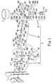
- Fig. 1 illustrates an assembly view of an automatic cooking device in accordance with a prefer example of the present invention.
- the present invention provides an automatic cooking device with an embedded control for regulating cooking process, wherein the automatic cooking device comprises a fixed structure 1 with four fixed bars 11-14.
- the fixed bars such as 11 and 12, are arranged vertically, and the fixed bars 13 and 14 can be arranged horizontally to the fixed bars 11 and 12 as shown in Figs 2 and 3 , but other arrangements between the fixed bars 11-14 can be laid, such as the fixed bars 13 and 14 are arranged at a slant angle to the fixed bars 11 and 12, or perpendicularly to each other to form a square-shaped structure. Accordingly, the arrangements between the fixed bars 11-14 are not limited or restricted to the above-mentioned arrangements.
- the automatic cooking device further comprises a rotating body 3 and a cooking vessel 5, wherein the rotating body 3 is utilized to integrate with the cooking vessel 5 with the fixed structure 1 by mounting the cooking vessel 5 onto a top portion of the rotating body 3 to perform 3-dimensional motion, the movement of the automatic device includes vibration, expanding and contracting motions, rotating, swinging or a combination of any two different motions.
- the rotating body 3 comprises a first rotating device 31 attaching onto the fixed structure 1, a first fixed device 33 and a second rotating device 35.
- the first rotating device 31 further comprises a first driving motor 311, a plurality of attaching rings 312, 313, 314 and 315, and a plurality of attaching plates, wherein the attaching plates include an attaching plate 316, an upper plate 317, a right plate 318, a bottom plate 319 and a left plate 320.
- the first device 33 is connected to an opposite side to a connection between the first rotating device 31 and the fixed bars 11-14 of the fixed structure 1 in such that the first device 33 is driven by the first rotating device to rotate and vibrate.
- the first device 33 comprises a first connecting unit 331 and a plurality of fixed units, wherein the fixed units further divided into an upper fixed unit 332, a right fixed unit 333 and a left fixed unit 334.
- a plurality of fixed plates, such as a fixed plate 338, a front fixed plate 335 and a rear fixed plate 336, are provided to integrate with the fixed units 332-334, wherein an integrating unit 337, such as a gear shifting box, is provided to interact with the first driving motor 311.
- a second rotating device 35 is provided to integrate with the first device 33 and the first rotating device 31 on the fixed structure1, wherein the second rotating device 35 comprises a second connecting unit 351, a plurality of fixed units 352-355 such as screws, a plurality of fixed plates 356 and 369, an O-ring unit 357, and a plurality of connecting rings 358 and 363.
- a second driving motor 359, a plurality of bearings 360 and 362, a plurality of caps 361 and 364, and a plurality of fixed units such as screws 365-368 are also provided in the second rotating device 35.
- a third rotating device 37 is utilized to position the cooking vessel 5 with the second rotating device 35 and the first device 33 such that the third rotating device 37 can move or rotate corresponding to the second rotating device 35.
- the third rotating device 37 comprises a plurality of fixed units, such as screws 371-374, 382,386-387, 389 and 393 -394, a third driving motor 375, a connecting plate 380, a plurality of screw caps 376-379,383, 389,390, 395-398, a plurality of connecting plates 381 and 388, a plurality of O-ring units 384, 385, 391 and 392, and a plurality of sleeves 386'. 387', 393', 394' and 399.
- the cooking vessel 5 is positioned on the third rotating device 37 in such that the cooking vessel is rotated corresponding to the movement of the combination between the second rotating device 35 and the first device 33.
- Fig. 2 illustrates a 3-D view of the assembled automatic cooking device in accordance with a preferred example of the present invention.
- the cooking vessel 5 is integrated with the rotating body 3 and the fixed structure 1.
- Fig. 3 shows a front-view to demonstrate how the assembled automatic cooking device can be operated in accordance with a preferred example of the present invention.
- the first device 33 of the rotating body 3 rotates along a central axis D-D' of the automatic cooking device.
- the first device 33 of the rotating body 3 swings along a direction A in such that the second rotating device 35 of the rotating body 3 is interacted with the first rotating device 31 and the first device 33 to move along the direction A.
- the third rotating device 37 swings along a direction B as shown in Fig. 3 so that the third rotating device 37 of the rotating body 3 is interacted with the second rotating device 35.
- the cooking vessel 5 is then rotated in a rotation direction C in such that the ingredients within the cooking vessel can be mixed up and heated up or cooked up through a heater 7.
- the automatic cooking device of the present invention is designed in such to manage complex cooking processes or food preparation, the food can be prepared either through hot oil, such as stir-fry, or hot air or steam.
- the automatic cooking device of the present invention utilizes a computerized cooking program to control and manage various temperatures and different cooking time settings for different types of food, therefore, the ingredients are properly controlled through the cooking program in order to provide consistent flavor and good quality taste of food. Further, the amount of the food to be prepared can be controlled actuarially through the automatic cooking device, thus it is simple to operate and control without requiring specific skill or knowledge.
- the automatic cooking device that is cost effective can be moved and transported easily form place to place. Thus, it can be operated by most of people without much difficulty.
- the present invention can be utilized with computer program to regulate and control the cooking processes of the food, and store the data of the particular taste and flavor of every meal.
- the data base of the computerized program can record the information of specific meals with particular ingredients for particular customer, when the consumer go to one of food-chain restaurants utilizing the automatic cooking device, he or she still can get the specific flavor and taste of the meals no matter where she or he is.
- the automatic cooking device can be incorporated with computer and Internet service such that customers can order their favor food with exact quality of taste easily from their own homes.
Landscapes
- Engineering & Computer Science (AREA)
- Food Science & Technology (AREA)
- Mechanical Engineering (AREA)
- Food-Manufacturing Devices (AREA)
- Cookers (AREA)
Claims (8)
- Eine automatische Kochvorrichtung, umfassend
eine befestigte Struktur (1) mit mindestens einem befestigten Balken (11 - 14), während die Mehrzahl der befestigten Balken vertikal oder horizontal oder in einem schrägen Winkel angeordnet werden kann,
einen Drehkörper (3), der eine erste Drehvorrichtung (31), eine erste Vorrichtung, eine zweite Drehvorrichtung (35) und eine dritte Drehvorrichtung (37) aufweist, während der Drehkörper (3) mit der befestigten Struktur (1) verbunden ist, um eine dreidimensionale Bewegung auszuführen, sowie
ein Kochgefäß (5), das auf einer Seite mit dem Drehkörper (3) verbunden ist, während eine andere Seite des Drehkörpers (3) mit der befestigten Struktur (1) so verbunden ist, dass der Drehkörper (3) einen Betrieb des Kochgefäßes (5) mit der dreidimensionalen Bewegung veranlasst, während ein erster Antriebsmotor (311) bereitgestellt ist an einem Ende der ersten Drehvorrichtung (31), die mit der befestigten Struktur (1) verbunden ist, die erste Vorrichtung (33) ist mit einer Seite der ersten Drehvorrichtung (31) verbunden, während die entgegengesetzte Seite der ersten Drehvorrichtung (31) mit der befestigten Struktur (1) verbunden ist, so dass die erste Vorrichtung (33) durch den ersten Antriebsmotor (311) zum Schwingen angetrieben wird, die zweite Drehvorrichtung (3 5) ist mit einer Seite der ersten Vorrichtung (33) verbunden, um mit der ersten Vorrichtung (33) zu interagieren, während die dritte Vorrichtung (37) an einer Seite der zweiten Drehvorrichtung (35) angeordnet ist, die entgegengesetzt der Verbindungsseite der zweiten Drehvorrichtung (35) mit der ersten Vorrichtung (33) ist, um mit der zweiten Drehvorrichtung (35) zu interagieren. - Die automatische Kochvorrichtung gemäß Anspruch 1, in der die erste Drehvorrichtung (31) weiterhin eine Mehrzahl an Befestigungsringen (312 - 315) und eine Mehrzahl an Befestigungsplatten (316 - 320) aufweist.
- Die automatische Kochvorrichtung gemäß Anspruch 1, in der eine erste Verbindungseinheit (331), mindestens eine integrierende Einheit (337), eine Mehrzahl an befestigten Einheiten (332 - 334) sowie befestigten Platten (338, 335, 336) vorhanden ist.
- Die automatische Kochvorrichtung gemäß Anspruch 1, in der die zweite Drehvorrichtung (35) weiterhin eine zweite Verbindungseinheit (351) aufweist, eine Mehrzahl befestigter Einheiten (352 - 355), wie beispielsweise Schrauben, eine Mehrzahl befestigter Platten (356, 369), mindestens eine O-Ringeinheit (357) und eine Mehrzahl an Verbindungsringen (358), einen zweiten Antriebsmotor (359), eine Mehrzahl an Lagern (360, 362), eine Mehrzahl an Kappen (361, 364) und eine Mehrzahl an befestigten Einheiten, wie beispielsweise Schrauben (365 - 368).
- Die automatische Kochvorrichtung gemäß Anspruch 1, in der die dritte Drehvorrichtung (37) eine Mehrzahl befestigter Einheiten umfasst, wie beispielsweise Schrauben (371-374, 382, 386 - 387), einen dritten Antriebsmotor (375), mindestens eine Verbindungsplatte (380), eine Mehrzahl an Schraubenkappen (376 - 379, 383, 389, 390, 395 - 398), eine Mehrzahl an Verbindungsplatten (381, 388), eine Mehrzahl an O-Ringeinheiten (384, 385, 391, 392) sowie eine Mehrzahl an Muffen (386', 387', 393 394', 399).
- Die automatische Kochvorrichtung gemäß Anspruch 1, in der die dreidimensionale Bewegung umfassen kann: Rotation, Vibration, Ausstreck- und Zusammenziehbewegungen, Schwingen oder irgendeine dieser Bewegungen.
- Die automatische Kochvorrichtung gemäß Anspruch 1, in der die dreidimensionale Bewegung umfasst: Rotation, Vibration, Ausstreck- und Zusammenziehbewegungen, Schwingen oder irgendwelche zwei dieser Bewegungen.
- Die automatische Kochvorrichtung gemäß Anspruch 1, in der die dreidimensionale Bewegung umfasst: Rotation, Vibration, Ausstreck- und Zusammenziehbewegungen, Schwingen oder eine Kombination von irgendwelchen zweien dieser Bewegungen gleichzeitig.
Priority Applications (2)
| Application Number | Priority Date | Filing Date | Title |
|---|---|---|---|
| DE200660013144 DE602006013144D1 (de) | 2006-10-06 | 2006-10-06 | Automatische Kochvorrichtung |
| EP20060021054 EP1908381B1 (de) | 2006-10-06 | 2006-10-06 | Automatische Kochvorrichtung |
Applications Claiming Priority (1)
| Application Number | Priority Date | Filing Date | Title |
|---|---|---|---|
| EP20060021054 EP1908381B1 (de) | 2006-10-06 | 2006-10-06 | Automatische Kochvorrichtung |
Publications (2)
| Publication Number | Publication Date |
|---|---|
| EP1908381A1 EP1908381A1 (de) | 2008-04-09 |
| EP1908381B1 true EP1908381B1 (de) | 2010-03-24 |
Family
ID=37768737
Family Applications (1)
| Application Number | Title | Priority Date | Filing Date |
|---|---|---|---|
| EP20060021054 Not-in-force EP1908381B1 (de) | 2006-10-06 | 2006-10-06 | Automatische Kochvorrichtung |
Country Status (2)
| Country | Link |
|---|---|
| EP (1) | EP1908381B1 (de) |
| DE (1) | DE602006013144D1 (de) |
Families Citing this family (1)
| Publication number | Priority date | Publication date | Assignee | Title |
|---|---|---|---|---|
| CN103027595B (zh) * | 2012-12-29 | 2015-04-15 | 黑龙江省发现者厨房机器人科技有限公司 | 一种烹调机器用自动翻炒机构 |
Family Cites Families (2)
| Publication number | Priority date | Publication date | Assignee | Title |
|---|---|---|---|---|
| CH451443A (de) * | 1966-02-04 | 1968-05-15 | Andre Leon | Einrichtung zum Zubereiten von Zutaten enthaltenden Speisen |
| WO2003096853A1 (en) * | 2002-05-16 | 2003-11-27 | Joseph Clark Ryley | A machine and method for treating edible material |
-
2006
- 2006-10-06 DE DE200660013144 patent/DE602006013144D1/de active Active
- 2006-10-06 EP EP20060021054 patent/EP1908381B1/de not_active Not-in-force
Also Published As
| Publication number | Publication date |
|---|---|
| EP1908381A1 (de) | 2008-04-09 |
| DE602006013144D1 (de) | 2010-05-06 |
Similar Documents
| Publication | Publication Date | Title |
|---|---|---|
| US7485830B2 (en) | Automatic cooking device | |
| US12137835B1 (en) | Automatic cooking machine having a blocking element for magnetically attaching on a moving arm | |
| JP6062540B2 (ja) | 調理装置、調理用鍋、および調理方法 | |
| CN101125064B (zh) | 垂直和水平烤箱 | |
| WO2015075730A2 (en) | Portable fully automatic cooking system | |
| CN103239122A (zh) | 一种自动炒菜机 | |
| DE102009000652A1 (de) | Portable medienfähige Konsole | |
| CN203263042U (zh) | 一种自动炒菜机 | |
| US20230098024A1 (en) | Cooking robot system and method | |
| DE102015103380A1 (de) | Verfahren und System mit einer Steuerung für die Zubereitung von Speisen | |
| EP3434981A1 (de) | Knopfanordnung und gerät damit | |
| EP1908381B1 (de) | Automatische Kochvorrichtung | |
| CN207492550U (zh) | 烹饪器具 | |
| AU2006203478A1 (en) | Food processor | |
| EP3627276B1 (de) | Gelenk- und knopfanordnung und gerät mit gelenk- und knopfanordnung | |
| CN212995982U (zh) | 倾斜式自动炒菜机 | |
| CN112971512B (zh) | 包括搅拌叶片的用于烹饪食物的电烹饪器具 | |
| CN108926225A (zh) | 烹饪器具及胶囊运动的控制方法 | |
| JP7565702B2 (ja) | レシピ提供方法、プログラム及び情報端末 | |
| CN209992871U (zh) | 温控装置及应用其的烹饪电器 | |
| CN208988497U (zh) | 多餐盒式食物加热熟化装置 | |
| CN215127526U (zh) | 控制组件及烹饪器具 | |
| CN214157093U (zh) | 一种操作便捷的煎烤机 | |
| WO2025220253A1 (ja) | 自動調理装置 | |
| CN207370505U (zh) | 锅具和早餐机 |
Legal Events
| Date | Code | Title | Description |
|---|---|---|---|
| PUAI | Public reference made under article 153(3) epc to a published international application that has entered the european phase |
Free format text: ORIGINAL CODE: 0009012 |
|
| AK | Designated contracting states |
Kind code of ref document: A1 Designated state(s): AT BE BG CH CY CZ DE DK EE ES FI FR GB GR HU IE IS IT LI LT LU LV MC NL PL PT RO SE SI SK TR |
|
| AX | Request for extension of the european patent |
Extension state: AL BA HR MK RS |
|
| 17P | Request for examination filed |
Effective date: 20081009 |
|
| AKX | Designation fees paid |
Designated state(s): DE FR GB |
|
| GRAP | Despatch of communication of intention to grant a patent |
Free format text: ORIGINAL CODE: EPIDOSNIGR1 |
|
| GRAS | Grant fee paid |
Free format text: ORIGINAL CODE: EPIDOSNIGR3 |
|
| GRAA | (expected) grant |
Free format text: ORIGINAL CODE: 0009210 |
|
| AK | Designated contracting states |
Kind code of ref document: B1 Designated state(s): DE FR GB |
|
| REG | Reference to a national code |
Ref country code: GB Ref legal event code: FG4D |
|
| REF | Corresponds to: |
Ref document number: 602006013144 Country of ref document: DE Date of ref document: 20100506 Kind code of ref document: P |
|
| PLBE | No opposition filed within time limit |
Free format text: ORIGINAL CODE: 0009261 |
|
| STAA | Information on the status of an ep patent application or granted ep patent |
Free format text: STATUS: NO OPPOSITION FILED WITHIN TIME LIMIT |
|
| PGFP | Annual fee paid to national office [announced via postgrant information from national office to epo] |
Ref country code: DE Payment date: 20101029 Year of fee payment: 5 |
|
| 26N | No opposition filed |
Effective date: 20101228 |
|
| PGFP | Annual fee paid to national office [announced via postgrant information from national office to epo] |
Ref country code: GB Payment date: 20101001 Year of fee payment: 5 |
|
| PGFP | Annual fee paid to national office [announced via postgrant information from national office to epo] |
Ref country code: FR Payment date: 20111103 Year of fee payment: 6 |
|
| GBPC | Gb: european patent ceased through non-payment of renewal fee |
Effective date: 20121006 |
|
| REG | Reference to a national code |
Ref country code: FR Ref legal event code: ST Effective date: 20130628 |
|
| PG25 | Lapsed in a contracting state [announced via postgrant information from national office to epo] |
Ref country code: DE Free format text: LAPSE BECAUSE OF NON-PAYMENT OF DUE FEES Effective date: 20130501 Ref country code: GB Free format text: LAPSE BECAUSE OF NON-PAYMENT OF DUE FEES Effective date: 20121006 |
|
| REG | Reference to a national code |
Ref country code: DE Ref legal event code: R119 Ref document number: 602006013144 Country of ref document: DE Effective date: 20130501 |
|
| PG25 | Lapsed in a contracting state [announced via postgrant information from national office to epo] |
Ref country code: FR Free format text: LAPSE BECAUSE OF NON-PAYMENT OF DUE FEES Effective date: 20121031 |