EP1908532B1 - Flexible air extraction system - Google Patents
Flexible air extraction system Download PDFInfo
- Publication number
- EP1908532B1 EP1908532B1 EP07018693A EP07018693A EP1908532B1 EP 1908532 B1 EP1908532 B1 EP 1908532B1 EP 07018693 A EP07018693 A EP 07018693A EP 07018693 A EP07018693 A EP 07018693A EP 1908532 B1 EP1908532 B1 EP 1908532B1
- Authority
- EP
- European Patent Office
- Prior art keywords
- nozzles
- air
- hoses
- nozzle
- flanges
- Prior art date
- Legal status (The legal status is an assumption and is not a legal conclusion. Google has not performed a legal analysis and makes no representation as to the accuracy of the status listed.)
- Active
Links
Images


Classifications
-
- B—PERFORMING OPERATIONS; TRANSPORTING
- B08—CLEANING
- B08B—CLEANING IN GENERAL; PREVENTION OF FOULING IN GENERAL
- B08B15/00—Preventing escape of dirt or fumes from the area where they are produced; Collecting or removing dirt or fumes from that area
- B08B15/02—Preventing escape of dirt or fumes from the area where they are produced; Collecting or removing dirt or fumes from that area using chambers or hoods covering the area
-
- B—PERFORMING OPERATIONS; TRANSPORTING
- B08—CLEANING
- B08B—CLEANING IN GENERAL; PREVENTION OF FOULING IN GENERAL
- B08B15/00—Preventing escape of dirt or fumes from the area where they are produced; Collecting or removing dirt or fumes from that area
- B08B15/002—Preventing escape of dirt or fumes from the area where they are produced; Collecting or removing dirt or fumes from that area using a central suction system, e.g. for collecting exhaust gases in workshops
-
- B—PERFORMING OPERATIONS; TRANSPORTING
- B08—CLEANING
- B08B—CLEANING IN GENERAL; PREVENTION OF FOULING IN GENERAL
- B08B15/00—Preventing escape of dirt or fumes from the area where they are produced; Collecting or removing dirt or fumes from that area
- B08B15/007—Fume suction nozzles arranged on a closed or semi-closed surface, e.g. on a circular, ring-shaped or rectangular surface adjacent the area where fumes are produced
Definitions
- the invention relates to an air extraction and filtering system according to the preamble of claim 1.
- the case of a shipyard and, in particular, the construction of hulls in resin and their varnishing in other words, a working process which development varies from time to time in function of the dimensions of the hulls to varnish that necessarily have to be worked in the same space where a totally different processing has been done on other hulls.
- the shipyards use a system of scaffolds to wrap up the hull, in accordance with the specific case, either the whole hull or one of its sides, and eventually also the upper surface of the hull or a part of it, with plastic material, generally transparent, in order to create a tunnel like space that provides isolation between the working area where the varnishing process is being done and the surroundings.
- plastic material generally transparent
- the pavement where the hull is being placed is indicated as nr. (1), as nr. (2) the hull, the transparent wrapping of the upper part of the hull as nr. (3) and as nr. (4) the farthest part of the lateral transparent wrapping realized on a scaffold construction. Both wrappings are an example of a tunnel like space in the shipbuilding industry.
- a known system such as the one disclosed in US6395047 , having the features of the preamble of the annexed independent claim, comprises a plurality of hose lines with end aspiration nozzles which can be put in different points of the working area.
- the adaptability of this system to the conformation of the working area is limited.
- the object of the present invention is to provide an air extraction and filtering system for extraction and filtration of toxic agents which makes possible the dislocation of the air intake units, that is the vapors and solvents intake units, in several points along the inside area of the tunnel and to put in activity one or more of these by simple operations also during the working process.
- This enables to shorten considerably the distance the air has to cross from the point where the vapors are generated to the point of air intake and to increase in considerable way the air speed inside the hoses in order to avoid this way, or at least to limit, the depositing of condensed vapors or powder.
- the invention consists of a component constituted by an aspiration nozzle, fitted in a way to have two ends, generally opposite, two flanges that enable a quick connection to hose elements that form a hose line for airflow, or in case of an eventual terminal nozzle, a final plug.
- the nozzle furthermore, is equipped with one or more closable openings, in general to be opened separately, that enable to conform the nozzle either as a flow through or as an air aspiration unit and in case of more openings present, to vary the air intake capacity of the nozzle.
- the nozzles may be equipped with more than one opening, as already mentioned, eventually to be closed separately, in order to choke the air flow of one specific nozzle part of the installation and enable, for example, the use of two neighboring nozzles choking the air flow of the nozzle closest to the aspiration point, avoiding in this way the air flow entering to concentrate exclusively on one nozzle and, more in general, to utilize optimally the potential of the aspirator, or of the aspirators, in function of the air intake units necessary .
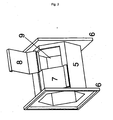
- the nozzles might be realized in metal or plastic material of a prism similar form on hexagonal basis see fig. 2 , the variation of form and constructive solution without going out of the invention.
- the nozzles might have, without going out of the invention, all the combinations in number of closable flaps.
- the flaps might be hinged up on one side to be opened and closed easily, remaining the possibility to use any solution, comprising rotation on an axis that enables a total or partial opening of a slit of semi circular form or a different one, or a system that enables the total removal of the flap, as stopper.
- nr. (5) there is the body of the aspiration nozzle, as nr. (6) the flanges for hose connection, as nr. (7) the flap for covering the opening in closure position, as nr. (8) the flap in open position and as nr. (9) the opening for air intake.
- the extremities of the nozzle might be usefully conformed by means of a connector in iron, in plastic material or any combination of materials and construction technique that makes possible the connection between the body of the nozzle and the hose conducting the air flow aspirated.
- a connection between the nozzle, as illustrated, and a conduct of circular section In particular, indicated as nr. (10) there is the flange attached to the hose that matches the flange on the aspiration nozzle and as nr. (11) the junction for the circular section hose. Indicated as nr. (12) there is the hose, in this specific case, flexible.
- the unit composed of the body of the nozzle, the flap/s and the flanges is named "aspiration nozzle”.
- Two or more nozzles connected together, attached to one or more aspirators by means of a hose line carrying air and varnish vapors conform the so called "modular air extraction and filtration system".
- connection between aspiration nozzles and the aspirator, or aspirators might be done, as pictured, by means of flexible hoses of circle section, without these being considered a limitation to the protection of this invention, making possible the use of other sections for the conduct and/or every combination of rigid, semi rigid or flexible material permitting the aspiration inside the tunnel or, however, in a narrow and long workspace.
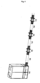
- fig. 4 a solution that makes possible the setting up of the installation according to the above described characteristics.
- fig. 4 indicated as nr. 13 there are the nozzles, as nr. 14 the hoses and as nr. 15 the aspirator placed on one extremity of the installation.
Landscapes
- Filtering Of Dispersed Particles In Gases (AREA)
- Absorbent Articles And Supports Therefor (AREA)
- Nozzles For Electric Vacuum Cleaners (AREA)
- Manipulator (AREA)
- Details Or Accessories Of Spraying Plant Or Apparatus (AREA)
- External Artificial Organs (AREA)
Abstract
Description
- The invention relates to an air extraction and filtering system according to the preamble of
claim 1. - At the actual state of art, there are, in certain and particular production fields, where some structures are constructed with materials containing resins or these are varnished, a substantially unresolved problem, with the consequence of considerable exposure of workers to substances released by the production processes inside the working area.
- In particular, the problem arises when the above described processes are to be done on vertical and/or horizontal surfaces of medium and big dimensions, on objects that are often of different form or dimension between one production cycle and the succeeding one. As example, without considering it as a limitation to the application of the invention, the case of a shipyard and, in particular, the construction of hulls in resin and their varnishing, in other words, a working process which development varies from time to time in function of the dimensions of the hulls to varnish that necessarily have to be worked in the same space where a totally different processing has been done on other hulls. At the moment, the shipyards use a system of scaffolds to wrap up the hull, in accordance with the specific case, either the whole hull or one of its sides, and eventually also the upper surface of the hull or a part of it, with plastic material, generally transparent, in order to create a tunnel like space that provides isolation between the working area where the varnishing process is being done and the surroundings. See
fig. 1 . In this scheme the pavement where the hull is being placed is indicated as nr. (1), as nr. (2) the hull, the transparent wrapping of the upper part of the hull as nr. (3) and as nr. (4) the farthest part of the lateral transparent wrapping realized on a scaffold construction. Both wrappings are an example of a tunnel like space in the shipbuilding industry. - In consideration of this procedure, it results obvious that such division of space leads to a high concentration of toxic agents inside the tunnel, deriving from resin and varnishing processes. On this purpose, because of no solutions available resolving this problem efficiently, generally, one or more air filtration systems are being installed on one side of the tunnel in order to create air circulation.
- All of the known solutions are characterized by leaving unresolved some problems arising during the resin and varnishing problems, such as:
- · Air speed created inside of the tunnel is too low and thus the varnish dispersed in the air tends to set down on surfaces, particularly on the horizontal ones;
- · The average distance that the air has to cross to get to the aspiration unit is long and therefore a huge quantity of varnish or vapors produced by resin remain hanging in the air, with consequent high exposition of workers to toxic agents, and, in case of varnishing, a deterioration of already varnished surfaces.
- A known system such as the one disclosed in
US6395047 , having the features of the preamble of the annexed independent claim, comprises a plurality of hose lines with end aspiration nozzles which can be put in different points of the working area. However, the adaptability of this system to the conformation of the working area is limited. - Accordingly, the object of the present invention is to provide an air extraction and filtering system for extraction and filtration of toxic agents which makes possible the dislocation of the air intake units, that is the vapors and solvents intake units, in several points along the inside area of the tunnel and to put in activity one or more of these by simple operations also during the working process. This enables to shorten considerably the distance the air has to cross from the point where the vapors are generated to the point of air intake and to increase in considerable way the air speed inside the hoses in order to avoid this way, or at least to limit, the depositing of condensed vapors or powder.
- The above object is achieved according to the invention by the air extraction and filtering system as defined in
claim 1. Particular embodiments of the invention are the subject of the dependent claims. - Substantially, we are going to set up a movable and modular air filtering system, a detailed description will follow, suitable for aspiration of vapors or solvents, both from resin and varnishing processes. It consist of air intake nozzles, also these to be described into detail subsequently, equipped with specific openings for choking the air flow, using special hoses, generally flexible or however adaptable to the area to enable the dislocation of the nozzles on a certain distance one from the other either along the whole internal side of the tunnel or a part of it.
- The invention consists of a component constituted by an aspiration nozzle, fitted in a way to have two ends, generally opposite, two flanges that enable a quick connection to hose elements that form a hose line for airflow, or in case of an eventual terminal nozzle, a final plug. The nozzle furthermore, is equipped with one or more closable openings, in general to be opened separately, that enable to conform the nozzle either as a flow through or as an air aspiration unit and in case of more openings present, to vary the air intake capacity of the nozzle.
- Therefore, it is possible to set up a modular installation with several possible compositions of nozzles and hoses. This way it is possible to adapt the hose line to any kind of tunnel conformation, enabling the use of an air filtering unit on one end of the hose line or alternatively, of two air filters, placed on both extremities of the tunnel.
- The nozzles may be equipped with more than one opening, as already mentioned, eventually to be closed separately, in order to choke the air flow of one specific nozzle part of the installation and enable, for example, the use of two neighboring nozzles choking the air flow of the nozzle closest to the aspiration point, avoiding in this way the air flow entering to concentrate exclusively on one nozzle and, more in general, to utilize optimally the potential of the aspirator, or of the aspirators, in function of the air intake units necessary .
- The nozzles might be realized in metal or plastic material of a prism similar form on hexagonal basis see
fig. 2 , the variation of form and constructive solution without going out of the invention. - The nozzles might have, without going out of the invention, all the combinations in number of closable flaps.
- The flaps might be hinged up on one side to be opened and closed easily, remaining the possibility to use any solution, comprising rotation on an axis that enables a total or partial opening of a slit of semi circular form or a different one, or a system that enables the total removal of the flap, as stopper.
- In particular, in
fig. 2 , indicated as nr. (5) there is the body of the aspiration nozzle, as nr. (6) the flanges for hose connection, as nr. (7) the flap for covering the opening in closure position, as nr. (8) the flap in open position and as nr. (9) the opening for air intake. - The extremities of the nozzle might be usefully conformed by means of a connector in iron, in plastic material or any combination of materials and construction technique that makes possible the connection between the body of the nozzle and the hose conducting the air flow aspirated. On
fig. 3 , for example, neither exclusive nor limiting, there is a possible solution of a connection between the nozzle, as illustrated, and a conduct of circular section. In particular, indicated as nr. (10) there is the flange attached to the hose that matches the flange on the aspiration nozzle and as nr. (11) the junction for the circular section hose. Indicated as nr. (12) there is the hose, in this specific case, flexible. - The unit composed of the body of the nozzle, the flap/s and the flanges is named "aspiration nozzle".
- Two or more nozzles connected together, attached to one or more aspirators by means of a hose line carrying air and varnish vapors conform the so called "modular air extraction and filtration system".
- The connection between aspiration nozzles and the aspirator, or aspirators, might be done, as pictured, by means of flexible hoses of circle section, without these being considered a limitation to the protection of this invention, making possible the use of other sections for the conduct and/or every combination of rigid, semi rigid or flexible material permitting the aspiration inside the tunnel or, however, in a narrow and long workspace.
- As example without exclusivity or limitation, on
fig. 4 , a solution that makes possible the setting up of the installation according to the above described characteristics. Infig. 4 , indicated as nr. 13 there are the nozzles, as nr. 14 the hoses and as nr. 15 the aspirator placed on one extremity of the installation.
Claims (9)
- An air extraction and filtering system for extraction and filtration of toxic agents such as solvents, resins or varnishing vapors deriving from varnishing or resin application processes carried out in a working area, the system comprising aspirator means (15), a plurality of nozzles (13) with one or more closable openings, and fitted hoses (14) for connecting together said nozzles (13), characterized in that said nozzles and hoses are defined by respective modular elements with flanges (6;10) enabling a quick connection for composing at least one hose line, whereby the development of said line or lines and the number and position of the nozzles (13) is adaptable to the conformation of said working area and to the points where said toxic agents are generated.
- The system according to claim 1, wherein each of said nozzles (13) comprises two or more openings (9) to be closed separately.
- The system according to claim 1 or 2, wherein each of said nozzle comprises two or more flaps (7,8) for closure of said air-intake opening (9).
- The system according to any of the previous claims, wherein each of said nozzles composes a body (5) with two axial ends, generally opposite, two flanges (6) at respective ends of said body (5), for connection with respective of said hoses (14) or to a final plug, an air-intake opening (9) formed in said body (5), and two flaps (7, 8) hinged to said body (5) for closing said air-intake opening (9), to be opened separately for permitting to vary the air intake capacity of the nozzle (13).
- The system according to claim 4, wherein said body (5) has a prismatic shape, said opening (9) bering formed in a flat face of the body (5).
- The system according to claim 4 or 5, wherein each of said hose (14) comprises, at respective axial ends, flanges (10) for quick connection with said flanges (6) of said nozzle (13).
- The system according to any of the previous claims, wherein at least one of said nozzles (13) comprises at least one device for choking the airflow.
- The system according to any of the previous claims, wherein said hoses (14) are flexible.
- The system according to any of the previous claims, in which said working area is defined by a wrapping tunnel, scaffolds or another kind of segregation system.
Applications Claiming Priority (1)
| Application Number | Priority Date | Filing Date | Title |
|---|---|---|---|
| IT000009A ITPO20060009A1 (en) | 2006-10-02 | 2006-10-02 | LOCALIZED, MODULAR AND MODULAR SUCTION SYSTEM EQUIPPED WITH OPENABLE OR PARTIALIZABLE NOZZLES |
Publications (2)
| Publication Number | Publication Date |
|---|---|
| EP1908532A1 EP1908532A1 (en) | 2008-04-09 |
| EP1908532B1 true EP1908532B1 (en) | 2010-07-07 |
Family
ID=38922452
Family Applications (1)
| Application Number | Title | Priority Date | Filing Date |
|---|---|---|---|
| EP07018693A Active EP1908532B1 (en) | 2006-10-02 | 2007-09-24 | Flexible air extraction system |
Country Status (5)
| Country | Link |
|---|---|
| EP (1) | EP1908532B1 (en) |
| AT (1) | ATE473060T1 (en) |
| DE (1) | DE602007007555D1 (en) |
| ES (1) | ES2348185T3 (en) |
| IT (1) | ITPO20060009A1 (en) |
Family Cites Families (8)
| Publication number | Priority date | Publication date | Assignee | Title |
|---|---|---|---|---|
| AT259822B (en) * | 1965-04-22 | 1968-02-12 | Schwarz Walter | Ventilation system |
| DE29620172U1 (en) * | 1996-11-20 | 1997-02-27 | Kramer & Best Anlagenbau GmbH, 56281 Dörth | Flour dedusting system |
| DE19920058A1 (en) * | 1999-05-03 | 2000-11-09 | Esta Apparatebau | Device especially for drawing out dust-laden crude gas has auxiliary gas inlet connected to main pipe and with opening cross section variable depending upon throughflow of main pipe |
| DE10106672B4 (en) * | 2001-02-14 | 2004-03-18 | Koenig & Bauer Ag | Slitter |
| US6395047B1 (en) * | 2001-02-16 | 2002-05-28 | William C. Smith | Portable airborne contamination control system including a main and remote unit |
| US6669547B2 (en) * | 2001-08-28 | 2003-12-30 | Board Of Regents Of University Of Nebraska | Multi-stack exhaust system |
| DE10234637B4 (en) * | 2002-07-29 | 2013-10-17 | DüRR DENTAL AG | Suction unit for dental use |
| US20060154595A1 (en) * | 2005-01-06 | 2006-07-13 | International Business Machines Corporation | Static pressure stabilizer for local exhaust |
-
2006
- 2006-10-02 IT IT000009A patent/ITPO20060009A1/en unknown
-
2007
- 2007-09-24 AT AT07018693T patent/ATE473060T1/en not_active IP Right Cessation
- 2007-09-24 ES ES07018693T patent/ES2348185T3/en active Active
- 2007-09-24 EP EP07018693A patent/EP1908532B1/en active Active
- 2007-09-24 DE DE602007007555T patent/DE602007007555D1/en active Active
Also Published As
| Publication number | Publication date |
|---|---|
| DE602007007555D1 (en) | 2010-08-19 |
| ATE473060T1 (en) | 2010-07-15 |
| ES2348185T3 (en) | 2010-12-01 |
| EP1908532A1 (en) | 2008-04-09 |
| ITPO20060009A1 (en) | 2008-04-03 |
Similar Documents
| Publication | Publication Date | Title |
|---|---|---|
| CN104185512B (en) | Method and device for extracting process air containing overspray and apparatus for coating objects | |
| CN207966923U (en) | Exhaust Devices for Wafer Handling Equipment | |
| EP2290298A3 (en) | Device for diverting an air flow, in particular for an extractor hood | |
| KR101884239B1 (en) | Movable poisonous gas reducing apparatus | |
| ITRE20120007A1 (en) | FILTERING CARTRIDGE | |
| EP1908532A1 (en) | Flexible air extraction system | |
| JP6982187B2 (en) | Spray assembly and agricultural plant protector | |
| CN103381412A (en) | Dust removing device | |
| CN113198662B (en) | Environment-friendly spraying device for anti-corrosion pipeline | |
| KR20090111902A (en) | Water purifier filter assembly device and method | |
| CN205710989U (en) | A kind of drying integrated auto parts machinery electrophoretic paint datatron capable of washing | |
| CN209967973U (en) | Waste gas purification device for paint spraying part drying workshop | |
| CA2403734A1 (en) | Cabinets for handling toxic or sterile materials | |
| CN202555553U (en) | Dust removing device | |
| CN104436933A (en) | Water type dust removal device | |
| CN115970949A (en) | Dry paint spraying chamber | |
| CN210079236U (en) | Flue gas desulfurization denitration processing apparatus | |
| CN209773016U (en) | Self-cleaning type fume chamber | |
| KR101173438B1 (en) | Multi-hood local exhaust ventilation method for air pollution sources having emission fluctuation and ventilation Apparatus using the said method | |
| KR101884240B1 (en) | Movable poisonous gas reducing apparatus with improved efficiency | |
| CN208178384U (en) | Pernicious gas removal device and cold core core making machine | |
| CN207137601U (en) | A kind of compounding machine drying tunnel with filter | |
| CN210413898U (en) | Grinding wheel cooling device of glass edge grinding machine | |
| CN109173467A (en) | A kind of dust treatment integrated apparatus | |
| CN221602336U (en) | Paint mist recycling equipment for spraying device |
Legal Events
| Date | Code | Title | Description |
|---|---|---|---|
| PUAI | Public reference made under article 153(3) epc to a published international application that has entered the european phase |
Free format text: ORIGINAL CODE: 0009012 |
|
| AK | Designated contracting states |
Kind code of ref document: A1 Designated state(s): AT BE BG CH CY CZ DE DK EE ES FI FR GB GR HU IE IS IT LI LT LU LV MC MT NL PL PT RO SE SI SK TR |
|
| AX | Request for extension of the european patent |
Extension state: AL BA HR MK RS |
|
| RIN1 | Information on inventor provided before grant (corrected) |
Inventor name: GHILARDI, GIANLUIGI Inventor name: CARRAI, CARLO ALBERTO Inventor name: BERTACCA, ALESSANDRO |
|
| RIN1 | Information on inventor provided before grant (corrected) |
Inventor name: BERTACCA, ALESSANDRO Inventor name: GHILARDI, GIANLUIGI Inventor name: CARRAI, CARLO ALBERTO |
|
| 17P | Request for examination filed |
Effective date: 20081007 |
|
| AKX | Designation fees paid |
Designated state(s): AT BE BG CH CY CZ DE DK EE ES FI FR GB GR HU IE IS IT LI LT LU LV MC MT NL PL PT RO SE SI SK TR |
|
| 17Q | First examination report despatched |
Effective date: 20090302 |
|
| GRAP | Despatch of communication of intention to grant a patent |
Free format text: ORIGINAL CODE: EPIDOSNIGR1 |
|
| GRAS | Grant fee paid |
Free format text: ORIGINAL CODE: EPIDOSNIGR3 |
|
| GRAA | (expected) grant |
Free format text: ORIGINAL CODE: 0009210 |
|
| AK | Designated contracting states |
Kind code of ref document: B1 Designated state(s): AT BE BG CH CY CZ DE DK EE ES FI FR GB GR HU IE IS IT LI LT LU LV MC MT NL PL PT RO SE SI SK TR |
|
| REG | Reference to a national code |
Ref country code: GB Ref legal event code: FG4D |
|
| REG | Reference to a national code |
Ref country code: CH Ref legal event code: EP |
|
| REG | Reference to a national code |
Ref country code: IE Ref legal event code: FG4D |
|
| REF | Corresponds to: |
Ref document number: 602007007555 Country of ref document: DE Date of ref document: 20100819 Kind code of ref document: P |
|
| REG | Reference to a national code |
Ref country code: NL Ref legal event code: T3 |
|
| PG25 | Lapsed in a contracting state [announced via postgrant information from national office to epo] |
Ref country code: SI Free format text: LAPSE BECAUSE OF FAILURE TO SUBMIT A TRANSLATION OF THE DESCRIPTION OR TO PAY THE FEE WITHIN THE PRESCRIBED TIME-LIMIT Effective date: 20100707 |
|
| LTIE | Lt: invalidation of european patent or patent extension |
Effective date: 20100707 |
|
| PG25 | Lapsed in a contracting state [announced via postgrant information from national office to epo] |
Ref country code: FI Free format text: LAPSE BECAUSE OF FAILURE TO SUBMIT A TRANSLATION OF THE DESCRIPTION OR TO PAY THE FEE WITHIN THE PRESCRIBED TIME-LIMIT Effective date: 20100707 Ref country code: AT Free format text: LAPSE BECAUSE OF FAILURE TO SUBMIT A TRANSLATION OF THE DESCRIPTION OR TO PAY THE FEE WITHIN THE PRESCRIBED TIME-LIMIT Effective date: 20100707 Ref country code: LT Free format text: LAPSE BECAUSE OF FAILURE TO SUBMIT A TRANSLATION OF THE DESCRIPTION OR TO PAY THE FEE WITHIN THE PRESCRIBED TIME-LIMIT Effective date: 20100707 |
|
| PG25 | Lapsed in a contracting state [announced via postgrant information from national office to epo] |
Ref country code: PL Free format text: LAPSE BECAUSE OF FAILURE TO SUBMIT A TRANSLATION OF THE DESCRIPTION OR TO PAY THE FEE WITHIN THE PRESCRIBED TIME-LIMIT Effective date: 20100707 Ref country code: IS Free format text: LAPSE BECAUSE OF FAILURE TO SUBMIT A TRANSLATION OF THE DESCRIPTION OR TO PAY THE FEE WITHIN THE PRESCRIBED TIME-LIMIT Effective date: 20101107 Ref country code: CY Free format text: LAPSE BECAUSE OF FAILURE TO SUBMIT A TRANSLATION OF THE DESCRIPTION OR TO PAY THE FEE WITHIN THE PRESCRIBED TIME-LIMIT Effective date: 20100707 Ref country code: BG Free format text: LAPSE BECAUSE OF FAILURE TO SUBMIT A TRANSLATION OF THE DESCRIPTION OR TO PAY THE FEE WITHIN THE PRESCRIBED TIME-LIMIT Effective date: 20101007 Ref country code: PT Free format text: LAPSE BECAUSE OF FAILURE TO SUBMIT A TRANSLATION OF THE DESCRIPTION OR TO PAY THE FEE WITHIN THE PRESCRIBED TIME-LIMIT Effective date: 20101108 |
|
| PG25 | Lapsed in a contracting state [announced via postgrant information from national office to epo] |
Ref country code: GR Free format text: LAPSE BECAUSE OF FAILURE TO SUBMIT A TRANSLATION OF THE DESCRIPTION OR TO PAY THE FEE WITHIN THE PRESCRIBED TIME-LIMIT Effective date: 20101008 Ref country code: BE Free format text: LAPSE BECAUSE OF FAILURE TO SUBMIT A TRANSLATION OF THE DESCRIPTION OR TO PAY THE FEE WITHIN THE PRESCRIBED TIME-LIMIT Effective date: 20100707 Ref country code: LV Free format text: LAPSE BECAUSE OF FAILURE TO SUBMIT A TRANSLATION OF THE DESCRIPTION OR TO PAY THE FEE WITHIN THE PRESCRIBED TIME-LIMIT Effective date: 20100707 Ref country code: SE Free format text: LAPSE BECAUSE OF FAILURE TO SUBMIT A TRANSLATION OF THE DESCRIPTION OR TO PAY THE FEE WITHIN THE PRESCRIBED TIME-LIMIT Effective date: 20100707 |
|
| PG25 | Lapsed in a contracting state [announced via postgrant information from national office to epo] |
Ref country code: MC Free format text: LAPSE BECAUSE OF NON-PAYMENT OF DUE FEES Effective date: 20100930 Ref country code: DK Free format text: LAPSE BECAUSE OF FAILURE TO SUBMIT A TRANSLATION OF THE DESCRIPTION OR TO PAY THE FEE WITHIN THE PRESCRIBED TIME-LIMIT Effective date: 20100707 |
|
| PLBE | No opposition filed within time limit |
Free format text: ORIGINAL CODE: 0009261 |
|
| STAA | Information on the status of an ep patent application or granted ep patent |
Free format text: STATUS: NO OPPOSITION FILED WITHIN TIME LIMIT |
|
| PG25 | Lapsed in a contracting state [announced via postgrant information from national office to epo] |
Ref country code: CZ Free format text: LAPSE BECAUSE OF FAILURE TO SUBMIT A TRANSLATION OF THE DESCRIPTION OR TO PAY THE FEE WITHIN THE PRESCRIBED TIME-LIMIT Effective date: 20100707 Ref country code: RO Free format text: LAPSE BECAUSE OF FAILURE TO SUBMIT A TRANSLATION OF THE DESCRIPTION OR TO PAY THE FEE WITHIN THE PRESCRIBED TIME-LIMIT Effective date: 20100707 Ref country code: IT Free format text: LAPSE BECAUSE OF NON-PAYMENT OF DUE FEES Effective date: 20100924 Ref country code: SK Free format text: LAPSE BECAUSE OF FAILURE TO SUBMIT A TRANSLATION OF THE DESCRIPTION OR TO PAY THE FEE WITHIN THE PRESCRIBED TIME-LIMIT Effective date: 20100707 Ref country code: EE Free format text: LAPSE BECAUSE OF FAILURE TO SUBMIT A TRANSLATION OF THE DESCRIPTION OR TO PAY THE FEE WITHIN THE PRESCRIBED TIME-LIMIT Effective date: 20100707 |
|
| 26N | No opposition filed |
Effective date: 20110408 |
|
| REG | Reference to a national code |
Ref country code: DE Ref legal event code: R097 Ref document number: 602007007555 Country of ref document: DE Effective date: 20110408 |
|
| PG25 | Lapsed in a contracting state [announced via postgrant information from national office to epo] |
Ref country code: IE Free format text: LAPSE BECAUSE OF NON-PAYMENT OF DUE FEES Effective date: 20100924 |
|
| PG25 | Lapsed in a contracting state [announced via postgrant information from national office to epo] |
Ref country code: MT Free format text: LAPSE BECAUSE OF FAILURE TO SUBMIT A TRANSLATION OF THE DESCRIPTION OR TO PAY THE FEE WITHIN THE PRESCRIBED TIME-LIMIT Effective date: 20100707 |
|
| REG | Reference to a national code |
Ref country code: CH Ref legal event code: PL |
|
| PG25 | Lapsed in a contracting state [announced via postgrant information from national office to epo] |
Ref country code: CH Free format text: LAPSE BECAUSE OF NON-PAYMENT OF DUE FEES Effective date: 20110930 Ref country code: LI Free format text: LAPSE BECAUSE OF NON-PAYMENT OF DUE FEES Effective date: 20110930 |
|
| PG25 | Lapsed in a contracting state [announced via postgrant information from national office to epo] |
Ref country code: LU Free format text: LAPSE BECAUSE OF NON-PAYMENT OF DUE FEES Effective date: 20100924 Ref country code: HU Free format text: LAPSE BECAUSE OF FAILURE TO SUBMIT A TRANSLATION OF THE DESCRIPTION OR TO PAY THE FEE WITHIN THE PRESCRIBED TIME-LIMIT Effective date: 20110108 |
|
| PG25 | Lapsed in a contracting state [announced via postgrant information from national office to epo] |
Ref country code: TR Free format text: LAPSE BECAUSE OF FAILURE TO SUBMIT A TRANSLATION OF THE DESCRIPTION OR TO PAY THE FEE WITHIN THE PRESCRIBED TIME-LIMIT Effective date: 20100707 |
|
| REG | Reference to a national code |
Ref country code: FR Ref legal event code: PLFP Year of fee payment: 10 |
|
| REG | Reference to a national code |
Ref country code: FR Ref legal event code: PLFP Year of fee payment: 11 |
|
| REG | Reference to a national code |
Ref country code: FR Ref legal event code: PLFP Year of fee payment: 12 |
|
| PGFP | Annual fee paid to national office [announced via postgrant information from national office to epo] |
Ref country code: NL Payment date: 20210920 Year of fee payment: 15 |
|
| PGFP | Annual fee paid to national office [announced via postgrant information from national office to epo] |
Ref country code: DE Payment date: 20210920 Year of fee payment: 15 |
|
| REG | Reference to a national code |
Ref country code: DE Ref legal event code: R119 Ref document number: 602007007555 Country of ref document: DE |
|
| REG | Reference to a national code |
Ref country code: NL Ref legal event code: MM Effective date: 20221001 |
|
| PG25 | Lapsed in a contracting state [announced via postgrant information from national office to epo] |
Ref country code: NL Free format text: LAPSE BECAUSE OF NON-PAYMENT OF DUE FEES Effective date: 20221001 |
|
| PG25 | Lapsed in a contracting state [announced via postgrant information from national office to epo] |
Ref country code: DE Free format text: LAPSE BECAUSE OF NON-PAYMENT OF DUE FEES Effective date: 20230401 |
|
| PGFP | Annual fee paid to national office [announced via postgrant information from national office to epo] |
Ref country code: IT Payment date: 20250910 Year of fee payment: 19 |
|
| PGFP | Annual fee paid to national office [announced via postgrant information from national office to epo] |
Ref country code: GB Payment date: 20250918 Year of fee payment: 19 |
|
| PGFP | Annual fee paid to national office [announced via postgrant information from national office to epo] |
Ref country code: FR Payment date: 20250919 Year of fee payment: 19 |
|
| PGFP | Annual fee paid to national office [announced via postgrant information from national office to epo] |
Ref country code: ES Payment date: 20251028 Year of fee payment: 19 |