EP1908546A1 - Diffuse laser beam reflector ; Room separation and working room with laser processing system with such a laser beam reflector - Google Patents
Diffuse laser beam reflector ; Room separation and working room with laser processing system with such a laser beam reflector Download PDFInfo
- Publication number
- EP1908546A1 EP1908546A1 EP06020907A EP06020907A EP1908546A1 EP 1908546 A1 EP1908546 A1 EP 1908546A1 EP 06020907 A EP06020907 A EP 06020907A EP 06020907 A EP06020907 A EP 06020907A EP 1908546 A1 EP1908546 A1 EP 1908546A1
- Authority
- EP
- European Patent Office
- Prior art keywords
- laser beam
- beam reflector
- working space
- laser
- reflector
- Prior art date
- Legal status (The legal status is an assumption and is not a legal conclusion. Google has not performed a legal analysis and makes no representation as to the accuracy of the status listed.)
- Ceased
Links
Images

Classifications
-
- B—PERFORMING OPERATIONS; TRANSPORTING
- B23—MACHINE TOOLS; METAL-WORKING NOT OTHERWISE PROVIDED FOR
- B23K—SOLDERING OR UNSOLDERING; WELDING; CLADDING OR PLATING BY SOLDERING OR WELDING; CUTTING BY APPLYING HEAT LOCALLY, e.g. FLAME CUTTING; WORKING BY LASER BEAM
- B23K26/00—Working by laser beam, e.g. welding, cutting or boring
- B23K26/12—Working by laser beam, e.g. welding, cutting or boring in a special environment or atmosphere, e.g. in an enclosure
- B23K26/127—Working by laser beam, e.g. welding, cutting or boring in a special environment or atmosphere, e.g. in an enclosure in an enclosure
-
- B—PERFORMING OPERATIONS; TRANSPORTING
- B23—MACHINE TOOLS; METAL-WORKING NOT OTHERWISE PROVIDED FOR
- B23K—SOLDERING OR UNSOLDERING; WELDING; CLADDING OR PLATING BY SOLDERING OR WELDING; CUTTING BY APPLYING HEAT LOCALLY, e.g. FLAME CUTTING; WORKING BY LASER BEAM
- B23K26/00—Working by laser beam, e.g. welding, cutting or boring
- B23K26/12—Working by laser beam, e.g. welding, cutting or boring in a special environment or atmosphere, e.g. in an enclosure
-
- B—PERFORMING OPERATIONS; TRANSPORTING
- B23—MACHINE TOOLS; METAL-WORKING NOT OTHERWISE PROVIDED FOR
- B23K—SOLDERING OR UNSOLDERING; WELDING; CLADDING OR PLATING BY SOLDERING OR WELDING; CUTTING BY APPLYING HEAT LOCALLY, e.g. FLAME CUTTING; WORKING BY LASER BEAM
- B23K26/00—Working by laser beam, e.g. welding, cutting or boring
- B23K26/20—Bonding
- B23K26/21—Bonding by welding
- B23K26/24—Seam welding
- B23K26/28—Seam welding of curved planar seams
-
- B—PERFORMING OPERATIONS; TRANSPORTING
- B23—MACHINE TOOLS; METAL-WORKING NOT OTHERWISE PROVIDED FOR
- B23K—SOLDERING OR UNSOLDERING; WELDING; CLADDING OR PLATING BY SOLDERING OR WELDING; CUTTING BY APPLYING HEAT LOCALLY, e.g. FLAME CUTTING; WORKING BY LASER BEAM
- B23K26/00—Working by laser beam, e.g. welding, cutting or boring
- B23K26/36—Removing material
- B23K26/362—Laser etching
- B23K26/364—Laser etching for making a groove or trench, e.g. for scribing a break initiation groove
-
- B—PERFORMING OPERATIONS; TRANSPORTING
- B23—MACHINE TOOLS; METAL-WORKING NOT OTHERWISE PROVIDED FOR
- B23K—SOLDERING OR UNSOLDERING; WELDING; CLADDING OR PLATING BY SOLDERING OR WELDING; CUTTING BY APPLYING HEAT LOCALLY, e.g. FLAME CUTTING; WORKING BY LASER BEAM
- B23K26/00—Working by laser beam, e.g. welding, cutting or boring
- B23K26/70—Auxiliary operations or equipment
- B23K26/702—Auxiliary equipment
- B23K26/706—Protective screens
-
- B—PERFORMING OPERATIONS; TRANSPORTING
- B23—MACHINE TOOLS; METAL-WORKING NOT OTHERWISE PROVIDED FOR
- B23K—SOLDERING OR UNSOLDERING; WELDING; CLADDING OR PLATING BY SOLDERING OR WELDING; CUTTING BY APPLYING HEAT LOCALLY, e.g. FLAME CUTTING; WORKING BY LASER BEAM
- B23K37/00—Auxiliary devices or processes, not specially adapted for a procedure covered by only one of the other main groups of this subclass
- B23K37/006—Safety devices for welding or cutting
-
- F—MECHANICAL ENGINEERING; LIGHTING; HEATING; WEAPONS; BLASTING
- F16—ENGINEERING ELEMENTS AND UNITS; GENERAL MEASURES FOR PRODUCING AND MAINTAINING EFFECTIVE FUNCTIONING OF MACHINES OR INSTALLATIONS; THERMAL INSULATION IN GENERAL
- F16P—SAFETY DEVICES IN GENERAL; SAFETY DEVICES FOR PRESSES
- F16P1/00—Safety devices independent of the control and operation of any machine
- F16P1/06—Safety devices independent of the control and operation of any machine specially designed for welding
-
- G—PHYSICS
- G02—OPTICS
- G02B—OPTICAL ELEMENTS, SYSTEMS OR APPARATUS
- G02B5/00—Optical elements other than lenses
- G02B5/02—Diffusing elements; Afocal elements
- G02B5/0205—Diffusing elements; Afocal elements characterised by the diffusing properties
- G02B5/021—Diffusing elements; Afocal elements characterised by the diffusing properties the diffusion taking place at the element's surface, e.g. by means of surface roughening or microprismatic structures
- G02B5/0221—Diffusing elements; Afocal elements characterised by the diffusing properties the diffusion taking place at the element's surface, e.g. by means of surface roughening or microprismatic structures the surface having an irregular structure
-
- G—PHYSICS
- G02—OPTICS
- G02B—OPTICAL ELEMENTS, SYSTEMS OR APPARATUS
- G02B5/00—Optical elements other than lenses
- G02B5/02—Diffusing elements; Afocal elements
- G02B5/0273—Diffusing elements; Afocal elements characterized by the use
- G02B5/0284—Diffusing elements; Afocal elements characterized by the use used in reflection
-
- A—HUMAN NECESSITIES
- A61—MEDICAL OR VETERINARY SCIENCE; HYGIENE
- A61B—DIAGNOSIS; SURGERY; IDENTIFICATION
- A61B90/00—Instruments, implements or accessories specially adapted for surgery or diagnosis and not covered by any of the groups A61B1/00 - A61B50/00, e.g. for luxation treatment or for protecting wound edges
- A61B90/04—Protection of tissue around surgical sites against effects of non-mechanical surgery, e.g. laser surgery
- A61B2090/049—Protection of tissue around surgical sites against effects of non-mechanical surgery, e.g. laser surgery against light, e.g. laser
Definitions
- the invention relates to a work space with a laser processing device in the working space interior and with a working space separation between the working space interior and the working space environment.
- the invention further relates to a working space separation of the type mentioned and a laser beam reflector for this purpose.
- a generic work space and a generic work space separation are disclosed in US 4,650,287 A .
- a working space accommodating a laser processing machine is enclosed by a radiation-absorbing laser protective wall.
- laser protective wall is a composite construction of a metal sheet on the remote from the laser processing machine wall outside and a radiation-absorbing coating, which is applied to the metal sheet on its side facing the laser processing machine inside.
- the radiation-absorbing coating is formed by metal oxides, for example by aluminum, titanium, zirconium, magnesium and / or chromium oxide. The ability of these metal oxide coatings to absorb laser radiation is described in US Pat US 4,650,287 A referred to as extraordinary.
- the object of the present invention is to ensure maximum occupational safety in combination with maximum operational safety of the laser processing device accommodated in the working space in a working space of the type mentioned in the introduction.
- a laser beam reflector is provided on the inside of the working space separation, which reflects the vast majority of the laser radiation to be prevented from leaving the working chamber interior.
- the high reflectance of the laser beam reflector according to the invention prevents radiation energy of the laser radiation incident on the laser beam reflector from being coupled into the working space separation to an extent which would lead to overheating and an associated destruction of the working space separation after a short time.
- the features of the invention ensure maximum occupational safety.
- the incident laser radiation is not directed by the laser beam reflector according to the invention but rather diffusely reflected.
- the reflected laser radiation has only a low energy density and is therefore unable to cause damage in the working space interior, in particular on the laser processing device arranged there.
- the invention provides for maximizing the reliability of the laser processing device. Otherwise protective devices to be used on the laser processing device, such as protective covers for bellows are dispensable.
- the invention type of construction according to claim 2 is characterized in that the laser beam reflector is matched to the material based on the wavelength of the laser radiation to be reflected. In this way it is ensured that in fact the vast majority of the laser radiation incident on the laser beam reflector is reflected.
- the wavelength of the laser light to be reflected depends on the design of the beam source. For example, at a laser beam reflector made of aluminum, CO 2 laser light can be reflected to 90%, NdYAG laser light to 90%. In general, laser beam reflectors with a reflectance of at least 90% are preferred according to the invention. With such a degree of reflection of the laser beam reflector can ensure sufficient service life of the workspace separation.
- laser beam reflectors in the form of diffusely reflecting metallic surfaces (claim 3).
- Such laser beam reflectors can be relatively easily manufactured and show the required reflectivity due to their robustness even under harsh operating conditions and over a long period of use.
- the laser beam reflector forming diffuse reflective surface is a bare surface, where appropriate, a bare metallic surface, preferred.
- the laser beam reflector may be formed by a coating applied to a carrier (claim 6).
- a coating method for example, the flame spraying or metal deposition process come into question.
- a metal body in particular a metal sheet provided (claim 8).
- a diffuse reflection of the incident laser radiation by the laser beam reflector can be effected according to the invention in different ways.
- the laser beam reflector For manufacturing reasons, it is recommended to provide the laser beam reflector with a corresponding spatial surface structure (claim 9). In this case, a particularly intensive scattering of the reflected laser light by means of irregularly profiled surface structures can be achieved (claim 10). Nevertheless, however, laser beam reflectors with a regularly profiled surface structure are also conceivable. For example, by embossing processing can be particularly on sheets, directly with their Surface form the laser beam reflector, produce surface structures according to the invention.
- Optimum functionality of laser beam reflectors according to the invention requires their dimensional stability. To ensure this dimensional stability stiffening deformations are provided in the case of Erfindungsbauart according to claim 12 to the provided with a diffusely reflective coating carrier or on which a diffusely reflecting surface forming reflector body. As commercially available and thus readily available carrier or reflector body to offer trapezoidal sheets (claim 13). Stiffeners of the type mentioned are particularly useful when the laser beam reflector is provided in the ceiling area of the working space or the workspace separation.
- a laser beam reflector is part of a working space separation, which also comprises an outer layer, which in turn is disposed on the side remote from the laser processing device side of the laser beam reflector.
- the laser beam reflector is detachably connected to the outer layer of the working space separation. Because of this detachable connection, for example, a defective or worn laser beam reflector can be exchanged in a simple manner for a fully functional laser beam reflector. Also, a laser beam reflector, for example, to perform maintenance, especially cleaning, easily remove from the associated outer layer of the workspace separation and attach after maintenance or cleaning back to the outer layer.
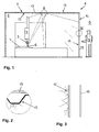
- a working chamber 1 designed as a laser protective cabin accommodates a laser processing device 3 in the working space interior 2, which in the illustrated example is designed as a laser cutting device for the 3D machining of workpieces 4. From a laser cutting head 5 of the laser machining device 3, a laser beam 6 is directed onto the workpiece 4 to be machined in the regular cutting operation.
- the laser beam 6 is partially reflected at the surface of the workpiece 4.
- the emitted from the surface of the workpiece 4 laser radiation strikes the inside of a working space separation 7.
- the work space partition 7 comprises a vertical wall area 10 and a horizontal ceiling area 11. Both in the wall area 10 and in the ceiling area 11, the work space partition 7 has at its the laser processing unit 3 facing inside a laser beam reflector 12.
- the laser beam reflector 12 is formed from the surface of blanks of aluminum sheet having a thickness of 1 mm.
- In the ceiling area 11 of the working space partition 7 trapezoidal sheets are provided as sheet metal blanks. Both in the wall area 10 and in the ceiling area 11 of the working space partition 7, the sheet metal blanks are screwed to an outer layer or outer shell 13 of the working space partition 7.
- the outer shell 13 of the working space partition 7 is made of two millimeters thick sheet steel.
- the aluminum sheet of the laser beam reflector 12 is commercially available. In construction, for example, it is used as a façade or roof cladding, among other things.
- the sheet metal surface which forms the laser beam reflector 12 is blank and has a spatial surface structure, which is hinted at in FIGS. 2 and 3. In Figure 1, the laser beam reflector 12 is shown for simplicity as a flat surface.
- the spatial surface structure of the aluminum sheet used for the laser beam reflector 12 is irregular and approximately corresponds to the surface texture of grained leather. Commercially, this surface structure is available under the name “stucco mentionediert”. Alternatively, inter alia, the use of aluminum sheet with regularly structured surface, for example with spherical structures conceivable.
- Decisive is the reflection behavior of the sheet metal surface. On the one hand, it must be ensured that the laser radiation originating from the laser processing device 3 is predominantly reflected on the sheet metal surface forming the laser beam reflector 12. This requirement is met by the laser beam reflector 12 forming bare aluminum surface of the embodiment shown to a high degree. Thus, the laser beam reflector 12 reflects about 99% of the laser radiation incident on it. This extraordinarily high reflectance is achieved at the wavelength of the laser light incident on the laser beam reflector 12 in the exemplary case shown. The wavelength of the laser light in turn depends on the design of the beam source. To generate the laser beam 6, a CO 2 generator is used.
- the laser light incident on the laser beam reflector 12 were to be generated by means of an NdYAG laser, then it would be possible to use the bare aluminum surface of the laser beam Embodiment achieve a reflectance of about 90%. Due to the selected surface structure of the laser beam reflector 12, a reflectance of the mentioned order of magnitude is achieved even with a contamination of the laser beam reflector 12 that is common in the vicinity of laser cutting devices.
- the surface structure of the laser beam reflector 12 ensures a diffuse reflection of the incident laser light, as indicated in FIGS. 2 and 3.
- the energy densities in the laser light radiated by the laser beam reflector 12 are therefore at a merely low level.
- the energy densities mentioned are too low to cause damage in the working chamber interior 2, in particular on the laser processing device 3. Consequently, for example, otherwise required for protective bellows for bellows of the laser processing device 3 can be omitted.
- the described protective effect inwardly and outwardly unfolds the laser beam reflector 12 even in irregular operating conditions of the laser processing device 3, such as when the laser beam 6 is directed by the laser cutting head 5 accidentally on the laser beam reflector 12.
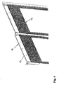
- FIG. 4 shows the laser beam reflector 12 on the outer shell 13 of the working space partition 7 in the view of working space inside 2.
- the illustrated wall area is provided with window cutouts.
- the surface structure of the laser beam reflector 12 can be clearly seen.
- FIG. 5 shows a screw connection between the laser beam reflector 12 and the outer shell 13 of the working space partition 7 in detail.
- the laser beam reflector 12 is held by a spacer sleeve 14 at a distance from the outer shell 13.
- the resulting gap between the laser beam reflector 12 and the outer shell 13 of the working space partition 7 is used for thermal insulation of the outer shell 13 against the laser radiation acted upon by the laser beam reflector 12.
- the spacer sleeve 14 is penetrated by a bolt 15, which at its outer shell 13 associated longitudinal end with a foot plate 16 is welded.
- the foot plate 16 is glued to a double-sided self-adhesive blank 17 made of sponge rubber.
- the blank 17, in turn, is bonded to the outer shell 13 on its side remote from the base plate 16.
- the laser beam reflector 12 is clamped between a nut 18 and the spacer sleeve 14. Corresponding connections between the laser beam reflector 12 and the outer shell 13 of the working space partition 7 are made at the remaining attachment points of the laser beam reflector 12.
- the nuts 18 or the adhesive bonds between the blanks 17 of the individual fastening devices and the outer shell 13 are to be loosened.
- the old blanks 17 on the base plates 16 of the various fastening devices are replaced by new blanks with still unused adhesive surfaces in the latter case.
- the laser beam reflector 12 can be adhered to the applied on the base plates 16 new blanks 17 on the inside of the outer shell 13 of the working space separation 7.
- FIG. 6 shows a working space partition 19 with a laser beam reflector 20 and an outer layer or outer shell 21.
- the laser beam reflector 20 is folded at its edge in a U-shaped manner. Between two legs of the U-shaped fold of the laser beam reflector 20 and the outer shell 21 each have a Velcro connection 22 is made.
- Velcro connection 22 allow handling-friendly assembly and disassembly of the laser beam reflector 20.
- Both the laser beam reflector 12 according to FIG. 5 and the laser beam reflector 20 according to FIG. 6 are characterized by a "stucco-patterned" surface of blanks made of aluminum sheet. A detailed illustration of said surface structure has been omitted in FIGS. 5 and 6 for reasons of simplicity of illustration.
Landscapes
- Engineering & Computer Science (AREA)
- Physics & Mathematics (AREA)
- Optics & Photonics (AREA)
- Mechanical Engineering (AREA)
- Plasma & Fusion (AREA)
- General Engineering & Computer Science (AREA)
- General Physics & Mathematics (AREA)
- Laser Beam Processing (AREA)
Abstract
Description
Die Erfindung betrifft einen Arbeitsraum mit einer Laser-Bearbeitungseinrichtung im Arbeitsrauminnern sowie mit einer Arbeitsraumabtrennung zwischen dem Arbeitsrauminnern und der Arbeitsraumumgebung. Die Erfindung betrifft des Weiteren eine Arbeitsraumabtrennung der genannten Art sowie einen Laserstrahlreflektor hierfür.The invention relates to a work space with a laser processing device in the working space interior and with a working space separation between the working space interior and the working space environment. The invention further relates to a working space separation of the type mentioned and a laser beam reflector for this purpose.
Arbeitsräume, in denen Laser-Bearbeitungseinrichtungen betrieben werden, sind insbesondere aus Gründen des Arbeitsschutzes gegen ihre Umgebung abzuschirmen. Gemäß den einschlägigen Sicherheitsvorschriften muss gewährleistet sein, dass unter anderem auch bei irregulären Betriebszuständen der Laser-Bearbeitungseinrichtung und zumindest für eine begrenzte Zeitdauer keine schädliche Laserstrahlung aus dem Arbeitsrauminnern in die Arbeitsraumumgebung austreten kann. Zu diesem Zweck dienen Arbeitsraumabtrennungen, so genannte "Laserschutzwände".Work rooms in which laser processing facilities are operated, in particular for reasons of occupational safety against their environment shield. According to the relevant safety regulations, it must be ensured that, inter alia, even in the event of irregular operating states of the laser processing device and for at least a limited period of time, no harmful laser radiation can escape from the working chamber interior into the working environment. For this purpose, working space separations, so-called "laser protection walls" are used.
Ein gattungsgemäßer Arbeitsraum sowie eine gattungsgemäße Arbeitsraumabtrennung sind offenbart in
Die aus
Das Ausmaß der in die vorbekannte Laserschutzwand eingekoppelten Strahlungsenergie wirkt sich negativ auf die Standzeit der Laserschutzwand unter Strahlungsbelastung aus. Dies wiederum beeinträchtigt die Eignung der vorbekannten Laserschutzwand als Einrichtung des Arbeitsschutzes.The extent of the coupled into the previously known laser protective wall radiation energy has a negative effect on the service life of the laser protective wall under radiation exposure. This in turn impairs the suitability of the previously known laser protective wall as a device of occupational safety.
Die Aufgabe der vorliegenden Erfindung besteht darin, an einem Arbeitsraum der eingangs genannten Art maximalen Arbeitsschutz in Kombination mit maximaler Betriebssicherheit der in dem Arbeitsraum untergebrachten Laser-Bearbeitungseinrichtung zu gewährleisten.The object of the present invention is to ensure maximum occupational safety in combination with maximum operational safety of the laser processing device accommodated in the working space in a working space of the type mentioned in the introduction.
Erfindungsgemäß gelöst wird diese Aufgabe durch den Arbeitsraum gemäß Patentanspruch 1, durch die Arbeitsraumabtrennung gemäß Patentanspruch 16 sowie durch den Laserstrahlreflektor gemäß Patentanspruch 17.This object is achieved according to the invention by the working space according to
Im Falle der Erfindung ist an der Innenseite der Arbeitsraumabtrennung ein Laserstrahlreflektor vorgesehen, welcher den überwiegenden Teil der an dem Verlassen des Arbeitsrauminnern zu hindernden Laserstrahlung reflektiert. Der hohe Reflexionsgrad des erfindungsgemäßen Laserstrahlreflektors verhindert, dass Strahlungsenergie der an dem Laserstrahlreflektor einfallenden Laserstrahlung in einem Ausmaß in die Arbeitsraumabtrennung eingekoppelt wird, das bereits nach kurzer Zeit zu einer Überhitzung und einer damit verbundenen Zerstörung der Arbeitsraumabtrennung führen würde. Insofern gewährleisten die Merkmale der Erfindung einen maximalen Arbeitsschutz.In the case of the invention, a laser beam reflector is provided on the inside of the working space separation, which reflects the vast majority of the laser radiation to be prevented from leaving the working chamber interior. The high reflectance of the laser beam reflector according to the invention prevents radiation energy of the laser radiation incident on the laser beam reflector from being coupled into the working space separation to an extent which would lead to overheating and an associated destruction of the working space separation after a short time. In this respect, the features of the invention ensure maximum occupational safety.
Gleichzeitig wird die einfallende Laserstrahlung von dem erfindungsgemäßen Laserstrahlreflektor nicht gerichtet sondern vielmehr diffus reflektiert. In Folge ihrer Streuung besitzt die reflektierte Laserstrahlung eine lediglich geringe Energiedichte und ist daher nicht in der Lage, im Arbeitsrauminnern, insbesondere an der dort angeordneten Laser-Bearbeitungseinrichtung Schaden anzurichten. Insofern sorgt die Erfindung für eine Maximierung der Betriebssicherheit der Laser-Bearbeitungseinrichtung. Ansonsten zu verwendende Schutzeinrichtungen an der Laser-Bearbeitungseinrichtung, beispielsweise Schutzhauben für Faltenbälge, sind verzichtbar.At the same time, the incident laser radiation is not directed by the laser beam reflector according to the invention but rather diffusely reflected. As a result of their scattering, the reflected laser radiation has only a low energy density and is therefore unable to cause damage in the working space interior, in particular on the laser processing device arranged there. In this respect, the invention provides for maximizing the reliability of the laser processing device. Otherwise protective devices to be used on the laser processing device, such as protective covers for bellows are dispensable.
Sowohl unter dem Gesichtspunkt des Arbeitsschutzes als auch unter dem Aspekt der Betriebssicherheit der Laser-Bearbeitungseinrichtung sind die erfindungsgemäßen Merkmale dann von besonderem Vorteil, wenn an der Laser-Bearbeitungseinrichtung mit Laserstrahlung hoher Leistung gearbeitet wird.Both from the point of view of occupational safety and in terms of operational safety of the laser processing device features of the invention are then of particular advantage when working on the laser processing device with laser radiation high power.
Besondere Ausführungsarten der Erfindung gemäß den Patentansprüchen 1, 16 und 17 ergeben sich aus den abhängigen Patentansprüchen 2 bis 15.Particular embodiments of the invention according to
Die Erfindungsbauart nach Patentanspruch 2 zeichnet sich dadurch aus, dass der Laserstrahlreflektor materialbezogen auf die Wellenlänge der zu reflektierenden Laserstrahlung abgestimmt ist. Auf diese Art und Weise ist sichergestellt, dass auch tatsächlich der überwiegende Teil der an dem Laserstrahlreflektor einfallenden Laserstrahlung reflektiert wird. Die Wellenlänge des zu reflektierenden Laserlichtes ist abhängig von der Bauart der Strahlquelle. Etwa an einem Laserstrahlreflektor aus Aluminium kann CO2-Laserlicht zu 99%, NdYAG-Laserlicht zu 90% reflektiert werden. Generell werden erfindungsgemäß Laserstrahlreflektoren mit einem Reflexionsgrad von wenigstens 90% bevorzugt. Bei einem derartigen Reflexionsgrad des Laserstrahlreflektors lassen sich hinreichende Standzeiten der Arbeitsraumabtrennung gewährleisten.The invention type of construction according to
Besonders praxistauglich sind Laserstrahlreflektoren in Form diffus reflektierender metallischer Oberflächen (Patentanspruch 3). Derartige Laserstrahlreflektoren lassen sich verhältnismäßig einfach fertigen und zeigen aufgrund ihrer Robustheit auch unter rauen Einsatzbedingungen und über eine lange Einsatzdauer die erforderliche Reflexionsfähigkeit.Particularly practical are laser beam reflectors in the form of diffusely reflecting metallic surfaces (claim 3). Such laser beam reflectors can be relatively easily manufactured and show the required reflectivity due to their robustness even under harsh operating conditions and over a long period of use.
Als Werkstoffe für als Laserstrahlreflektoren dienende metallische Oberflächen kommen erfindungsgemäß verschiedene Metalle in Frage (Patentanspruch 4). Als Laserstrahlreflektor bevorzugt wird im Falle der Erfindung eine diffus reflektierende Aluminiumoberfläche. Derartige Laserstrahlreflektoren sind insbesondere kostengünstig. Außerdem empfiehlt sich die Verwendung von Aluminium als Reflektorwerkstoff aufgrund seiner (beispielsweise verglichen mit Kupfer) verhältnismäßig geringen Wärmeleitfähigkeit und aufgrund seines geringen Gewichts. Schließlich lässt sich mit Aluminium - wie vorstehend zu Patentanspruch 2 dargelegt - bei unterschiedlichen Wellenlängen des zu reflektierenden Laserlichtes stets ein hoher Reflexionsgrad erreichen.As materials for serving as laser beam reflectors metallic surfaces according to the invention various metals in question (claim 4). As a laser beam reflector is preferred in the case of the invention, a diffusely reflecting aluminum surface. Such laser beam reflectors are particularly inexpensive. In addition, the use of aluminum as a reflector material due to its (for example compared to copper) relatively low thermal conductivity and due to its low weight is recommended. Finally, with aluminum - as above to claim 2 explained - always achieve a high reflectance at different wavelengths of the laser light to be reflected.
Der Einfachheit halber, insbesondere im Interesse einer möglichst einfachen und kostengünstigen Fertigung, wird im Falle der Erfindung als den Laserstrahlreflektor bildende diffus reflektierende Oberfläche eine blanke Oberfläche gegebenenfalls eine blanke metallische Oberfläche, bevorzugt.For the sake of simplicity, in particular in the interest of the simplest possible and cost-effective production, in the case of the invention as the laser beam reflector forming diffuse reflective surface is a bare surface, where appropriate, a bare metallic surface, preferred.
Der Laserstrahlreflektor, gegebenenfalls die den Laserstrahlreflektor bildende metallische Oberfläche, kann von einer auf einem Träger aufgebrachten Beschichtung gebildet sein (Patentanspruch 6). Als Beschichtungsverfahren kommen beispielsweise das Flammspritzen oder Metall-Abscheideverfahren in Frage.The laser beam reflector, optionally the metal surface forming the laser beam reflector, may be formed by a coating applied to a carrier (claim 6). As a coating method, for example, the flame spraying or metal deposition process come into question.
Im Interesse einer besonders einfachen und kostengünstigen Fertigung empfiehlt es sich, als Laserstrahlreflektor unmittelbar eine Oberfläche eines Reflektorkörpers vorzusehen (Patentanspruch 7). Das Aufbringen einer als Laserstrahlreflektor dienenden Oberflächenbeschichtung auf einen Träger erübrigt sich in diesem Fall.In the interests of a particularly simple and cost-effective production, it is recommended to provide a laser beam reflector directly a surface of a reflector body (claim 7). The application of a surface coating serving as a laser beam reflector on a support is unnecessary in this case.
In bevorzugter Ausgestaltung der Erfindung ist als mit seiner Oberfläche den Laserstrahlreflektor bildender Reflektorkörper ein Metallkörper, insbesondere ein Metallblech, vorgesehen (Patentanspruch 8). Erfindungsgemäß bevorzugt wird ein Aluminiumblech, das mit einer blanken und diffus reflektierenden Aluminiumoberfläche den Laserstrahlreflektor bildet.In a preferred embodiment of the invention is as a surface with the laser beam reflector forming reflector body, a metal body, in particular a metal sheet provided (claim 8). According to the invention, preference is given to an aluminum sheet which forms the laser beam reflector with a bare and diffusely reflecting aluminum surface.
Eine diffuse Reflexion der einfallenden Laserstrahlung durch den Laserstrahlreflektor kann erfindungsgemäß auf unterschiedliche Art und Weise bewirkt werden.A diffuse reflection of the incident laser radiation by the laser beam reflector can be effected according to the invention in different ways.
Aus fertigungstechnischen Gründen ist es empfehlenswert, den Laserstrahlreflektor mit einer entsprechenden räumlichen Oberflächenstruktur zu versehen (Patentanspruch 9). Dabei lässt sich eine besonders intensive Streuung des reflektierten Laserlichtes mittels unregelmäßig profilierter Oberflächenstrukturen erzielen (Patentanspruch 10). Gleichwohl sind aber auch Laserstrahlreflektoren mit regelmäßig profilierter Oberflächenstruktur denkbar. Beispielsweise durch prägende Bearbeitung lassen sich insbesondere an Blechen, die unmittelbar mit ihrer Oberfläche den Laserstrahlreflektor bilden, erfindungsgemäße Oberflächenstrukturen erzeugen.For manufacturing reasons, it is recommended to provide the laser beam reflector with a corresponding spatial surface structure (claim 9). In this case, a particularly intensive scattering of the reflected laser light by means of irregularly profiled surface structures can be achieved (claim 10). Nevertheless, however, laser beam reflectors with a regularly profiled surface structure are also conceivable. For example, by embossing processing can be particularly on sheets, directly with their Surface form the laser beam reflector, produce surface structures according to the invention.
Handelsüblich und somit vorteilhafterweise frei verfügbar sind genarbte Oberflächenstrukturen (Patentanspruch 11).Commercially available and thus advantageously freely available are grained surface structures (claim 11).
Eine optimale Funktionsfähigkeit erfindungsgemäßer Laserstrahlreflektoren setzt deren Formstabilität voraus. Zur Gewährleistung dieser Formstabilität sind im Falle der Erfindungsbauart nach Patentanspruch 12 versteifende Verformungen an dem mit einer diffus reflektierenden Beschichtung versehenen Träger bzw. an dem eine diffus reflektierende Oberfläche ausbildenden Reflektorkörper vorgesehen. Als handelsübliche und somit ohne weiteres erhältliche Träger bzw. Reflektorkörper bieten sich Trapezbleche an (Patentanspruch 13). Versteifungen der genannten Art sind insbesondere dann zweckmäßig, wenn der Laserstrahlreflektor im Deckenbereich des Arbeitsraumes bzw. der Arbeitsraumabtrennung vorgesehen ist.Optimum functionality of laser beam reflectors according to the invention requires their dimensional stability. To ensure this dimensional stability stiffening deformations are provided in the case of Erfindungsbauart according to
Gemäß Patentanspruch 14 ist ein Laserstrahlreflektor Teil einer Arbeitsraumabtrennung, die außerdem eine Außenlage umfasst, die ihrerseits an der von der Laser-Bearbeitungseinrichtung abgewandten Seite des Laserstrahlreflektors angeordnet ist. Zweckmäßigerweise ist der Laserstrahlreflektor dabei mit der Außenlage der Arbeitsraumabtrennung lösbar verbunden. Aufgrund dieser lösbaren Verbindung lässt sich beispielsweise ein defekter bzw. verschlissener Laserstrahlreflektor auf einfache Art und Weise gegen einen voll funktionsfähigen Laserstrahlreflektor austauschen. Auch lässt sich ein Laserstrahlreflektor etwa zur Durchführung von Wartungs-, insbesondere von Reinigungsarbeiten, problemlos von der zugehörigen Außenlage der Arbeitsraumabtrennung abnehmen und nach der Wartung bzw. Reinigung wieder an der Außenlage anbringen.According to
Im Interesse einer thermischen Isolierung der Außenlage der Arbeitsraumabtrennung gegen den Laserstrahlreflektor verbleibt im Falle der Erfindungsbauart nach Patentanspruch 15 zwischen dem Laserstrahlreflektor und der Außenlage der Arbeitsraumabtrennung ein Zwischenraum.In the interest of a thermal insulation of the outer layer of the workspace separation against the laser beam reflector remains in the case of Erfindungsbauart according to
Nachstehend wird die Erfindung anhand beispielhafter und stark schematisierter Darstellungen näher erläutert. Es zeigen:
Figur 1- einen Arbeitsraum in Form einer Laserschutzkabine mit einer Laser-Bearbeitungseinrichtung und einer Arbeitsraumabtrennung,
Figur 2- das Detail II von
Figur 1, - Figur 3
- das Detail III von
Figur 1, - Figur 4
- einen Teilbereich der Arbeitsraumabtrennung gemäß Figur 1 in der perspektivischen Ansicht vom Arbeitsrauminnern her,
Figur 5- eine Schnittdarstellung der Arbeitsraumabtrennung gemäß Figur 1 und
- Figur 6
- eine Schnittdarstellung einer zweiten Bauart einer Arbeitsraumabtrennung.
- FIG. 1
- a working space in the form of a laser protection cabin with a laser processing device and a working space separation,
- FIG. 2
- the detail II of Figure 1,
- FIG. 3
- the detail III of Figure 1,
- FIG. 4
- a partial area of the working space partition according to FIG. 1 in the perspective view from the working space interior,
- FIG. 5
- a sectional view of the working space separation according to Figure 1 and
- FIG. 6
- a sectional view of a second type of workspace separation.
Gemäß Figur 1 beherbergt ein als Laserschutzkabine ausgebildeter Arbeitsraum 1 im Arbeitsrauminnern 2 eine Laser-Bearbeitungseinrichtung 3, die im dargestellten Beispielsfall als Laserschneideinrichtung für die 3D-Bearbeitung von Werkstücken 4 ausgeführt ist. Von einem Laserschneidkopf 5 der Laser-Bearbeitungseinrichtung 3 aus wird im regulären Schneidbetrieb ein Laserstrahl 6 auf das zu bearbeitende Werkstück 4 gerichtet.According to FIG. 1, a working
Wie in Figur 1 angedeutet, wird der Laserstrahl 6 an der Oberfläche des Werkstückes 4 teilweise reflektiert. Die von der Oberfläche des Werkstückes 4 abgestrahlte Laserstrahlung trifft auf die Innenseite einer Arbeitsraumabtrennung 7. Diese umgibt die Laser-Bearbeitungseinrichtung 3 haubenartig und schirmt das Arbeitsrauminnere 2 gegen die Arbeitsraumumgebung 8 ab. In der Arbeitsraumumgebung 8 hält sich eine Bedienperson 9 auf.As indicated in FIG. 1, the laser beam 6 is partially reflected at the surface of the workpiece 4. The emitted from the surface of the workpiece 4 laser radiation strikes the inside of a working
Die Arbeitsraumabtrennung 7 umfasst einen vertikalen Wandbereich 10 sowie einen horizontalen Deckenbereich 11. Sowohl in dem Wandbereich 10 als auch in dem Deckenbereich 11 weist die Arbeitsraumabtrennung 7 an ihrer der Laser-Bearbeitungseinheit 3 zugewandten Innenseite einen Laserstrahlreflektor 12 auf. Der Laserstrahlreflektor 12 wird gebildet von der Oberfläche von Zuschnitten aus Aluminiumblech mit einer Dicke von 1 mm. In dem Deckenbereich 11 der Arbeitsraumabtrennung 7 sind als Blechzuschnitte Trapezbleche vorgesehen. Sowohl in dem Wandbereich 10 als auch in dem Deckenbereich 11 der Arbeitsraumabtrennung 7 sind die Blechzuschnitte mit einer Außenlage bzw. Außenschale 13 der Arbeitsraumabtrennung 7 verschraubt. Die Außenschale 13 der Arbeitsraumabtrennung 7 ist aus zwei Millimeter dickem Stahlblech gefertigt.The
Das Aluminiumblech des Laserstrahlreflektors 12 ist handelsüblich. Etwa im Baubereich wird es unter anderem als Fassaden- oder Dachverkleidung verwendet. Die Blechoberfläche, welche den Laserstrahlreflektor 12 ausbildet, ist blank und besitzt eine räumliche Oberflächenstruktur, die in den Figuren 2 und 3 andeutungsweise gezeigt ist. In Figur 1 ist der Laserstrahlreflektor 12 der Einfachheit halber als ebene Oberfläche dargestellt.The aluminum sheet of the
Die räumliche Oberflächenstruktur des für den Laserstrahlreflektor 12 verwendeten Aluminiumblechs ist unregelmäßig und entspricht in etwa der Oberflächenstruktur von genarbtem Leder. Im Handel ist diese Oberflächenstruktur unter der Bezeichnung "stucco dessiniert" erhältlich. Alternativ wäre unter anderem auch der Einsatz von Aluminiumblech mit regelmäßig strukturierter Oberfläche, beispielsweise mit sphärischen Strukturen denkbar.The spatial surface structure of the aluminum sheet used for the
Ausschlaggebend ist das Reflexionsverhalten der Blechoberfläche. Zum einen muss gewährleistet sein, dass die von der Laser-Bearbeitungseinrichtung 3 stammende Laserstrahlung an der den Laserstrahlreflektor 12 bildenden Blechoberfläche zum überwiegenden Teil reflektiert wird. Diese Voraussetzung wird von der den Laserstrahlreflektor 12 bildenden blanken Aluminiumoberfläche des gezeigten Ausführungsbeispiels in hohem Maße erfüllt. So reflektiert der Laserstrahlreflektor 12 rund 99% der an ihm einfallenden Laserstrahlung. Erreicht wird dieser außerordentlich hohe Reflexionsgrad bei der Wellenlänge des in dem gezeigten Beispielfall auf den Laserstrahlreflektor 12 treffenden Laserlichtes. Die Wellenlänge des Laserlichtes wiederum ist abhängig von der Bauart der Strahlquelle. Zur Erzeugung des Laserstrahles 6 wird ein CO2-Generator eingesetzt. Würde das an dem Laserstrahlreflektor 12 einfallende Laserlicht mittels eines NdYAG-Lasers erzeugt, so ließe sich mit der blanken Aluminiumoberfläche des Ausführungsbeispiels ein Reflexionsgrad von rund 90% erzielen. Aufgrund der gewählten Oberflächenstruktur des Laserstrahlreflektors 12 wird ein Reflexionsgrad in der genannten Größenordnung selbst bei einer im Nahbereich von Laserschneideinrichtungen üblichen Verschmutzung des Laserstrahlreflektors 12 erreicht.Decisive is the reflection behavior of the sheet metal surface. On the one hand, it must be ensured that the laser radiation originating from the laser processing device 3 is predominantly reflected on the sheet metal surface forming the
Aufgrund des hohen Reflexionsvermögens des Laserstrahlreflektors 12 kommt es unter der Wirkung des an dem Laserstrahlreflektor 12 einfallenden Laserlichtes zu einer lediglich geringen Erwärmung des Laserstrahlreflektors 12 und somit der gesamten Arbeitsraumabtrennung 7. Die Arbeitsraumabtrennung 7 erreicht daher lange Standzeiten.Due to the high reflectivity of the
Gleichzeitig sorgt die Oberflächenstruktur des Laserstrahlreflektors 12 für eine diffuse Reflexion des einfallenden Laserlichtes, wie sie in den Figuren 2 und 3 angedeutet ist. Die Energiedichten in dem von dem Laserstrahlreflektor 12 abgestrahlten Laserlicht liegen daher auf einem lediglich niedrigen Niveau. Insbesondere sind die genannten Energiedichten zu gering, als dass sie in dem Arbeitsrauminnern 2, insbesondere an der Laser-Bearbeitungseinrichtung 3 Schäden verursachen könnten. Folglich kann beispielsweise auf ansonsten benötigte Schutzhauben für Faltenbälge der Laser-Bearbeitungseinrichtung 3 verzichtet werden.At the same time, the surface structure of the
Die beschriebene Schutzwirkung nach innen und nach außen entfaltet der Laserstrahlreflektor 12 auch bei irregulären Betriebszuständen der Laser-Bearbeitungseinrichtung 3, etwa dann, wenn der Laserstrahl 6 von dem Laserschneidkopf 5 versehentlich auf den Laserstrahlreflektor 12 gerichtet wird.The described protective effect inwardly and outwardly unfolds the
Figur 4 zeigt den Laserstrahlreflektor 12 an der Außenschale 13 der Arbeitsraumabtrennung 7 in der Ansicht von Arbeitsrauminnern 2 her. Der dargestellte Wandbereich ist mit Fensterausschnitten versehen. Deutlich zu erkennen ist die Oberflächenstruktur des Laserstrahlreflektors 12.FIG. 4 shows the
Figur 5 zeigt eine Schraubverbindung zwischen dem Laserstrahlreflektor 12 und der Außenschale 13 der Arbeitsraumabtrennung 7 im Detail.FIG. 5 shows a screw connection between the
Demnach wird der Laserstrahlreflektor 12 mittels einer Distanzhülse 14 auf Abstand von der Außenschale 13 gehalten. Der sich damit ergebende Zwischenraum zwischen dem Laserstrahlreflektor 12 und der Außenschale 13 der Arbeitsraumabtrennung 7 dient der thermischen Isolierung der Außenschale 13 gegen den durch Laserstrahlung beaufschlagten Laserstrahlreflektor 12. Die Distanzhülse 14 wird von einem Schraubenbolzen 15 durchsetzt, der an seinem der Außenschale 13 zugeordneten Längsende mit einer Fußplatte 16 verschweißt ist. Die Fußplatte 16 ist auf einen beidseitig selbstklebenden Zuschnitt 17 aus Moosgummi aufgeklebt. Der Zuschnitt 17 wiederum ist an seiner von der Fußplatte 16 abliegenden Seite mit der Außenschale 13 verklebt. An dem freien Ende des Schraubenbolzens 15 ist der Laserstrahlreflektor 12 zwischen einer Mutter 18 und der Distanzhülse 14 verspannt. Entsprechende Verbindungen zwischen dem Laserstrahlreflektor 12 und der Außenschale 13 der Arbeitsraumabtrennung 7 sind an den übrigen Befestigungsstellen des Laserstrahlreflektors 12 hergestellt.Accordingly, the
Zur Demontage des Laserstrahlreflektors 12 sind entweder die Muttern 18 oder die Klebverbindungen zwischen den Zuschnitten 17 der einzelnen Befestigungseinrichtungen und der Außenschale 13 zu lösen. Zur Neumontage des Laserstrahlreflektors 12 werden in dem letztgenannten Fall die alten Zuschnitte 17 an den Fußplatten 16 der verschiedenen Befestigungsvorrichtungen durch neue Zuschnitte mit noch unbenutzten Klebeflächen ersetzt. Anschließend lässt sich der Laserstrahlreflektor 12 an den auf die Fußplatten 16 aufgebrachten neuen Zuschnitten 17 auf die Innenseite der Außenschale 13 der Arbeitsraumabtrennung 7 aufkleben.To disassemble the
Figur 6 zeigt eine Arbeitsraumabtrennung 19 mit einem Laserstrahlreflektor 20 und einer Außenlage bzw. Außenschale 21. Der Laserstrahlreflektor 20 ist an seinem Rand U-förmig abgekantet. Zwischen zwei Schenkeln der U-förmigen Abkantung des Laserstrahlreflektors 20 und der Außenschale 21 ist jeweils eine Klettverbindung 22 hergestellt. Zu diesem Zweck sind einerseits an dem Laserstrahlreflektor 20 und andererseits an der Außenschale 21 herkömmliche Klettbandabschnitte angebracht. Die Klettverbindungen 22 gestatten eine handhabungsfreundliche Montage und Demontage des Laserstrahlreflektors 20.FIG. 6 shows a working
Sowohl der Laserstrahlreflektor 12 gemäß Figur 5 als auch der Laserstrahlreflektor 20 gemäß Figur 6 wird von einer "stucco dessinierten" Oberfläche von Zuschnitten aus Aluminiumblech gebildet. Von einer detaillierten Darstellung der genannten Oberflächenstruktur wurde in den Figuren 5 und 6 aus Gründen der Darstellungsvereinfachung abgesehen.Both the
Claims (17)
Priority Applications (3)
| Application Number | Priority Date | Filing Date | Title |
|---|---|---|---|
| EP06020907A EP1908546A1 (en) | 2006-10-05 | 2006-10-05 | Diffuse laser beam reflector ; Room separation and working room with laser processing system with such a laser beam reflector |
| US11/868,118 US7800087B2 (en) | 2006-10-05 | 2007-10-05 | Workroom partition |
| CNU2007201255817U CN201183172Y (en) | 2006-10-05 | 2007-10-08 | Machining cell isolation device and machining cell |
Applications Claiming Priority (1)
| Application Number | Priority Date | Filing Date | Title |
|---|---|---|---|
| EP06020907A EP1908546A1 (en) | 2006-10-05 | 2006-10-05 | Diffuse laser beam reflector ; Room separation and working room with laser processing system with such a laser beam reflector |
Publications (1)
| Publication Number | Publication Date |
|---|---|
| EP1908546A1 true EP1908546A1 (en) | 2008-04-09 |
Family
ID=37805947
Family Applications (1)
| Application Number | Title | Priority Date | Filing Date |
|---|---|---|---|
| EP06020907A Ceased EP1908546A1 (en) | 2006-10-05 | 2006-10-05 | Diffuse laser beam reflector ; Room separation and working room with laser processing system with such a laser beam reflector |
Country Status (3)
| Country | Link |
|---|---|
| US (1) | US7800087B2 (en) |
| EP (1) | EP1908546A1 (en) |
| CN (1) | CN201183172Y (en) |
Cited By (4)
| Publication number | Priority date | Publication date | Assignee | Title |
|---|---|---|---|---|
| EP2153928A1 (en) * | 2008-08-13 | 2010-02-17 | KraussMaffei Technologies GmbH | Stamping and cutting device for plastic components with a robot carrying a laser device |
| DE102010042564B3 (en) * | 2010-10-18 | 2012-03-22 | Trumpf Laser- Und Systemtechnik Gmbh | Laser protection cabin and laser processing system with it |
| DE102012006455A1 (en) * | 2012-03-30 | 2013-10-02 | Tomislav Kuzman | Use of a window comprising a frame and a glass plate, which comprises a heat insulating layer, for protecting an operator of a laser tool against laser radiation that is emitted by a laser tool |
| WO2023138713A1 (en) * | 2022-01-19 | 2023-07-27 | Meissner Ag | Protective housing for a laser device |
Families Citing this family (9)
| Publication number | Priority date | Publication date | Assignee | Title |
|---|---|---|---|---|
| CN102011931B (en) * | 2010-11-26 | 2013-03-27 | 中冶赛迪工程技术股份有限公司 | Online anti-collision and anti-radiation device for O-shaped rack |
| CN102990231A (en) * | 2011-09-05 | 2013-03-27 | 佛吉亚(中国)投资有限公司 | Laser safety-type wall of welding room |
| US8683928B2 (en) | 2012-01-23 | 2014-04-01 | Honeywell International Inc. | Laser barrier system for optical tables |
| US20130326965A1 (en) * | 2012-06-06 | 2013-12-12 | GM Global Technology Operations LLC | Light tight enclosure assembly and method of providing a light tight work chamber |
| EP2886242B1 (en) * | 2013-12-20 | 2016-09-14 | TRUMPF Werkzeugmaschinen GmbH + Co. KG | Laser processing machine assembly, in particular with barrier free access |
| JP6633030B2 (en) * | 2017-07-14 | 2020-01-22 | 本田技研工業株式会社 | Laser light shielding device |
| HUE056429T2 (en) * | 2018-10-12 | 2022-02-28 | Dallan Spa | Apparatus for laser or plasma cutting of pieces of laminar material |
| CN113090082B (en) * | 2021-03-30 | 2022-10-21 | 贵州航天建设工程有限公司 | Radiographic inspection laboratory structure and construction method |
| JP2025136290A (en) * | 2024-03-07 | 2025-09-19 | プライムプラネットエナジー&ソリューションズ株式会社 | Battery assembly manufacturing device, battery assembly manufacturing method, and laser light attenuation mechanism |
Citations (6)
| Publication number | Priority date | Publication date | Assignee | Title |
|---|---|---|---|---|
| US4575610A (en) | 1984-03-12 | 1986-03-11 | Cincinnati Milacron Inc. | Laser shielding device |
| US4650287A (en) | 1984-07-23 | 1987-03-17 | Showa Denko Kabushiki Kaisha | Laser-light shield and method for shielding human body from laser light |
| GB2182746A (en) * | 1985-11-19 | 1987-05-20 | Prima Ind Spa | A protection device for carbon dioxide laser machines |
| US5309925A (en) | 1993-06-15 | 1994-05-10 | Med-Genesis, Inc. | Diffuse reflective laser barrier |
| US20050103755A1 (en) * | 2003-11-13 | 2005-05-19 | Baker Martin C. | Hand-held laser welding wand reflection shield |
| DE202006006823U1 (en) * | 2006-04-27 | 2006-08-24 | Frenzelit-Werke Gmbh & Co. Kg | Laser protection device has carrier layer made of inflammable textile and connected layer formed of sheet material with metal or ceramic oxide coating on exterior to diffuse laser light beam |
Family Cites Families (10)
| Publication number | Priority date | Publication date | Assignee | Title |
|---|---|---|---|---|
| US4578221A (en) * | 1980-04-23 | 1986-03-25 | Glaxo Group Limited | Androstane carbothioic acids |
| US4901738A (en) * | 1987-03-31 | 1990-02-20 | Minnesota Mining And Manufacturing Company | Laser shield |
| EP0300458B1 (en) * | 1987-07-21 | 1991-12-18 | Mitsubishi Jukogyo Kabushiki Kaisha | Laser beam welding method for an inner cicumferential surface of a tube |
| US5151095A (en) * | 1989-11-22 | 1992-09-29 | Teeple Jr Edward | Laser shield with indicator means |
| US5212387A (en) * | 1992-01-27 | 1993-05-18 | Charles H. Swan & Louis S. Pavloff, D.D. Ltd. | Laser radiation barrier |
| DE19629037C1 (en) * | 1996-07-18 | 1997-07-31 | Erwin Martin Heberer | Element of protection wall against laser radiation |
| DE19736042A1 (en) * | 1997-08-20 | 1999-02-25 | Alsthom Cge Alcatel | Device for longitudinal seam welding of metal pipes |
| US5992417A (en) * | 1998-03-02 | 1999-11-30 | Kentek Corporation | Portable, self-supporting, rigid laser containment barrier |
| US6571852B2 (en) * | 2001-08-28 | 2003-06-03 | Kentek Corporation | Colapsable, self-supporting, rigid laser containment barrier |
| EP1547112B1 (en) * | 2002-10-02 | 2007-06-20 | Siemens Aktiengesellschaft | Electromagnetic switching device |
-
2006
- 2006-10-05 EP EP06020907A patent/EP1908546A1/en not_active Ceased
-
2007
- 2007-10-05 US US11/868,118 patent/US7800087B2/en active Active
- 2007-10-08 CN CNU2007201255817U patent/CN201183172Y/en not_active Expired - Lifetime
Patent Citations (6)
| Publication number | Priority date | Publication date | Assignee | Title |
|---|---|---|---|---|
| US4575610A (en) | 1984-03-12 | 1986-03-11 | Cincinnati Milacron Inc. | Laser shielding device |
| US4650287A (en) | 1984-07-23 | 1987-03-17 | Showa Denko Kabushiki Kaisha | Laser-light shield and method for shielding human body from laser light |
| GB2182746A (en) * | 1985-11-19 | 1987-05-20 | Prima Ind Spa | A protection device for carbon dioxide laser machines |
| US5309925A (en) | 1993-06-15 | 1994-05-10 | Med-Genesis, Inc. | Diffuse reflective laser barrier |
| US20050103755A1 (en) * | 2003-11-13 | 2005-05-19 | Baker Martin C. | Hand-held laser welding wand reflection shield |
| DE202006006823U1 (en) * | 2006-04-27 | 2006-08-24 | Frenzelit-Werke Gmbh & Co. Kg | Laser protection device has carrier layer made of inflammable textile and connected layer formed of sheet material with metal or ceramic oxide coating on exterior to diffuse laser light beam |
Cited By (7)
| Publication number | Priority date | Publication date | Assignee | Title |
|---|---|---|---|---|
| EP2153928A1 (en) * | 2008-08-13 | 2010-02-17 | KraussMaffei Technologies GmbH | Stamping and cutting device for plastic components with a robot carrying a laser device |
| US8293155B2 (en) | 2008-08-13 | 2012-10-23 | Kraussmaffei Technologies Gmbh | Method and apparatus for stamping and cutting plastic parts |
| US8829474B2 (en) | 2010-10-08 | 2014-09-09 | Trumpf Laser- Und Systemtechnik Gmbh | Laser protection |
| DE102010042564B3 (en) * | 2010-10-18 | 2012-03-22 | Trumpf Laser- Und Systemtechnik Gmbh | Laser protection cabin and laser processing system with it |
| WO2012052304A1 (en) | 2010-10-18 | 2012-04-26 | Trumpf Laser- Und Systemtechnik Gmbh | Laser protection cabin and laser machining system equipped therewith |
| DE102012006455A1 (en) * | 2012-03-30 | 2013-10-02 | Tomislav Kuzman | Use of a window comprising a frame and a glass plate, which comprises a heat insulating layer, for protecting an operator of a laser tool against laser radiation that is emitted by a laser tool |
| WO2023138713A1 (en) * | 2022-01-19 | 2023-07-27 | Meissner Ag | Protective housing for a laser device |
Also Published As
| Publication number | Publication date |
|---|---|
| US20080173830A1 (en) | 2008-07-24 |
| CN201183172Y (en) | 2009-01-21 |
| US7800087B2 (en) | 2010-09-21 |
Similar Documents
| Publication | Publication Date | Title |
|---|---|---|
| EP1908546A1 (en) | Diffuse laser beam reflector ; Room separation and working room with laser processing system with such a laser beam reflector | |
| EP0279866B1 (en) | Manufacturing method for a shaped body of sheet metal pieces with different thicknesses | |
| DE69430151T2 (en) | Laser welding processes | |
| EP2629924B1 (en) | Laser protection cabin and laser machining system equipped therewith | |
| EP0461215A1 (en) | Noise-damping combination. | |
| EP0912858A2 (en) | Wall element for a protective device surrounding an operating or working area and protecting against laser beams from a laser source | |
| DE2758041C2 (en) | Use of a component consisting of at least two films, in particular plastic films, arranged one above the other | |
| DE102005017803A1 (en) | Composite laser beam welding | |
| WO2025132550A1 (en) | System and method for regionally removing the coating of a coated surface of a glass body, and regionally uncoated glass body | |
| DE202006021021U1 (en) | Working space with laser processing device and workspace separation and laser beam reflector for this purpose | |
| EP0900623B1 (en) | Safety shielding with a laser cutting machine | |
| EP4341145B1 (en) | Large component for a rail vehicle | |
| EP1674191A2 (en) | Two sheet-metal component manufacturing method and two sheet-metal component therefor. | |
| DE102014116746B4 (en) | Modular laser protection wall | |
| DE102023102028A1 (en) | Heat conducting sheet and method for producing one | |
| WO2011128118A1 (en) | Omega ultrasonic welding machine | |
| EP2905525B1 (en) | Assembly with at least one effective area for at least one laser | |
| DE3042347C2 (en) | Low-noise flame and plasma cutting device | |
| EP2978716A1 (en) | Method for cutting laminated glass | |
| DE102004056619B4 (en) | Process for the production of a heat exchanger partition with an armor and heat exchanger partition | |
| DE102004018170B4 (en) | Method for producing a composite pane with a multilayer foil laminate | |
| EP4522374B1 (en) | Laser transfer printing device and use thereof as well as method for coating a glass pane by way of laser transfer printing | |
| DE10304534A1 (en) | Folding roller of a folding device and method for its production | |
| DE202008011367U1 (en) | Sound enclosure | |
| EP3169617B1 (en) | Cover component for an escalator or a moving walkway |
Legal Events
| Date | Code | Title | Description |
|---|---|---|---|
| PUAI | Public reference made under article 153(3) epc to a published international application that has entered the european phase |
Free format text: ORIGINAL CODE: 0009012 |
|
| AK | Designated contracting states |
Kind code of ref document: A1 Designated state(s): AT BE BG CH CY CZ DE DK EE ES FI FR GB GR HU IE IS IT LI LT LU LV MC NL PL PT RO SE SI SK TR |
|
| AX | Request for extension of the european patent |
Extension state: AL BA HR MK RS |
|
| 17P | Request for examination filed |
Effective date: 20080418 |
|
| 17Q | First examination report despatched |
Effective date: 20080526 |
|
| AKX | Designation fees paid |
Designated state(s): AT BE BG CH CY CZ DE DK EE ES FI FR GB GR HU IE IS IT LI LT LU LV MC NL PL PT RO SE SI SK TR |
|
| STAA | Information on the status of an ep patent application or granted ep patent |
Free format text: STATUS: THE APPLICATION HAS BEEN REFUSED |
|
| 18R | Application refused |
Effective date: 20110201 |