EP1908902A2 - Single-point bolting device in particular for switching cabinets - Google Patents
Single-point bolting device in particular for switching cabinets Download PDFInfo
- Publication number
- EP1908902A2 EP1908902A2 EP07017522A EP07017522A EP1908902A2 EP 1908902 A2 EP1908902 A2 EP 1908902A2 EP 07017522 A EP07017522 A EP 07017522A EP 07017522 A EP07017522 A EP 07017522A EP 1908902 A2 EP1908902 A2 EP 1908902A2
- Authority
- EP
- European Patent Office
- Prior art keywords
- latch
- locking
- spring
- closing
- locking pin
- Prior art date
- Legal status (The legal status is an assumption and is not a legal conclusion. Google has not performed a legal analysis and makes no representation as to the accuracy of the status listed.)
- Withdrawn
Links
- 230000000903 blocking effect Effects 0.000 claims description 16
- 238000011161 development Methods 0.000 description 1
- 230000018109 developmental process Effects 0.000 description 1
- 230000000694 effects Effects 0.000 description 1
Images

Classifications
-
- E—FIXED CONSTRUCTIONS
- E05—LOCKS; KEYS; WINDOW OR DOOR FITTINGS; SAFES
- E05C—BOLTS OR FASTENING DEVICES FOR WINGS, SPECIALLY FOR DOORS OR WINDOWS
- E05C3/00—Fastening devices with bolts moving pivotally or rotatively
- E05C3/12—Fastening devices with bolts moving pivotally or rotatively with latching action
- E05C3/16—Fastening devices with bolts moving pivotally or rotatively with latching action with operating handle or equivalent member moving otherwise than rigidly with the latch
- E05C3/22—Fastening devices with bolts moving pivotally or rotatively with latching action with operating handle or equivalent member moving otherwise than rigidly with the latch the bolt being spring controlled
- E05C3/24—Fastening devices with bolts moving pivotally or rotatively with latching action with operating handle or equivalent member moving otherwise than rigidly with the latch the bolt being spring controlled in the form of a bifurcated member
-
- E—FIXED CONSTRUCTIONS
- E05—LOCKS; KEYS; WINDOW OR DOOR FITTINGS; SAFES
- E05B—LOCKS; ACCESSORIES THEREFOR; HANDCUFFS
- E05B47/00—Operating or controlling locks or other fastening devices by electric or magnetic means
- E05B47/0001—Operating or controlling locks or other fastening devices by electric or magnetic means with electric actuators; Constructional features thereof
- E05B47/0002—Operating or controlling locks or other fastening devices by electric or magnetic means with electric actuators; Constructional features thereof with electromagnets
-
- E—FIXED CONSTRUCTIONS
- E05—LOCKS; KEYS; WINDOW OR DOOR FITTINGS; SAFES
- E05B—LOCKS; ACCESSORIES THEREFOR; HANDCUFFS
- E05B47/00—Operating or controlling locks or other fastening devices by electric or magnetic means
- E05B47/06—Controlling mechanically-operated bolts by electro-magnetically-operated detents
- E05B47/0607—Controlling mechanically-operated bolts by electro-magnetically-operated detents the detent moving pivotally or rotatively
-
- E—FIXED CONSTRUCTIONS
- E05—LOCKS; KEYS; WINDOW OR DOOR FITTINGS; SAFES
- E05B—LOCKS; ACCESSORIES THEREFOR; HANDCUFFS
- E05B47/00—Operating or controlling locks or other fastening devices by electric or magnetic means
- E05B2047/0048—Circuits, feeding, monitoring
- E05B2047/0067—Monitoring
- E05B2047/0069—Monitoring bolt position
-
- E—FIXED CONSTRUCTIONS
- E05—LOCKS; KEYS; WINDOW OR DOOR FITTINGS; SAFES
- E05B—LOCKS; ACCESSORIES THEREFOR; HANDCUFFS
- E05B47/00—Operating or controlling locks or other fastening devices by electric or magnetic means
- E05B47/0001—Operating or controlling locks or other fastening devices by electric or magnetic means with electric actuators; Constructional features thereof
- E05B47/0002—Operating or controlling locks or other fastening devices by electric or magnetic means with electric actuators; Constructional features thereof with electromagnets
- E05B47/0006—Operating or controlling locks or other fastening devices by electric or magnetic means with electric actuators; Constructional features thereof with electromagnets having a non-movable core; with permanent magnet
-
- Y—GENERAL TAGGING OF NEW TECHNOLOGICAL DEVELOPMENTS; GENERAL TAGGING OF CROSS-SECTIONAL TECHNOLOGIES SPANNING OVER SEVERAL SECTIONS OF THE IPC; TECHNICAL SUBJECTS COVERED BY FORMER USPC CROSS-REFERENCE ART COLLECTIONS [XRACs] AND DIGESTS
- Y10—TECHNICAL SUBJECTS COVERED BY FORMER USPC
- Y10T—TECHNICAL SUBJECTS COVERED BY FORMER US CLASSIFICATION
- Y10T70/00—Locks
- Y10T70/50—Special application
- Y10T70/5093—For closures
- Y10T70/5155—Door
- Y10T70/5199—Swinging door
Definitions
- the invention relates to a locking device, in particular for control cabinets in the form of a single-point lock.
- Such single-point latches are known in the form of so-called sash closures, such as those in U.S. Patent Nos. 4,378,355 DE 298 06 963 described.
- a closure device with a rotatable tongue arranged thereon is attached to the door, which engages behind a part of the cabinet body and thereby locks the door with the cabinet body.
- the invention has for its object to provide a one-point locking device available, in which the closing and opening of the door by simply pressing or pulling on the door, while at the same time a secure locking of the door should be given if necessary.
- the invention provides for this purpose a locking device consisting of a mounted on the cabinet body and a lock having lock and a mounted on the door lock holder with a locking latch to be locked locking pin, the rotatably mounted locking latch both in their locking pin detecting the locking position is biased in its open position by means of a tilt spring and wherein a rotatable and biased by a spring in its blocking position for the locking latch locking lever for blocking a rotational movement of the latch is provided, which is energized by an energized for setting an opening readiness of the closing latch electromagnet against the force of Spring is pivotable in its release position for the latch.
- the latch is secured by a spring-biased safety lever in each case in its closed position, so that the door can not be mounted, but is provided to hold the intended safety lever out of engagement with the latch by means of a current-carrying electromagnet and thus to make an opening readiness of the latch, so that the Door opening can be made by pulling on the door with the associated overcoming of the force of the tilt spring.
- a microswitch assigned to the closing latch to be disposed in the lock for the purpose of emitting a signal.
- This has the advantage that the position of the latch can be queried by a signal such as the lighting of a lamp.
- the respective position of the latch can be displayed in its open position as well as in the locked position, so that it can be determined from outside the cabinet, if the door can be closed by pushing, because the latch is in its open position, or if the door is closed and the latch is in the locked position.
- the microswitch is actuated by the latch in its open position. At the same time, this also makes it possible to additionally emit a signal for the indication of the locking position of the closing latch.
- the locking lever rests in its blocking position against a located on the outer periphery of the latch paragraph.
- locking device consists initially of a not shown on a door of a particular cabinet to be mounted closure holder 10 which carries a locking pin 11.
- a lock 12 can be fastened, which consists of two housing halves 13.
- a closing latch 14 is rotatably mounted about a housing-fixed bearing pin 15 which has a receiving opening 16 for the locking pin 11.
- the closing latch 14 is arranged in the housing 13 such that in the still too explanatory opening position of the latch of the locking pin 11 of the shutter holder 10 is inserted into the receiving opening 16 of the latch 14, while in the locked position, the latch 14 holds the locking pin 11 in its receiving opening 16.
- the closing latch 14 is acted upon by a tilt spring 17, which biases the latch 14 both in its open position as well as in its locking position and in this case passes through a dead center. In the two end positions, the tilt spring 17 is held by housing stops 18 in a defined position. Due to the bias of the tilt spring 17 results in a locking action for the latch 14 in the two end positions.
- a locking lever 19 is further rotatably mounted about a bearing pin 22 which has a blocking lug 20 at its end facing the latch 14, while at its opposite end relative to the bearing pin 22 an actuating lug 21 is present.
- a spring 23 which is supported on the housing and biases the safety lever 19 into its blocking position for the latch 14, in which the actuation lug 21 is in engagement with a blocking recess 28 provided on the outside of the latch 14.
- the actuating lug 21 is associated with an electromagnet 24, which attracts in the energized state, the actuating lug 21 to itself and thereby pivots the locking lever 19 against the action of the spring 23 in a release position for the latch.
- a microswitch 25 is still arranged in the housing 13 such that the microswitch 25 is actuated by an eccentric projection 30 located on the latch 14 in the open position of the latch.
- the microswitch 25 is connected via an electrical supply line 26 to a plug 27 arranged outside the housing, so that the signal emitted by the microswitch 25 during its switching can be tapped on the plug 27.
- the latch 14 In the functional position shown in Figure 2, the latch 14 is in its open position, in which the open side of its receiving opening 16 facing the closure holder 10 with locking pin 11. In this position, the latch 14 is held by the tilt spring 17. At the same time, the eccentric projection 30 actuates the microswitch 25 so that a signal can be tapped off the plug 27 so that the closing latch 14 is in the open position, so that the door with the closure holder attached thereto can be closed. This can be done for example by displaying a green lamp.
- the locking pin 11 engages in the receiving opening 16 of the latch 14. Since the corresponding boundary surface of the receiving opening 16 is formed so that the locking pin 11 pressing on this surface acts on the closing latch 14 in its closed position shown in Figure 2, the latch 14 rotates in the position shown in Figure 2, wherein this rotation by walking the tilt spring 17 is supported by the one end position in the end position shown in Figure 3, in which the tilt spring 17 holds the latch 14 in the closed position detent.
- the blocking lug 20 of the safety lever 19 slides along the outside of the latch 14 and engages under the pressure of the spring 23 in the blocking recess 28 of the latch 14, in which the blocking lug 20 abuts against the blocking recess 28 limiting paragraph 29 and a Reverse rotation of the latch 14 is prevented even with a corresponding train on the closure holder 10.
- the lock 12 is securely locked to the shutter holder 10; an opening is not possible.
Landscapes
- Engineering & Computer Science (AREA)
- Mechanical Engineering (AREA)
- Physics & Mathematics (AREA)
- Electromagnetism (AREA)
- Lock And Its Accessories (AREA)
- Casings For Electric Apparatus (AREA)
Abstract
Description
Die Erfindung betrifft eine Verriegelungseinrichtung insbesondere für Schaltschränke in Form einer Einpunkt-Verriegelung.The invention relates to a locking device, in particular for control cabinets in the form of a single-point lock.
Derartige Einpunkt-Verriegelungen sind in der Form von sogenannten Vorreiberverschlüssen bekannt, wie beispielsweise in der
Der Erfindung liegt die Aufgabe zugrunde, eine Einpunkt-Verriegelungseinrichtung zur Verfügung zu stellen, bei der das Schließen und Öffnen der Tür durch einfachen Druck auf beziehungsweise Zug an der Tür erfolgt, wobei gleichzeitig im Bedarfsfall eine sichere Verriegelung der Tür gegeben sein soll.The invention has for its object to provide a one-point locking device available, in which the closing and opening of the door by simply pressing or pulling on the door, while at the same time a secure locking of the door should be given if necessary.
Die Lösung dieser Aufgabe ergibt sich einschließlich vorteilhafter Ausgestaltungen und Weiterbildungen der Erfindung aus dem Inhalt der Patentansprüche, welche dieser Beschreibung nachgestellt sind.The solution to this problem arises, including advantageous refinements and developments of the invention from the content of the claims, which are adjusted to this description.
Die Erfindung sieht hierzu eine Verriegelungseinrichtung vor, bestehend aus einem an dem Schrankkorpus angebrachten und eine Schließfalle aufweisenden Schloss sowie aus einem an der Tür angebrachten Verschlusshalter mit einem mit der Schließfalle zu verriegelnden Sperrstift, wobei die drehbar gelagerte Schließfalle sowohl in ihre den Sperrstift erfassende Verriegelungsstellung als auch in ihre Öffnungsstellung mittels eine Kippfeder vorgespannt ist und wobei ein drehbarer und von einer Feder in seine Blockierstellung für die Schließfalle vorgespannter Sicherungshebel zur Blockierung einer Drehbewegung der Schließfalle vorgesehen ist, der von einem für die Einstellung einer Öffnungsbereitschaft der Schließfalle bestromten Elektromagneten entgegen der Kraft der Feder in seine Freigabestellung für die Schließfalle schwenkbar ist.The invention provides for this purpose a locking device consisting of a mounted on the cabinet body and a lock having lock and a mounted on the door lock holder with a locking latch to be locked locking pin, the rotatably mounted locking latch both in their locking pin detecting the locking position is biased in its open position by means of a tilt spring and wherein a rotatable and biased by a spring in its blocking position for the locking latch locking lever for blocking a rotational movement of the latch is provided, which is energized by an energized for setting an opening readiness of the closing latch electromagnet against the force of Spring is pivotable in its release position for the latch.
Soweit an der Tür ein Verschlusshalter mit einem daran angeordneten Sperrstift angebracht ist, braucht zum Schließen beziehungsweise Öffnen der Tür lediglich die Tür beziehungsweise der von dem Verschlusshalter getragene Sperrstift in Eingriff beziehungsweise außer Eingriff mit der Schließfalle des am Schrankkorpus befestigten Schlosses gebracht zu werden. Da die Schließfalle in ihre beiden Funktionsstellungen, also die Verriegelungsstellung und die Öffnungsstellung, jeweils durch eine eine Rastfunktion der Schließfalle bewirkende Kippfeder vorgespannt ist, ergibt sich eine Selbsthaltewirkung der Verriegelungseinrichtung sowohl in der Schließstellung der Tür als auch in der Öffnungsstellung der Schließfalle, so dass die Tür leicht durch Einführen des Sperrstiftes in die in der Öffnungsstellung gehaltenen Schließfalle geschlossen werden kann. Die Schließfalle ist durch einen federvorgespannten Sicherungshebel jeweils in ihrer Schließstellung gesichert, so dass die Tür nicht aufgezogen werden kann, jedoch ist vorgesehen, mittels eines bestrombaren Elektromagneten den vorgesehenen Sicherungshebel außer Eingriff mit der Schließfalle zu halten und so eine Öffnungsbereitschaft der Schließfalle herzustellen, so dass die Türöffnung durch Zug an der Tür mit der dadurch verbundenen Überwindung der Kraft der Kippfeder vorgenommen werden kann.As far as a closure holder with a locking pin arranged thereon is attached to the door, only the door or the locking pin carried by the closure holder needs to be brought into engagement or out of engagement with the latch of the lock mounted on the cabinet body for closing or opening the door. Since the latch is biased into its two functional positions, ie the locking position and the open position, each by a locking function of the latch causing tipping spring, results in a self-holding effect of the locking device both in the closed position of the door and in the open position of the latch, so that the Door can be easily closed by inserting the locking pin in the held in the open position the closing latch. The The latch is secured by a spring-biased safety lever in each case in its closed position, so that the door can not be mounted, but is provided to hold the intended safety lever out of engagement with the latch by means of a current-carrying electromagnet and thus to make an opening readiness of the latch, so that the Door opening can be made by pulling on the door with the associated overcoming of the force of the tilt spring.
Nach einem Ausführungsbeispiel der Erfindung ist vorgesehen, dass in dem Schloss ein der Schließfalle zugeordneter Mikroschalter zur Abgabe eines Signals angeordnet ist. Hiermit ist der Vorteil verbunden, dass die Stellung der Schließfalle durch ein Signal wie beispielsweise das Aufleuchten einer Lampe abgefragt werden kann. So kann die jeweilige Stellung der Schließfalle in deren Öffnungsstellung wie auch in deren Verriegelungsstellung angezeigt werden, so dass von außerhalb des Schrankes feststellbar ist, ob die Tür durch Zudrücken geschlossen werden kann, weil die Schließfalle in deren Öffnungsstellung steht, oder ob die Tür geschlossen ist und sich die Schließfalle in der Verriegelungsstellung befindet.According to one embodiment of the invention, provision is made for a microswitch assigned to the closing latch to be disposed in the lock for the purpose of emitting a signal. This has the advantage that the position of the latch can be queried by a signal such as the lighting of a lamp. Thus, the respective position of the latch can be displayed in its open position as well as in the locked position, so that it can be determined from outside the cabinet, if the door can be closed by pushing, because the latch is in its open position, or if the door is closed and the latch is in the locked position.
Gemäß einem Ausführungsbeispiel der Erfindung kann dazu vorgesehen sein, dass der Mikroschalter von der Schließfalle in deren Öffnungsstellung betätigbar ist. Damit besteht gleichzeitig auch die Möglichkeit, zusätzlich ein Signal für die Anzeige der Verriegelungsstellung der Schließfalle abzugeben.According to one embodiment of the invention may be provided that the microswitch is actuated by the latch in its open position. At the same time, this also makes it possible to additionally emit a signal for the indication of the locking position of the closing latch.
Hinsichtlich der Sicherung der Schließfalle in deren Verriegelungsstellung ist nach einem Ausführungsbeispiel der Erfindung vorgesehen, dass der Sicherungshebel in seiner Blockierstellung gegen einen an dem Außenumfang der Schließfalle befindlichen Absatz anliegt.With regard to the securing of the locking latch in its locking position is provided according to an embodiment of the invention that the locking lever rests in its blocking position against a located on the outer periphery of the latch paragraph.
Im Hinblick auf eine leichte Bedienung und Funktion der Verriegelungseinrichtung ist nach einem Ausführungsbeispiel der Erfindung vorgesehen, dass die mit dem Sperrstift zusammenwirkenden Innenflächen der in der Schließfalle ausgebildeten Aufnahmeöffnung für den Sperrstift derart ausgebildet sind, dass durch auf den Verschlusshalter mit Sperrstift ausgeübten Druck die Verschwenkung der Schließfalle in deren Verriegelungsstellung und durch auf den Verschlusshalter mit Sperrstift ausgeübten Zug die Verschwenkung der Schließfalle in deren Öffnungsstellung bewirkt wird.With regard to an easy operation and function of the locking device is provided according to an embodiment of the invention, that cooperating with the locking pin inner surfaces of the in the Trap formed receiving opening for the locking pin are designed such that by pivoting the closure holder with locking pin, the pivoting of the latch in its locked position and exerted by the lock holder with locking pin train the pivoting of the latch is effected in its open position.
In der Zeichnung ist ein Ausführungsbeispiel der Erfindung wiedergegeben, welches nachstehend beschrieben ist. Es zeigen:
- Fig. 1
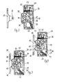
- eine Verriegelungsvorrichtung in einer Perspektivansicht ihrer auseinander gezogen dargestellten Einzelteile,
- Fig. 2
- die Verriegelungseinrichtung gemäß Figur 1 im Zusammenbau in der Öffnungsstellung ihrer Schließfalle,
- Fig. 3
- die Verriegelungseinrichtung gemäß Figur 2 in der Verriegelungsstellung bei blockierter Schließfalle,
- Fig. 4
- die Verriegelungseinrichtung gemäß Figur 2 beziehungsweise 3 in der Verriegelungsstellung bei bestehender Öffnungsbereitschaft der Schließfalle.
- Fig. 1
- a locking device in a perspective view of its exploded parts,
- Fig. 2
- the locking device according to Figure 1 in the assembly in the open position of its latch,
- Fig. 3
- 2 in the locking position when the locking latch is locked,
- Fig. 4
- the locking device according to Figure 2 or 3 in the locking position in the case of existing opening readiness of the closing latch.
Die aus Figur 1 ersichtliche Verriegelungseinrichtung besteht zunächst aus einem an einer nicht dargestellten Tür eines insbesondere Schaltschrankes anzubringenden Verschlusshalter 10, der einen Sperrstift 11 trägt.The apparent from Figure 1 locking device consists initially of a not shown on a door of a particular cabinet to be mounted
An dem ebenfalls nicht dargestellten Schrankkorpus des betreffenden Schaltschrankes ist ein Schloss 12 befestigbar, welches aus zwei Gehäusehälften 13 besteht. Im Inneren des Gehäuses ist eine Schließfalle 14 um einen gehäusefesten Lagerzapfen 15 drehbar angeordnet, die eine Aufnahmeöffnung 16 für den Sperrstift 11 aufweist. Die Schließfalle 14 ist dabei in dem Gehäuse 13 derart angeordnet, dass in der noch zu erläuternden Öffnungsstellung der Schließfalle der Sperrstift 11 des Verschlusshalters 10 in die Aufnahmeöffnung 16 der Schließfalle 14 einführbar ist, während in der Verriegelungsstellung die Schließfalle 14 den Sperrstift 11 in ihrer Aufnahmeöffnung 16 festhält. Die Schließfalle 14 ist hierzu von einer Kippfeder 17 beaufschlagt, die die Schließfalle 14 sowohl in ihre Öffnungsstellung wie auch in ihre Verriegelungsstellung vorspannt und hierbei einen Totpunkt durchschreitet. In den beiden Endstellungen ist die Kippfeder 17 durch Gehäuseanschläge 18 in einer definierten Stellung gehalten. Aufgrund der Vorspannung durch die Kippfeder 17 ergibt sich eine Rastwirkung für die Schließfalle 14 in deren beiden Endstellungen.At the also not shown cabinet body of the relevant cabinet, a
In dem Gehäuse 13 des Schlosses 12 ist ferner ein Sicherungshebel 19 um einen Lagerstift 22 drehbar gelagert, der an seinem der Schließfalle 14 zugewandten Ende eine Blockiernase 20 aufweist, während an seinem bezüglich des Lagerstiftes 22 gegenüberliegenden Ende ein Betätigungsansatz 21 vorhanden ist. Im Bereich des Betätigungsansatzes 21 greift eine sich am Gehäuse abstützende Feder 23 an, die den Sicherungshebel 19 in seine Blockierstellung für die Schließfalle 14 vorspannt, in welcher der Betätigungsansatz 21 in Eingriff mit einer an der Außenseite der Schließfalle 14 eingerichteten Blockierausnehmung 28 steht. Weiterhin ist dem Betätigungsansatz 21 ein Elektromagnet 24 zugeordnet, der in bestromtem Zustand den Betätigungsansatz 21 an sich heranzieht und dadurch den Sicherungshebel 19 entgegen der Wirkung der Feder 23 in eine Freigabe-stellung für die Schließfalle schwenkt.In the
Zusätzlich ist im Gehäuse 13 noch ein Mikroschalter 25 derart angeordnet, dass der Mikroschalter 25 von einem an der Schließfalle 14 befindlichen Exzenteransatz 30 in der Öffnungsstellung der Schließfalle betätigt wird. Der Mikroschalter 25 ist über eine elektrische Zuleitung 26 mit einem außerhalb des Gehäuses angeordneten Stecker 27 verbunden, so dass an dem Stecker 27 das vom Mikroschalter 25 bei seiner Schaltung abgegebenen Signal abgreifbar ist.In addition, a
In der in Figur 2 dargestellten Funktionsstellung befindet sich die Schließfalle 14 in ihrer Öffnungsstellung, in welcher die offene Seite ihrer Aufnahmeöffnung 16 dem Verschlusshalter 10 mit Sperrstift 11 zugewandt ist. In dieser Stellung ist die Schließfalle 14 durch die Kippfeder 17 gehalten. Gleichzeitig betätigt der Exzenteransatz 30 den Mikroschalter 25, so dass an dem Stecker 27 ein Signal abgreifbar ist, dass sich die Schließfalle 14 in der Öffnungsstellung befindet, so dass die Tür mit dem daran befestigten Verschlusshalter geschlossen werden kann. Dies kann beispielsweise durch Anzeige einer grünen Lampe geschehen.In the functional position shown in Figure 2, the
Wird nun die Tür durch Heranführen des Verschlusshalters 10 an das Schloss 12 geschlossen, so greift der Sperrstift 11 in die Aufnahmeöffnung 16 der Schließfalle 14 ein. Da die entsprechende Begrenzungsfläche der Aufnahmeöffnung 16 so ausgebildet ist, dass der auf diese Fläche drückende Sperrstift 11 die Schließfalle 14 in deren in Figur 2 dargestellte Schließstellung beaufschlagt, dreht sich die Schließfalle 14 in die in Figur 2 dargestellte Lage, wobei diese Drehung durch das Wandern der Kippfeder 17 von der einen Endstellung in die in Figur 3 dargestellte Endstellung unterstützt wird, in welcher die Kippfeder 17 die Schließfalle 14 in der Schließstellung rastend hält. Bei dieser Bewegung gleitet die Blockiernase 20 des Sicherungshebels 19 an der Außenseite der Schließfalle 14 entlang und rastet unter dem Druck der Feder 23 in die Blockierausnehmung 28 der Schließfalle 14 ein, in welcher die Blockiernase 20 gegen den die Blockierausnehmung 28 begrenzenden Absatz 29 anliegt und eine Rückdrehung der Schließfalle 14 auch bei einem entsprechenden Zug am Verschlusshalter 10 verhindert. In dieser Stellung ist das Schloss 12 mit dem Verschlusshalter 10 sicher verriegelt; eine Öffnung ist nicht möglich.Now, if the door is closed by bringing the
Soll nun die Verriegelungseinrichtung geöffnet werden, so wird der Elektromagnet 24 bestromt, der dadurch den Sicherungshebel 19 in die in Figur 4 dargestellte Lage verschwenkt, in welcher nun die Blockiernase 20 aus der Blockierausnehmung 28 soweit herausgerutscht ist, dass bei einer Drehung der Schließfalle 14 in die Öffnungsstellung (Figur 2) der Absatz 29 an der Blockiernase 20 des Sicherungshebels 19 vorbeigehen kann. Somit wird über die Bestromung des Elektromagneten 24 zunächst nur eine Öffnungsbereitschaft der Schließfalle 24 eingestellt, in welcher es eines Ziehens an dem Verschlusshalter 10 beziehungsweise an der diesen tragenden Tür bedarf, um nun entgegen der Kraft der Kippfeder 17 die Schließfalle in ihre aus Figur 2 ersichtliche Öffnungsstellung zu verschwenken.If now the locking device to be opened, the
Die in der vorstehenden Beschreibung, den Patentansprüchen, der Zusammenfassung und der Zeichnung offenbarten Merkmale des Gegenstandes dieser Unterlagen können einzeln als auch in beliebigen Kombinationen untereinander für die Verwirklichung der Erfindung in ihren verschiedenen Ausführungsformen wesentlich sein.The features disclosed in the foregoing description, the claims, the abstract and the drawings of the subject matter of these documents may be essential individually as well as in any combination with each other for the realization of the invention in its various embodiments.
Claims (5)
Applications Claiming Priority (1)
| Application Number | Priority Date | Filing Date | Title |
|---|---|---|---|
| DE200620015093 DE202006015093U1 (en) | 2006-09-30 | 2006-09-30 | One point locking device for switch cabinets has lock, switch bolt and locking pin pre-tensioned using rocker spring, security lever to block turning movement of switch bolt pivotable by electro-magnet force |
Publications (2)
| Publication Number | Publication Date |
|---|---|
| EP1908902A2 true EP1908902A2 (en) | 2008-04-09 |
| EP1908902A3 EP1908902A3 (en) | 2011-07-06 |
Family
ID=37545561
Family Applications (1)
| Application Number | Title | Priority Date | Filing Date |
|---|---|---|---|
| EP20070017522 Withdrawn EP1908902A3 (en) | 2006-09-30 | 2007-09-07 | Single-point bolting device in particular for switching cabinets |
Country Status (3)
| Country | Link |
|---|---|
| US (1) | US20080087054A1 (en) |
| EP (1) | EP1908902A3 (en) |
| DE (1) | DE202006015093U1 (en) |
Families Citing this family (3)
| Publication number | Priority date | Publication date | Assignee | Title |
|---|---|---|---|---|
| US9915082B2 (en) | 2014-11-07 | 2018-03-13 | Southco, Inc. | Cam latch |
| WO2021195516A1 (en) * | 2020-03-27 | 2021-09-30 | Home Valet, Inc. | Apparatus to allow for storage or holding of items, especially for deliveries and/or pickups |
| US20240209656A1 (en) * | 2021-04-08 | 2024-06-27 | Southco, Inc. | Latch system with actuator, position sensor, or actuator and position sensor |
Family Cites Families (9)
| Publication number | Priority date | Publication date | Assignee | Title |
|---|---|---|---|---|
| US1899234A (en) * | 1932-03-16 | 1933-02-28 | Werth Charles Harold De | Closure fastener operator |
| DE3301636A1 (en) * | 1983-01-19 | 1984-07-19 | Bosch-Siemens Hausgeräte GmbH, 7000 Stuttgart | LOCKING DEVICE FOR THE DOOR OF ELECTRICAL HOUSEHOLD APPLIANCES |
| DE19600524B4 (en) * | 1995-12-20 | 2006-07-06 | Siemens Ag | Lock, in particular for motor vehicle doors |
| US6279361B1 (en) * | 1995-12-20 | 2001-08-28 | Vdo Adolf Schindling Ag | Lock in particular for motor vehicle doors |
| DE29806963U1 (en) * | 1998-04-17 | 1998-07-02 | Emka Beschlagteile Gmbh & Co Kg, 42551 Velbert | Cam lock |
| DE19943483B4 (en) * | 1999-09-10 | 2008-03-06 | Kiekert Ag | Motor vehicle door lock |
| ITTO20020182A1 (en) * | 2002-03-05 | 2003-09-05 | Itw Ind Components Srl | CLOSING DEVICE FOR THE DOOR OF A HOUSEHOLD APPLIANCE, IN PARTICULAR OF A DISHWASHER. |
| DE10350710B4 (en) * | 2003-10-30 | 2021-01-07 | Marquardt Gmbh | Closure for a household appliance |
| DE102004033735B4 (en) * | 2004-07-13 | 2006-07-27 | Huf Hülsbeck & Fürst Gmbh & Co. Kg | Device for actuating locks on doors or flaps of vehicles |
-
2006
- 2006-09-30 DE DE200620015093 patent/DE202006015093U1/en not_active Expired - Lifetime
-
2007
- 2007-09-07 EP EP20070017522 patent/EP1908902A3/en not_active Withdrawn
- 2007-09-28 US US11/904,770 patent/US20080087054A1/en not_active Abandoned
Also Published As
| Publication number | Publication date |
|---|---|
| DE202006015093U1 (en) | 2006-11-30 |
| EP1908902A3 (en) | 2011-07-06 |
| US20080087054A1 (en) | 2008-04-17 |
Similar Documents
| Publication | Publication Date | Title |
|---|---|---|
| DE69819234T2 (en) | padlock | |
| DE202012007145U1 (en) | Retractable push-button element for a lockable or lockable furniture part | |
| DE10194835B4 (en) | lever lock | |
| DE69207320T2 (en) | Improved lock with a device for opening in an emergency | |
| EP3016844B1 (en) | Lock assembly for luggage case | |
| DE3328284C2 (en) | Lock for suitcases equipped with permutation lock | |
| EP1908902A2 (en) | Single-point bolting device in particular for switching cabinets | |
| DE19643370A1 (en) | Snap pawl with a toggle with overhead pivot and a built-in switch | |
| WO2012049127A1 (en) | Lock | |
| EP3091151B1 (en) | Driving rod lock for a driving rod fitting | |
| WO2008019844A1 (en) | Lockable pin-type lock for sliding doors | |
| EP1862614A1 (en) | Lockable collapsible handle | |
| DE202015104480U1 (en) | Compact self-locking mortise lock | |
| DE10246643B4 (en) | Electromechanical lock with protection against incorrect operation | |
| DE202011106902U1 (en) | Insert part for security fitting | |
| DE2630019C3 (en) | Electrically operated lock, especially for valuables containers or the like | |
| EP0239855A1 (en) | Lock for a door, window, or the like | |
| WO2007104295A1 (en) | Door lock for a house or apartment door | |
| EP3216952B1 (en) | Locking device | |
| DE9207865U1 (en) | Anti-panic hotel lock operated by a key and/or a handle | |
| DE10048739C1 (en) | Olive, for operation of lock, has cylinder axis of lock cylinder provided with radial pin rotated through given angle for movement of locking bolt | |
| DE366427C (en) | Disc-shaped padlock | |
| DE533217C (en) | Fastening of cylinder locks | |
| CH608267A5 (en) | Blocking device for a door lock | |
| DE637766C (en) | Device for locking the printer |
Legal Events
| Date | Code | Title | Description |
|---|---|---|---|
| PUAI | Public reference made under article 153(3) epc to a published international application that has entered the european phase |
Free format text: ORIGINAL CODE: 0009012 |
|
| AK | Designated contracting states |
Kind code of ref document: A2 Designated state(s): AT BE BG CH CY CZ DE DK EE ES FI FR GB GR HU IE IS IT LI LT LU LV MC MT NL PL PT RO SE SI SK TR |
|
| AX | Request for extension of the european patent |
Extension state: AL BA HR MK RS |
|
| PUAL | Search report despatched |
Free format text: ORIGINAL CODE: 0009013 |
|
| AK | Designated contracting states |
Kind code of ref document: A3 Designated state(s): AT BE BG CH CY CZ DE DK EE ES FI FR GB GR HU IE IS IT LI LT LU LV MC MT NL PL PT RO SE SI SK TR |
|
| AX | Request for extension of the european patent |
Extension state: AL BA HR MK RS |
|
| 17P | Request for examination filed |
Effective date: 20111111 |
|
| GRAP | Despatch of communication of intention to grant a patent |
Free format text: ORIGINAL CODE: EPIDOSNIGR1 |
|
| STAA | Information on the status of an ep patent application or granted ep patent |
Free format text: STATUS: THE APPLICATION HAS BEEN WITHDRAWN |
|
| AKX | Designation fees paid |
Designated state(s): DE |
|
| 18W | Application withdrawn |
Effective date: 20120303 |