EP1908913A1 - Verglasungsbefestigung - Google Patents
Verglasungsbefestigung Download PDFInfo
- Publication number
- EP1908913A1 EP1908913A1 EP06121779A EP06121779A EP1908913A1 EP 1908913 A1 EP1908913 A1 EP 1908913A1 EP 06121779 A EP06121779 A EP 06121779A EP 06121779 A EP06121779 A EP 06121779A EP 1908913 A1 EP1908913 A1 EP 1908913A1
- Authority
- EP
- European Patent Office
- Prior art keywords
- glazing
- sheet
- assembly
- laminated assembly
- synthetic material
- Prior art date
- Legal status (The legal status is an assumption and is not a legal conclusion. Google has not performed a legal analysis and makes no representation as to the accuracy of the status listed.)
- Withdrawn
Links
- 229920002994 synthetic fiber Polymers 0.000 claims abstract description 14
- 239000000463 material Substances 0.000 claims abstract description 9
- 229920005989 resin Polymers 0.000 claims description 23
- 239000011347 resin Substances 0.000 claims description 23
- 238000002347 injection Methods 0.000 claims description 4
- 239000007924 injection Substances 0.000 claims description 4
- 238000011065 in-situ storage Methods 0.000 claims description 2
- 238000009413 insulation Methods 0.000 claims description 2
- 239000007788 liquid Substances 0.000 claims description 2
- 239000011521 glass Substances 0.000 abstract description 26
- 125000006850 spacer group Chemical group 0.000 abstract description 3
- 239000003822 epoxy resin Substances 0.000 abstract 1
- 229920000647 polyepoxide Polymers 0.000 abstract 1
- 238000007789 sealing Methods 0.000 description 6
- 239000011324 bead Substances 0.000 description 5
- 239000011229 interlayer Substances 0.000 description 5
- 239000000853 adhesive Substances 0.000 description 2
- 238000004026 adhesive bonding Methods 0.000 description 2
- 230000001070 adhesive effect Effects 0.000 description 2
- XAGFODPZIPBFFR-UHFFFAOYSA-N aluminium Chemical compound [Al] XAGFODPZIPBFFR-UHFFFAOYSA-N 0.000 description 2
- 229910052782 aluminium Inorganic materials 0.000 description 2
- 238000000034 method Methods 0.000 description 2
- 229920002037 poly(vinyl butyral) polymer Polymers 0.000 description 2
- 229920000915 polyvinyl chloride Polymers 0.000 description 2
- 239000012858 resilient material Substances 0.000 description 2
- 239000004593 Epoxy Substances 0.000 description 1
- 230000032683 aging Effects 0.000 description 1
- 238000004873 anchoring Methods 0.000 description 1
- 230000000712 assembly Effects 0.000 description 1
- 238000000429 assembly Methods 0.000 description 1
- 125000000484 butyl group Chemical group [H]C([*])([H])C([H])([H])C([H])([H])C([H])([H])[H] 0.000 description 1
- 238000009833 condensation Methods 0.000 description 1
- 230000005494 condensation Effects 0.000 description 1
- 239000000470 constituent Substances 0.000 description 1
- 238000010276 construction Methods 0.000 description 1
- 230000032798 delamination Effects 0.000 description 1
- 230000001419 dependent effect Effects 0.000 description 1
- 238000006073 displacement reaction Methods 0.000 description 1
- 238000005553 drilling Methods 0.000 description 1
- 230000000694 effects Effects 0.000 description 1
- 239000005038 ethylene vinyl acetate Substances 0.000 description 1
- 239000000945 filler Substances 0.000 description 1
- 239000005340 laminated glass Substances 0.000 description 1
- 239000010410 layer Substances 0.000 description 1
- 239000013521 mastic Substances 0.000 description 1
- 229920000642 polymer Polymers 0.000 description 1
- 238000010008 shearing Methods 0.000 description 1
- 230000006641 stabilisation Effects 0.000 description 1
- 238000011105 stabilization Methods 0.000 description 1
- 230000035882 stress Effects 0.000 description 1
- 239000012815 thermoplastic material Substances 0.000 description 1
Images


Classifications
-
- E—FIXED CONSTRUCTIONS
- E06—DOORS, WINDOWS, SHUTTERS, OR ROLLER BLINDS IN GENERAL; LADDERS
- E06B—FIXED OR MOVABLE CLOSURES FOR OPENINGS IN BUILDINGS, VEHICLES, FENCES OR LIKE ENCLOSURES IN GENERAL, e.g. DOORS, WINDOWS, BLINDS, GATES
- E06B3/00—Window sashes, door leaves, or like elements for closing wall or like openings; Layout of fixed or moving closures, e.g. windows in wall or like openings; Features of rigidly-mounted outer frames relating to the mounting of wing frames
- E06B3/54—Fixing of glass panes or like plates
- E06B3/5436—Fixing of glass panes or like plates involving holes or indentations in the pane
Definitions
- the present invention relates to glass fixing techniques, including glazing constituting the outer walls of buildings.
- Exterior glazing is most often mounted without a frame. For aesthetic reasons in particular, the fixing of these windows is done by points by means of elements that connect them to the structure of buildings. These windows are commonly called “external glazing attached”.
- insulating glass units traditionally stability is ensured by the use of a frame.
- the sheets are held together by gluing also at the periphery, which can also contribute to the sealing of the space between the sheets.
- These windows also have a "spacer" located at their periphery to maintain the distance between the sheets.
- the invention proposes to provide insulating glazing units of the attached exterior glazing type, used on the building facade, in which the fastening means do not pass through the outer glass sheet.
- the invention also proposes insulating glazings in which the fastening means simultaneously ensure the spacing of the sheets.
- the invention also proposes insulating glazing units whose method of attachment does not require the use of complex mechanical means for adjusting the position of these means relative to the fixing locations on the glazing units concerned.
- the object of the invention is obtained by a glazing unit comprising at least one laminated assembly disposed towards the outside of the glazing, together associated with a sheet or other laminated assembly, the two being separated by a space filled with a gas contributing to the insulating properties of the glazing, glazing whose fixing is carried out by points distant from the periphery of the glazing without crossing the outermost sheet and, on the one hand which comprises a mechanical assembly holding the sheet, or the laminated assembly, constituting the element of the glazing located on the side of the structure on which the insulating glazing unit is fixed, and secondly which holds the exterior laminated assembly by a tenon of synthetic material cured, formed in situ in a hole of the sheet of the laminated assembly facing the gas-filled space, the synthetic material also filling a cavity of this space bounded around the fixing means.
- the mechanical assembly holding the sheet or the laminated assembly located on the side of the supporting structure is embedded in the cured synthetic material forming the tenon taken from the outer laminated assembly.
- This way adds to the strength of the assembly by transferring the pulling forces that could be exerted in a normal direction to the glazing plane on the connection between these mechanical means and the cured synthetic material.
- the resistance in this direction would be reduced to that resulting from the bonding of the hardened material with the face of the inner sheet and the elements carried by it.
- the fastening means do not pass through the entire glazing, it is preferable as well to obtain the best possible fixing as to facilitate the realization of these glazings, that in the outer laminated assembly, the inner sheet is pierced with a through hole in which the tenon is located.
- the cured synthetic material advantageously extends into housings, blind holes, grooves or the like located on the inner face of the outermost sheet. These dwellings are not crossing. They contribute to the stabilization of the glazing against any displacement of this outer sheet in the plane of the glazing.
- the mechanical assembly for fixing the sheet or laminated assembly located on the side of the supporting structure advantageously comprises a conduit through which the subsequently hardened synthetic material is injected in liquid form.
- the duct is advantageously extended into the recess of the outer laminate in which it is intended to form a tenon.
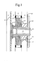
- the glazing shown in Figure 1 consists of an assembly comprising two sheets of glass (1 and 2), joined by means of a traditional interlayer (3).
- the interlayer is a sheet of a thermoplastic material such as polyvinyl butyral (PVB), ethylene vinyl acetate (EVA), polyvinylchlorides (PVC) or analogous materials traditionally used to form laminated glass.
- PVB polyvinyl butyral
- EVA ethylene vinyl acetate
- PVC polyvinylchlorides
- the glazing comprises a third glass sheet (4) arranged at a distance from the first.
- the laminate (1,2,3) and the glass sheet (4) are conventionally assembled at their periphery, not shown, by means of spacers arranged between the sheets and glued to them.
- the tightness of the space (5) delimited between the sheets is obtained by traditional sealing beads such as cords of butyl polymer mastic.
- each glazing attachment point The sealing and spacing are also maintained at the location of each glazing attachment point to accommodate the need for drilling.
- the sheet (4) is pierced with a through hole.
- the sealing and the spacing before implementation of the fixing are provided by means of a rigid ring (6) and adhesive beads (7, 8).
- the bead of adhesive is advantageously located in grooves formed in the walls of the ring (6).
- the glass sheet (4) is pierced with a through hole.
- the circular orifice has on its face facing the space between the sheets a frustoconical chamfer (9) in which is inserted a corresponding shaped ring (10).
- the ring (10) is dimensioned so that it corresponds substantially to the thickness of the sheet (4).
- a ring of a resilient material (not shown in FIGS. 1 and 2) which interposes between these walls and the ring. (10).
- the ring (10) is threaded to receive a sleeve (11).
- the sleeve (11) is threaded externally and internally.
- the assembly comprising the sleeve (11) and the ring (10) encloses the sheet (4), on the one hand by means of the ring (10) screwed on the sleeve, and secondly by means of the nut (12). If necessary the threaded ring (10) can be replaced by a ring whose opening is smooth. In this case a separate nut (not shown) holds the sleeve (11) on the side of the space between the sheets, the nut 12 is applied to the outer face of the sheet (4). It is not very compressible, but of relatively modest hardness (13), is interposed between the sheet (4) and the nut (12), advantageously an annealed aluminum washer is used.
- the glass sheet (2) also has a through orifice opposite that of the sheet (4).
- This orifice on the face of the sheet turned towards the inside of the laminate also comprises a frustoconical flare (14).
- the sleeve (11) allows the injection by a central duct (15) of a "curable” resin into the cavity (16) delimited, outside the sleeve (11) itself, by the glass sheets (1, 2,4), the ring (6) and the ring (10).
- One or more vents (17) formed in the ring (10) allow to evacuate the air expelled by the resin during the injection thereof.
- the filling is advantageously carried out. arranging the glazing in a horizontal plane, the laminated layer (1,2,3) being in the low position.
- the resin filling the cavity (16) is in contact with the glass sheet (1).
- the interlayer sheet (3) is preferably cut so that the glass sheet (1) is not covered by this insert in the portion facing the orifice made in the sheet (2). In this way the resin can adhere directly to the sheet (1) and contribute to the stability of the whole laminated. It is also possible to leave the interlayer over the entire face of the sheet (1) insofar as the material of the interlayer sheet is compatible with the injected resin.
- the sleeve adheres to the resin.
- the presence of its external thread taken in the resin considerably strengthens the resistance to the tensile forces exerted in the direction of the axis of the fastening means.
- the resin filling the frustoconical portion (14) of the orifice made in the sheet (2) forms a tenon which firmly secures the laminated glazing (1, 2, 3) and the glass sheet (4) by the intermediate of the sleeve.
- the proposed arrangement is not dependent on the quality of the adhesion proper of the resin to the various constituents in contact with it.
- the fastener holding the shape of the cavity filled with resin is also substantially insensitive to aging thereof, which would not necessarily be the case for a fixation that would be achieved by simple "gluing".
- the frustoconical portion of the ring (10) immobilizes the sleeve (11) relative to the sheet 4).
- the choice of the resin should lead to a particularly hardened material.
- Various known resins for assemblies can be used in particular epoxy type resins, optionally comprising fillers that enhance their strength.
- the sleeve (11) which partially engages in the hole drilled in the glass sheet (2), further adds to the mechanical strength against shear forces in the sheet plane.
- the hardening of the resin in the cavity (16) also contributes to the seal at these fastening means in addition to the action of the ring (6) and the sealing beads (7 and 8).
- the sleeve (11) is also threaded internally to receive a screw not shown.
- the screw in question is an intermediate of fixing with the structure of the building.
- the traditional laminates are generally sufficiently stable under the conditions of use to ensure the adhesion of the glass sheet (1) to the glass sheet (2), and that no risk of creep or "delamination” is to be obtained. to fear. Nevertheless, the weight of the large leaves exerts considerable forces on the vertical windows. To better resist the shearing forces exerted in the plane of the sheets, it may be advantageous to extend the cavity in which the resin is injected by one or more recesses, blind holes or grooves, made in the thickness of the sheet. of glass (1).
- FIG. 2 similar to the previous one, shows an embodiment comprising the extension of the introduction of the resin into the outermost sheet (1).
- a groove (18) which may take for example a circular shape is formed before assembly of the laminate in the sheet (1).
- This groove as the entire cavity (16) fills with resin. After hardening, the assembly is blocked in the plane of the sheets. In this case, even if the insert (3) may tend to deform, especially to lose rigidity under the influence of heat, for example, the risk of deformation of the glazing is well controlled.
- the depth of the recesses, grooves or blind holes (18) is not critical provided that they reserve a glass thickness to the outer surface sufficient to not weaken this surface. Furthermore, the presence of the resin in the groove, once it hardened, at least partially reconstitutes the initial strength of the reduced sheet by the presence of the groove.
- the fastening elements according to the invention unlike the means passing through all the sheets, do not constitute thermal bridges likely to cause the negative effects indicated above.
- Figure 3 shows a variant of the injection and fixing elements.
- the element (19) acts both as the ring (10) and the sleeve (11) of Figures 1 and 2.
- this element is held in the hole drilled in the glass sheet (4) by means of a nut (12) which is fixed on the external thread of the part of the element (19) projecting beyond the outer face of the sheet (4) (.
- the presence of the washer (13) prevents direct contact of the sheet (4) with the nut (12).
- a resilient material (21) is interposed between the element (19) and the walls of the hole of the glass sheet (4).
- This arrangement is not specific to the embodiment of FIG. 3. It can be implemented both in the modes of FIGS. 1 and 2.
- the material of (21) is advantageously, for example, annealed aluminum which exhibits good crush resistance without its relative hardness leading to glass breakage primers when clamping the element (19) by means of the nut (13).
- a tube (20) provided with a flange is arranged in the central part of the element (19), in an axial position relative to this element.
- the tube (20), threaded externally, is screwed into the corresponding thread of the element (19).
- the end of the tube (20) contributes, as previously sleeve (11), anchoring the fastening means in the hardened resin block which fills the cavity (16).
- the fastening means to the building structure are screwed into the threaded central portion (22) of the element (19).
- the assembly is carried out as before.
Landscapes
- Engineering & Computer Science (AREA)
- Civil Engineering (AREA)
- Structural Engineering (AREA)
- Securing Of Glass Panes Or The Like (AREA)
Priority Applications (1)
| Application Number | Priority Date | Filing Date | Title |
|---|---|---|---|
| EP06121779A EP1908913A1 (de) | 2006-10-05 | 2006-10-05 | Verglasungsbefestigung |
Applications Claiming Priority (1)
| Application Number | Priority Date | Filing Date | Title |
|---|---|---|---|
| EP06121779A EP1908913A1 (de) | 2006-10-05 | 2006-10-05 | Verglasungsbefestigung |
Publications (1)
| Publication Number | Publication Date |
|---|---|
| EP1908913A1 true EP1908913A1 (de) | 2008-04-09 |
Family
ID=37697943
Family Applications (1)
| Application Number | Title | Priority Date | Filing Date |
|---|---|---|---|
| EP06121779A Withdrawn EP1908913A1 (de) | 2006-10-05 | 2006-10-05 | Verglasungsbefestigung |
Country Status (1)
| Country | Link |
|---|---|
| EP (1) | EP1908913A1 (de) |
Cited By (1)
| Publication number | Priority date | Publication date | Assignee | Title |
|---|---|---|---|---|
| US10562274B1 (en) * | 2016-02-22 | 2020-02-18 | Apple Inc. | Glass fastening and sealing systems |
Citations (3)
| Publication number | Priority date | Publication date | Assignee | Title |
|---|---|---|---|---|
| EP0340089A1 (de) * | 1988-04-28 | 1989-11-02 | Saint-Gobain Vitrage International | Verglasungselement für Vorhangfassaden |
| EP0506522A1 (de) * | 1991-03-29 | 1992-09-30 | Saint-Gobain Vitrage | Befestigungssystem |
| WO2002002899A1 (fr) * | 2000-07-06 | 2002-01-10 | Saint-Gobain Glass France | Dispositif de fixation pour un element de paroi feuillete |
-
2006
- 2006-10-05 EP EP06121779A patent/EP1908913A1/de not_active Withdrawn
Patent Citations (3)
| Publication number | Priority date | Publication date | Assignee | Title |
|---|---|---|---|---|
| EP0340089A1 (de) * | 1988-04-28 | 1989-11-02 | Saint-Gobain Vitrage International | Verglasungselement für Vorhangfassaden |
| EP0506522A1 (de) * | 1991-03-29 | 1992-09-30 | Saint-Gobain Vitrage | Befestigungssystem |
| WO2002002899A1 (fr) * | 2000-07-06 | 2002-01-10 | Saint-Gobain Glass France | Dispositif de fixation pour un element de paroi feuillete |
Cited By (3)
| Publication number | Priority date | Publication date | Assignee | Title |
|---|---|---|---|---|
| US10562274B1 (en) * | 2016-02-22 | 2020-02-18 | Apple Inc. | Glass fastening and sealing systems |
| US11141950B1 (en) | 2016-02-22 | 2021-10-12 | Apple Inc. | Glass fastening and sealing systems |
| US11772354B1 (en) | 2016-02-22 | 2023-10-03 | Apple Inc. | Glass fastening and sealing systems |
Similar Documents
| Publication | Publication Date | Title |
|---|---|---|
| EP0340089B1 (de) | Verglasungselement für Vorhangfassaden | |
| EP1297237B1 (de) | Befestigungsvorrichtung für ein mehrschichtiges wandelement | |
| EP1204803B1 (de) | Befestigungsvorrichtung einer verbundglasscheibe | |
| EP0533566B1 (de) | Befestigungseinrichtung für vorgebohrte Glasscheiben | |
| WO2006070159A1 (fr) | Vitre de fenetre avec un element de securite | |
| EP1106342B1 (de) | Verbundglasscheibe für eine Glasstruktur | |
| EP1711341B1 (de) | Einheit enthaltend verbundglässer | |
| FR2927113A1 (fr) | Ouvrants dans le domaine de la menuiserie | |
| EP4401996B1 (de) | System zur befestigung einer seitenverglasung eines transportmittels mit einem schloss mit mindestens einer verwechslungssicherungsprojektion | |
| EP1537983A1 (de) | Einrichtung für ein Loch in einer Platte und so eingerichtete Platte | |
| EP3670810B1 (de) | Verglasungspaneel | |
| BE1000298A5 (fr) | Vitre et dispositif pour sa fixation a un support. | |
| EP2142742A1 (de) | Isolationsglasierungselement | |
| EP3468792B1 (de) | Brandschutzverglasung | |
| WO2023152256A1 (fr) | Ensemble vitré pour un aéronef, procédé de fabrication d'un tel ensemble vitré, et aéronef comprenant un tel ensemble vitré | |
| BE1013037A3 (fr) | Vitrage feuillete de securite. | |
| EP1443171A1 (de) | Dichtungsanordnung für eine Schliessanordnung einer Öffnung mit wenigstens einer Schiebetür | |
| EP1991752B1 (de) | Anordnung aus einer mehrfachverglasungseinheit und einem profil sowie profil für eine verglasungseinheit | |
| EP0859112B1 (de) | Fenster oder Tür mit einer dünnen Hochleistungsisolierverglasung | |
| EP2003279B1 (de) | Klappfenster oder Ähnliches mit Rahmen, mit verdecktem Öffnungsflügel | |
| FR2783865A1 (fr) | Element d'embrasure | |
| EP0887484A1 (de) | Fassade, insbesondere eine Glasfassade | |
| FR2964137A1 (fr) | Dormant de trappe de plafond | |
| FR2847297A1 (fr) | Fenetre a vitrage colle, presentant une resistance amelioree a la dilatation differentielle entre le vitrage et le cadre | |
| LU101145A1 (fr) | Procédé et kit pour le placement d'éléments de façade |
Legal Events
| Date | Code | Title | Description |
|---|---|---|---|
| PUAI | Public reference made under article 153(3) epc to a published international application that has entered the european phase |
Free format text: ORIGINAL CODE: 0009012 |
|
| AK | Designated contracting states |
Kind code of ref document: A1 Designated state(s): AT BE BG CH CY CZ DE DK EE ES FI FR GB GR HU IE IS IT LI LT LU LV MC NL PL PT RO SE SI SK TR |
|
| AX | Request for extension of the european patent |
Extension state: AL BA HR MK RS |
|
| 17P | Request for examination filed |
Effective date: 20080417 |
|
| 17Q | First examination report despatched |
Effective date: 20080626 |
|
| AKX | Designation fees paid |
Designated state(s): AT BE BG CH CY CZ DE DK EE ES FI FR GB GR HU IE IS IT LI LT LU LV MC NL PL PT RO SE SI SK TR |
|
| RAP1 | Party data changed (applicant data changed or rights of an application transferred) |
Owner name: AGC GLASS EUROPE |
|
| STAA | Information on the status of an ep patent application or granted ep patent |
Free format text: STATUS: THE APPLICATION HAS BEEN WITHDRAWN |
|
| 18W | Application withdrawn |
Effective date: 20140304 |