EP1908931A1 - Motorabgasreinigungsvorrichtung - Google Patents
Motorabgasreinigungsvorrichtung Download PDFInfo
- Publication number
- EP1908931A1 EP1908931A1 EP06766538A EP06766538A EP1908931A1 EP 1908931 A1 EP1908931 A1 EP 1908931A1 EP 06766538 A EP06766538 A EP 06766538A EP 06766538 A EP06766538 A EP 06766538A EP 1908931 A1 EP1908931 A1 EP 1908931A1
- Authority
- EP
- European Patent Office
- Prior art keywords
- abnormality
- concentration
- exhaust gas
- aqueous solution
- detected
- Prior art date
- Legal status (The legal status is an assumption and is not a legal conclusion. Google has not performed a legal analysis and makes no representation as to the accuracy of the status listed.)
- Granted
Links
Images


Classifications
-
- F—MECHANICAL ENGINEERING; LIGHTING; HEATING; WEAPONS; BLASTING
- F01—MACHINES OR ENGINES IN GENERAL; ENGINE PLANTS IN GENERAL; STEAM ENGINES
- F01N—GAS-FLOW SILENCERS OR EXHAUST APPARATUS FOR MACHINES OR ENGINES IN GENERAL; GAS-FLOW SILENCERS OR EXHAUST APPARATUS FOR INTERNAL-COMBUSTION ENGINES
- F01N3/00—Exhaust or silencing apparatus having means for purifying, rendering innocuous, or otherwise treating exhaust
- F01N3/08—Exhaust or silencing apparatus having means for purifying, rendering innocuous, or otherwise treating exhaust for rendering innocuous
- F01N3/10—Exhaust or silencing apparatus having means for purifying, rendering innocuous, or otherwise treating exhaust for rendering innocuous by thermal or catalytic conversion of noxious components of exhaust
- F01N3/18—Exhaust or silencing apparatus having means for purifying, rendering innocuous, or otherwise treating exhaust for rendering innocuous by thermal or catalytic conversion of noxious components of exhaust characterised by methods of operation; Control
- F01N3/20—Exhaust or silencing apparatus having means for purifying, rendering innocuous, or otherwise treating exhaust for rendering innocuous by thermal or catalytic conversion of noxious components of exhaust characterised by methods of operation; Control specially adapted for catalytic conversion
- F01N3/206—Adding periodically or continuously substances to exhaust gases for promoting purification, e.g. catalytic material in liquid form, NOx reducing agents
- F01N3/2066—Selective catalytic reduction [SCR]
-
- B—PERFORMING OPERATIONS; TRANSPORTING
- B01—PHYSICAL OR CHEMICAL PROCESSES OR APPARATUS IN GENERAL
- B01D—SEPARATION
- B01D53/00—Separation of gases or vapours; Recovering vapours of volatile solvents from gases; Chemical or biological purification of waste gases, e.g. engine exhaust gases, smoke, fumes, flue gases, aerosols
- B01D53/34—Chemical or biological purification of waste gases
- B01D53/74—General processes for purification of waste gases; Apparatus or devices specially adapted therefor
- B01D53/86—Catalytic processes
- B01D53/90—Injecting reactants
-
- B—PERFORMING OPERATIONS; TRANSPORTING
- B01—PHYSICAL OR CHEMICAL PROCESSES OR APPARATUS IN GENERAL
- B01D—SEPARATION
- B01D53/00—Separation of gases or vapours; Recovering vapours of volatile solvents from gases; Chemical or biological purification of waste gases, e.g. engine exhaust gases, smoke, fumes, flue gases, aerosols
- B01D53/34—Chemical or biological purification of waste gases
- B01D53/92—Chemical or biological purification of waste gases of engine exhaust gases
- B01D53/94—Chemical or biological purification of waste gases of engine exhaust gases by catalytic processes
- B01D53/9404—Removing only nitrogen compounds
- B01D53/9409—Nitrogen oxides
- B01D53/9431—Processes characterised by a specific device
-
- F—MECHANICAL ENGINEERING; LIGHTING; HEATING; WEAPONS; BLASTING
- F02—COMBUSTION ENGINES; HOT-GAS OR COMBUSTION-PRODUCT ENGINE PLANTS
- F02D—CONTROLLING COMBUSTION ENGINES
- F02D41/00—Electrical control of supply of combustible mixture or its constituents
- F02D41/02—Circuit arrangements for generating control signals
- F02D41/14—Introducing closed-loop corrections
- F02D41/1438—Introducing closed-loop corrections using means for determining characteristics of the combustion gases; Sensors therefor
- F02D41/1444—Introducing closed-loop corrections using means for determining characteristics of the combustion gases; Sensors therefor characterised by the characteristics of the combustion gases
- F02D41/146—Introducing closed-loop corrections using means for determining characteristics of the combustion gases; Sensors therefor characterised by the characteristics of the combustion gases the characteristics being an NOx content or concentration
- F02D41/1461—Introducing closed-loop corrections using means for determining characteristics of the combustion gases; Sensors therefor characterised by the characteristics of the combustion gases the characteristics being an NOx content or concentration of the exhaust gases emitted by the engine
- F02D41/1462—Introducing closed-loop corrections using means for determining characteristics of the combustion gases; Sensors therefor characterised by the characteristics of the combustion gases the characteristics being an NOx content or concentration of the exhaust gases emitted by the engine with determination means using an estimation
-
- B—PERFORMING OPERATIONS; TRANSPORTING
- B01—PHYSICAL OR CHEMICAL PROCESSES OR APPARATUS IN GENERAL
- B01D—SEPARATION
- B01D2251/00—Reactants
- B01D2251/20—Reductants
- B01D2251/206—Ammonium compounds
- B01D2251/2067—Urea
-
- F—MECHANICAL ENGINEERING; LIGHTING; HEATING; WEAPONS; BLASTING
- F01—MACHINES OR ENGINES IN GENERAL; ENGINE PLANTS IN GENERAL; STEAM ENGINES
- F01N—GAS-FLOW SILENCERS OR EXHAUST APPARATUS FOR MACHINES OR ENGINES IN GENERAL; GAS-FLOW SILENCERS OR EXHAUST APPARATUS FOR INTERNAL-COMBUSTION ENGINES
- F01N2610/00—Adding substances to exhaust gases
- F01N2610/02—Adding substances to exhaust gases the substance being ammonia or urea
-
- F—MECHANICAL ENGINEERING; LIGHTING; HEATING; WEAPONS; BLASTING
- F01—MACHINES OR ENGINES IN GENERAL; ENGINE PLANTS IN GENERAL; STEAM ENGINES
- F01N—GAS-FLOW SILENCERS OR EXHAUST APPARATUS FOR MACHINES OR ENGINES IN GENERAL; GAS-FLOW SILENCERS OR EXHAUST APPARATUS FOR INTERNAL-COMBUSTION ENGINES
- F01N2610/00—Adding substances to exhaust gases
- F01N2610/14—Arrangements for the supply of substances, e.g. conduits
- F01N2610/1406—Storage means for substances, e.g. tanks or reservoirs
-
- Y—GENERAL TAGGING OF NEW TECHNOLOGICAL DEVELOPMENTS; GENERAL TAGGING OF CROSS-SECTIONAL TECHNOLOGIES SPANNING OVER SEVERAL SECTIONS OF THE IPC; TECHNICAL SUBJECTS COVERED BY FORMER USPC CROSS-REFERENCE ART COLLECTIONS [XRACs] AND DIGESTS
- Y02—TECHNOLOGIES OR APPLICATIONS FOR MITIGATION OR ADAPTATION AGAINST CLIMATE CHANGE
- Y02T—CLIMATE CHANGE MITIGATION TECHNOLOGIES RELATED TO TRANSPORTATION
- Y02T10/00—Road transport of goods or passengers
- Y02T10/10—Internal combustion engine [ICE] based vehicles
- Y02T10/12—Improving ICE efficiencies
Definitions
- the present invention relates to an exhaust gas purifying apparatus for an engine, and more specifically to a technology for purifying nitrogen oxide discharged from an engine using ammonia as a reducing agent.
- NOx nitrogen oxide
- SCR Selective Catalytic Reduction
- Patent Document 1 Japanese Laid-Open (Kokai) Patent Application Publication No. 2000-027627 (paragraph number 0013)
- urea aqueous solution tank capable of storing therein the urea aqueous solution
- concentration of urea hereinafter when just "concentration” is mentioned, the concentration of urea shall be referred to
- a urea sensor there has been developed a type in which a heater and a temperature measuring resistor are equipped with and an actual concentration is determined based on an electric resistance value obtained by the temperature measuring resistor heated by the heater, by paying attention to the heat transmission characteristic of urea aqueous solution depending on the concentration ( Japanese Laid-Open (Kokai) Patent Application No. 2005-030888 (paragraph number 0044)).
- This inventor has disclosed an exhaust gas purifying apparatus for an engine which adopts a temperature-sensitive type urea sensor in Japanese Patent Application No. 2003-366737 (Japanese Laid-Open (Kokai) Patent Application Publication No. 2005-133541).
- the concentration detected by a urea sensor when the concentration detected by a urea sensor is lower than the normal range of concentration, it is estimated that water or other aqueous solution than urea aqueous solution of a predetermined concentration is stored in the urea aqueous solution tank, and then a further detection is performed to become aware of an abnormality about the concentration and some measures such as stopping of injection of urea aqueous solution is resultantly taken.
- a tank heater is provided in order to prevent urea aqueous solution from being frozen within the urea aqueous solution tank or unfreeze the frozen urea aqueous solution quickly, particularly, on an assumption that the apparatus is used in a cold district ( Japanese Laid-Open (Kokai) Patent Application Publication No. 2004-194028 ).
- the temperature-sensitive type concentration sensor upon adopting the temperature-sensitive type concentration sensor, it is demanded to have a capability of avoiding erroneous detection of abnormality originating from convection of aqueous solution in a storage tank and prevent malfunction of the exhaust gas purifying apparatus, such as unexpected stopping of addition of a reducing agent.
- the present invention was made in view of the above-described problems and is configured to adopt the concentration positively when the temperature of aqueous solution such as urea aqueous solution is maintained in an equilibrium state.
- the exhaust gas purifying apparatus for the engine of the present invention reduces NOx in an exhaust gas from an engine by adding a reducing agent for NOx to the exhaust gas and includes: a storage tank for storing the reducing agent for NOx or a precursor thereof to be added to the exhaust gas in the state of aqueous solution; a concentration detecting unit for detecting the concentration of the reducing agent or the precursor contained in the aqueous solution stored in the storage tank; and a control unit which detects a predetermined abnormality concerning the aqueous solution based on the concentration detected by the concentration detecting unit.
- the concentration detecting unit has a property such that an electric characteristic value thereof changes depending on the temperature and is configured to include therein a first temperature sensing body arranged to be in direct or indirect contact with the aqueous solution and a heater thermally connected to the first temperature sensing body.
- the concentration detecting unit drives the heater and outputs an electric characteristic value obtained by the first temperature sensing body heated by the heater as the concentration of the reducing agent or its precursor.
- the control unit determines whether or not the temperature of the aqueous solution is substantially in an equilibrium state and adopts, as basic information for detecting abnormality, the concentration detected at a time period of temperature equilibrium during which it is determined that the temperature of the aqueous solution is in the equilibrium state.
- the exhaust gas purifying apparatus is provided with a configuration such that determination is made as to whether or not the temperature of aqueous solution such as urea aqueous solution is substantially in an equilibrium state and the concentration obtained at the time of determination of the equilibrium state of the urea aqueous solution is adopted as basic information for detecting an abnormality. Consequently, erroneous detection of an abnormality originating from convection can be avoided to reflect a result of accurate abnormality detection in the operation of the exhaust gas purifying apparatus.
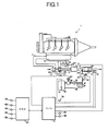
- FIG. 1 shows the structure of an automobile engine (hereinafter referred to as "engine") 1 according to an embodiment of the present invention.
- engine an automobile engine
- This embodiment adopts a direct fuel-injection diesel engine as the engine 1.
- An air cleaner (not shown) is provided on the introducing portion of a suction air passage 11 so as to deprive dust of suction air with this air cleaner.
- a compressor 12a of a variable nozzle type turbo charger 12 is provided in the suction air passage 11, and suction air is compressed by the compressor 12a to be delivered therefrom. The compressed suction air then flows into a surge tank 13 and is distributed to each cylinder through a manifold portion.
- injector 21 In an engine main body, its cylinder head is provided with injectors 21 at each cylinder.
- the injector 21 is operated according to a signal from an engine control unit (hereinafter referred to as "engine C/U") 51.
- Engine C/U engine control unit
- Fuel delivered from a fuel pump (not shown) is supplied to the injector 21 through a common rail 22 and injected into a combustion chamber from the injector 21.
- a turbine 12b of the turbo charger 12 is provided in the downstream of a manifold portion in the exhaust gas passage 31.
- the compressor 12a is rotated.
- a movable vane 121 of the turbine 12b is connected to an actuator 122 and its angle is controlled by the actuator 122.
- Oxidation catalyst 32, NOx purifying catalyst 33 and ammonia catalyst 34 are disposed in the downstream of the turbine 12b in this order from the upstream side.
- the oxidation catalyst 32 oxidizes carbon hydride and carbon monoxide in exhaust gas and converts nitric monoxide (hereinafter referred to as "NO") in the exhaust gas to NOx mainly composed of nitrogen dioxide (hereinafter referred to as “NO 2 "), exerting an operation of adjusting a ratio between NO and NO 2 contained in the exhaust gas to be suitable for reduction reaction of NOx described later.
- NOx purifying catalyst 33 purifies NOx by reducing NOx.
- ammonia is added to exhaust gas as a reducing agent in the upstream of the NOx purifying catalyst 33.
- urea which is a precursor of ammonia is stored in a state of aqueous solution. By storing ammonia in the form of urea, the safety is secured.
- a urea aqueous solution supply pipe 42 is connected to a storage tank 41 which stores urea aqueous solution and a urea aqueous solution injection nozzle 43 is mounted at the front end of this urea aqueous solution supply pipe 42.
- a feed pump 44 and a filter 45 are provided on the urea aqueous solution supply pipe 42 in this order from the upstream.
- the feed pump 44 is driven by an electric motor 441.
- the electric motor 441 is controlled in terms of its revolution number by a signal from an SCR control unit (hereinafter referred to as "SCR-C/U") 61 so as to adjust the amount of injection of the feed pump 44.
- SCR-C/U SCR control unit
- a urea aqueous solution return pipe 46 is connected to the urea aqueous solution supply pipe 42 in the downstream of the filter 45.
- a pressure control valve 47 is provided on the urea aqueous solution return pipe 46 and constructed so that excessive urea aqueous solution of an amount exceeding a specified pressure is returned to the storage tank 41.
- the injection nozzle 43 is an air assist type injection nozzle, which is constituted of a main body 431 and a nozzle portion 432. While the urea aqueous solution supply pipe 42 is connected to the main body 431, an air supply pipe 48 for supplying air for assist is also connected thereto. The air supply pipe 48 is connected to an air tank not shown, from which an assist-purpose air is supplied.
- the nozzle portion 432 is provided such that it penetrates the side face of a casing for the NOx purifying catalyst 33 and the ammonia catalyst 34 in the upstream of the NOx purifying catalyst 33.
- An injection direction of the nozzle portion 432 is set in parallel to a flow of exhaust gas such that it is directed to the end face of the NOx purifying catalyst 33.
- urea in the injected urea aqueous solution is hydrolyzed by exhaust gas heat so as to produce ammonia.
- the generated ammonia acts as a reducing agent for NOx on the NOx purifying catalyst 33 so as to reduce NOx.
- the ammonia catalyst 34 is for purifying slip ammonia having passed the NOx purifying catalyst 33 without contributing to reduction of NOx. It is not preferable to discharge ammonia in a non-purified condition because of its irritating odor.
- Oxidation reaction of NO by the oxidation catalyst 32, hydrolysis reaction of urea, reduction reaction of NOx with the NOx purifying catalyst 33 and oxidation reaction of slip ammonia in the ammonia catalyst 34 are expressed by the following equations (1) through (4), respectively.
- the NOx purifying catalyst 33 and the ammonia catalyst 34 are contained in an integral casing, it is permissible to construct respective casings separately.
- the exhaust gas passage 31 is fluidly connected to the suction air passage 11 via an EGR tube 35.
- the EGR tube 35 is provided with an EGR valve 36.
- the EGR valve 36 is connected to the actuator 361 and the degree of opening thereof is controlled by the actuator 361.
- a temperature sensor 71 is provided between the oxidation catalyst 32 and the NOx purifying catalyst 33 in the exhaust gas passage 31 for detecting the temperature of exhaust gas before urea aqueous solution is added.
- a temperature sensor 72 for detecting the temperature of exhaust gas after reduction and a NOx sensor 73 for detecting the concentration of NOx contained in the exhaust gas after reduction are provided downstream of the ammonia catalyst 34, respectively.
- a urea sensor 74 for detecting the concentration of urea contained in urea aqueous solution and a temperature sensor 75 for detecting the temperature of urea aqueous solution are provided in the storage tank 41, respectively. In the meantime, the urea sensor 74 constitutes a "concentration detecting unit" of this embodiment.
- Detection signals from the temperature sensors 71, 72, the NOx sensor 73, the urea sensor 74 and the temperature sensor 75 are outputted to the SCR-C/U 61.
- the SCR-C/U 61 calculates and sets an optimum urea aqueous solution injection quantity according to the inputted signals and outputs an instruction or command signal corresponding to the set urea aqueous solution injection quantity to the injection nozzle 43.
- the SCR-C/U 61 outputs an operation signal to a concentration alarm lamp 91 and a remaining amount alarm lamp 92 provided on a control panel of a driver's seat.
- the SCR-C/U 61 is connected to an engine C/U 51 to be capable of conducting bi-directional communication therebetween, so that a detected urea concentration is outputted from the SCR-C/U 61 to the engine C/U 51.
- an ignition switch 52, a start switch 53, a crank angle sensor 54, a vehicle velocity sensor 55, an acceleration sensor 56 and the like are provided on the engine 1 side and thus, these detection signals are inputted to the engine C/U 51.
- the engine C/U 51 executes calculation of an engine revolution number Ne based on a signal inputted from the crank angle sensor 54.
- the engine C/U 51 outputs information necessary for injection control of urea aqueous solution such as fuel injection amount to the SCR-C/U 61.
- the SCR-C/U 61 constitutes a "control unit" of this embodiment of the present invention.
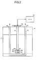
- FIG. 2 shows the structure of the urea sensor 74 and a relationship between the urea sensor 74 and a tank heater.
- the tank heater is constructed to contain a cooling water distribution pipe 81 which distributes cooling water of the engine 1.
- the cooling water distribution pipe 81 is bent in a U-shape and passes through the ceiling portion of the storage tank 41 at an inlet portion 81a and an outlet portion 81 b. Cooling water of the engine 1 after warm up of the engine is introduced into the cooling water distribution pipe 81 and the urea aqueous solution is heated with this cooling water used as heat medium.
- the urea sensor 74 is provided in the vicinity of the bottom portion of this U-shaped portion and surrounded by the cooling water distribution pipe 81 from three directions, namely, down, left and right (or front and rear).
- the urea sensor 74 has the same configuration as a flow rate/liquid type meter described in the above-described Japanese Laid-Open (Kokai) Patent Application Publication No. 2005-030888 and detects the concentration of urea based on electric characteristic values of two temperature sensing bodies.
- the flow rate/liquid type meter described in the above-described publication includes a first sensor device having a heater function and a second sensor device having no heater function.
- the first sensor device includes a heater layer and a temperature measuring resistive layer (hereinafter referred to as "first temperature measuring resistive layer”) as a temperature sensing body formed on the heater layer in an insulated state.
- the latter second sensor device includes the temperature measuring resistor body (hereinafter referred to as "second temperature measuring resistive layer”) as a temperature sensing body, it has no heater layer.
- Each sensor device is incorporated in a resin-made casing and connected to an end of a fin plate as a heat transfer body.
- a sensor element portion 741 of the urea sensor 74 is constructed so as to include the first and second sensor elements.
- the sensor element portion 741 is immersed in urea aqueous solution upon detection of the concentration and disposed in the vicinity of the U-shaped bottom portion of the cooling water distribution pipe 81 as described above.
- Respective fin plates 7414, 7415 penetrate a casing 7413 and are exposed to a spacing defined within the storage tank 41.
- a circuit portion 742 is connected to a heater layer and a temperature measuring resistive layer (which corresponds to "first temperature sensing body") of the first sensor element 7411 and a temperature measuring resistive layer (which corresponds to "second temperature sensing body") of the second sensor element 7412. While the first temperature measuring resistive layer is heated by supplying electricity to the heater layer, respective resistances Rn1, Rn2 of the heated first temperature measuring resistive layer and the second temperature measuring resistive layer insulated thermally from the heater layer are detected. The temperature measuring resistive layer has a characteristic such that the resistance changes in proportion to the temperature.
- the circuit portion 742 conducts calculation of concentration Dn based on the detected Rn1 and Rn2 as follows.
- the urea sensor 74 has both a function as "concentration detecting unit” for detecting the concentration of urea and a function of determining the remaining amount of urea aqueous solution.
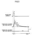
- FIG. 3 shows a detection principle of detecting the concentration. Heating by the heater layer is carried out by supplying heater drive current ih to the heater layer for a predetermined time interval ⁇ t01.
- This ⁇ Tmp12 changes according to the heat transfer characteristic with urea aqueous solution used as medium and this heat transfer characteristic changes according to the concentration of urea .
- concentration Dn can be calculated by converting the calculated ⁇ Tmp12. Further, whether or not the quantity of urea aqueous solution remaining in the storage tank 41 is short can be determined based on the calculated ⁇ Tmp12.
- the first sensor element 7411 is so constructed that the first temperature measuring resistive layer is brought into contact with urea aqueous solution through the fin plate 7414
- a measuring chamber for introducing urea aqueous solution in the storage tank 41 may be formed in the sensor element portion 741 so that the first temperature measuring resistive layer is heated by a heater through urea aqueous solution within this measuring chamber.
- the first temperature measuring resistive layer and urea aqueous solution will come into direct contact with each other.
- the operation of the SCR-C/U 61 is substantially performed as follows. That is, the SCR-C/U 61 carries out detection permission determination ( FIG. 4 : detection permission routine) and only when detection of the concentration is permitted by this determination, the concentration Dn is detected. When the detected Dn is within a predetermined range which is specified as normal area of concentration, it is determined that no specified abnormality concerning urea aqueous solution is generated and an output indicating concentration Dn is delivered.
- detection permission determination FIG. 4 : detection permission routine
- abnormality in remaining amount an abnormality concerning the remaining amount of urea aqueous solution
- an abnormality concerning the concentration of urea aqueous solution is detected when the Dn is in an area below this range.
- the validity of the concentration is determined from viewpoints of the temperature equilibrium of urea aqueous solution within the storage tank 41 ( FIG. 6 : concentration abnormality validity determination routine) and its detection result is treated as a decided result only when it is determined that the result is valid.
- error counters CNTc, CNTe are incremented by each predetermined value each time when each abnormality is detected, and when the error counters CNTc, CNTe reach predetermined values CNTclim, CNTelim, actually, occurrence of abnormality is determined ( FIG. 5 : concentration detection/abnormality determination routine).
- the SCR-C/U 61 delivers an output signal indicating stopping of injection of urea aqueous solution to the injection nozzle 43 ( FIG. 8 : urea aqueous solution injection control routine).
- FIG. 8 urea aqueous solution injection control routine
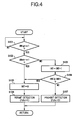
- FIG. 4 is a flow chart of the detection permission routine. This routine is started when the ignition switch is turned ON and after that, it is repeated every predetermined time interval. Detection of the concentration Dn is permitted or prohibited by this routine.
- S101 an ignition switch signal SWign is read, and determination is made as to whether or not SWign is 1. When it is 1, it is determined that the ignition switch is turned ON and the procedure proceeds to S102.
- the start switch signal SWstr is read in, and determination is made as to whether or not the SWstr is 1. When it is 1, it is determined that the start switch is turned ON to start the engine 1. Then, the procedure proceeds to S103, in order to execute permission determination. When it is not 1, the procedure proceeds to S105. In S103, a detection interval INT is reset to 0.
- a permission determination flag Fdtc is set to 1 and permission determination is executed.
- INT1 a predetermined value
- FIG. 5 is a flow chart of concentration detection/abnormality determination routine. This routine is carried out when the permission determination flag Fdtc is set to 1 by the aforementioned detection permission routine. The concentration Dn is detected by this routine and at the same time, a specified abnormality concerning urea aqueous solution is detected.
- the permission determination flag Fdtc is read in, and determination is made as to whether or not the read Fdtc is 1. Only when it is 1, the procedure proceeds to S202.
- electricity is supplied to the heater layer of the urea sensor 74, in order to detect the concentration Dn so that the first temperature measuring resistive layer is heated.
- the concentration Dn is detected. The detection of the concentration Dn is carried out by detecting resistance values Rn1, Rn2 of each heated temperature measuring resistive layer, calculating a temperature difference ⁇ Tmp12 between the temperature measuring resistive layers corresponding to a difference between the detected Rn1 and Rn2 and converting the calculated ⁇ Tmp12 into the concentration Dn.
- S204 determination is made as to whether or not the detected Dn is in a predetermined range (which corresponds to "normal range") in which a first value D1 and a second value D2 which is larger than this first value serve as a lower limit and an upper limit, respectively. When it is within this range, the procedure proceeds to S218, or otherwise the procedure proceeds to S205. In S205, whether or not the concentration Dn is equal to or higher than a predetermined second value D2 is determined. When it is equal to or higher than D2, the procedure proceeds to S214 and when it is lower than D2, the procedure proceeds to S206.
- This D2 is set to an intermediate value between an output Dn obtained when the urea sensor 74 is in urea aqueous solution and an output Dn obtained when the urea sensor 74 is in the air. That is, when the concentration Dn is equal to or higher than D2, it is determined that this Dn is over the normal area and such an abnormality in remaining amount that the remaining amount is short (or the storage tank 41 is empty) is detected. On the other hand, when the concentration Dn is smaller than D2, it is determined that this Dn is lower than the normal area, so that such an abnormality in concentration that other type aqueous solution (in this case, water is included in concept) than urea aqueous solution of a specified concentration is stored in the storage tank 41 is detected.
- validity of detection of abnormality in concentration is determined. This determination is executed according to the concentration abnormality validity determination routine shown in FIG. 6 from the viewpoint of temperature equilibrium of urea aqueous solution as described above.
- the validity determination flag Fjdg is set to 1 and when it is determined that it is not valid, the validity determination flag Fjdg is set to 0.
- a backup error counter BCKc (which corresponds to the "second counter"). Unlike the concentration error counter CNTc, the backup error counter BCKc is incremented by 1 each time when a concentration lower than the normal range is detected regardless of the validity determination flag Fjdg.
- CNTclim for example, 10
- the remaining amount abnormality determination flag Femp is set to 0 and the remaining amount error counter CNTe is reset to 0.
- a predetermined point b (for example, 1) is added to the remaining amount error counter CNTe.
- CNTelim is determined. When the CNTe reaches the CNTelim, the procedure proceeds to S216 and when it does not reach, this routine is returned.
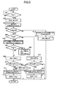
- FIG. 6 is a flow chart indicating a concentration abnormality validity determination routine. This routine is constituted as a sub-routine to be executed in S206 of the aforementioned concentration detection/abnormality determination routine. The validity of detection of abnormality in concentration is determined by this routine.
- a temperature Turea of urea aqueous solution and resistance values Rn1, Rn2 of the temperature measuring resistive layers of the respective sensor elements 7411, 7412 are read in.
- T1 is set to a temperature (-5°C) under which urea is frozen.
- the procedure proceeds to S306 and when it is larger than V1, the procedure proceeds to S309. This is because when VRld is small, the concentration Dn is detected stably and the reliability of a detected Dn is high.
- the DLTt is calculated as a temperature difference DLTt ( FIG. 3 ) between the respective temperature measuring resistive layers which appears just before the heater layer is driven.
- the validity determination flag Fjdg is set to 1 indicating that the detection of abnormality in concentration is valid.
- a predetermined value d is subtracted from the concentration error counter CNTc. In the meantime, this d may be set at each determination of S304 through S307 and values d1 through d4 corresponding to a determination in which a negative result is obtained may be subtracted from the CNTc.
- FIG. 7 is a flow chart indicating a vehicle state determination routine. This routine is repeated every predetermined time interval.
- an engine revolution number NE is read in.
- a vehicle velocity VSP is read in.
- the procedure proceeds to S404 and when it is higher than NE1, the procedure proceeds to S405.
- the read VSP is equal to or less than a predetermined value VSP1 indicating a stopped condition is determined.
- the procedure proceeds to S407 and when it is higher than the VSP1, the procedure proceeds to S405.
- the vehicle state flag Fstb is set to 1.
- the vehicle state flag Fstb is set to 0.
- the concentration Dn is read in.
- determination is made as to whether or not the remaining amount abnormality determination flag Femp is 0.
- the procedure proceeds to S503 and when it is not 0, it is determined that the remaining amount abnormality determination is upheld and the procedure proceeds to S506.
- determination is made as to whether or not the concentration abnormality determination flag Fcon is 0.
- the procedure proceeds to S504 and when it is not 0, it is determined that the concentration abnormality determination is made and the procedure proceeds to S507.
- an injection amount of urea aqueous solution is set.
- Setting of the injection amount of urea aqueous solution is carried out by calculating the basic injection amount corresponding to the fuel injection amount of the engine 1 and an output of the NOx sensor 73, and then correcting the calculated basic injection amount according to the concentration Dn.
- the concentration Dn is large and the urea content per unit injection amount is large, the basic injection amount is reduced by correction.
- the concentration Dn is small and the urea content per unit injection amount is small, the basic injection amount is increased by correction.
- an operation signal corresponding to a set urea aqueous solution injection amount is outputted to the injection nozzle 43.
- the remaining amount alarm lamp 92 provided on the control panel of a driver's seat is operated to make the driver recognize that the remaining amount of urea aqueous solution is short.
- the concentration alarm lamp 91 provided on the control panel is operated for permitting the driver to recognize that other kind of aqueous solution is stored in the storage tank 41.
- injection of urea aqueous solution is stopped. This is because when water or the like is stored in the storage tank 41 instead of urea aqueous solution as well as when the remaining amount of urea aqueous solution is short, an amount of urea aqueous solution necessary for addition of ammonia cannot be injected.
- injection of urea aqueous solution is stopped when each abnormality determination is upheld, it is permissible to output a signal for reducing the emission amount of NOx per se from the engine 1 or controlling the output of the engine 1 to the engine C/U 51 in parallel to or instead of this control.
- the former control the amount of exhaust gas returned through the EGR tube 35 is increased with respect to normal time where other than when abnormality is determined.
- the output characteristic of the engine 1 to accelerator operation is made different from the normal time, for example, fuel injection amount with respect to an accelerator opening degree is reduced as compared to the normal time.
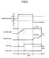
- FIG. 9 is a time chart showing the operation of the SCR-C/U 61, indicating activities of the respective error counters CNTc, CNTe and respective abnormality determination flags Fcnc, Femp when the concentration Dn is shifted from an area A higher than a predetermined range B to an area C lower than this range B (time t3) because water or the like is supplied carelessly or intentionally after the remaining amount abnormality determination (which corresponds to "second abnormality determination") is made (time t2).
- concentration abnormality when concentration abnormality is detected, its validity is determined from the viewpoint of temperature equilibrium according to the flow chart shown in FIG. 6 and detection of concentration abnormality is treated as having been already done only when the validity is determined (time t3 to t4).
- detection of concentration abnormality due to an influence of convection can be avoided preventing such a malfunction as unexpected stopping of injection of urea aqueous solution due to this erroneous detection.
- determination of the validity after the temperature of urea aqueous solution reaches an equilibrium state by heating by the tank heater, it is determined that detection of concentration abnormality is valid because conditions of S303 to S307 of the flow chart shown in FIG. 6 are established as a rule. Further, even before the temperature reaches an equilibrium state, only when these conditions are established, it is determined that detection of concentration abnormality is valid because convection is weak so that a sufficient reliability is compensated for the detection result.
- the error counters CNTc, CNTe which are incremented by each predetermined values a1, a2 and b every time when abnormality in concentration or remaining amount is detected are adopted to secure accuracy of abnormality determination.
- just a frequency may be adopted instead of the error counter.
- the determination of abnormality may be made when a predetermined ratio of concentrations Dn, which is detected over predetermined frequencies, are kept within the area A or C (for example, when the concentrations Dn in that area are detected continuously over predetermined frequencies), after the concentration Dn is moved from an area out of respective areas A, C to that area A, C,
- FIG. 1 does not indicate any catalyst for this hydrolytic degradation clearly. To enhance the efficiency of hydrolytic degradation, it is permissible to arrange the catalyst for hydrolytic degradation at a position upstream of the NOx purifying catalyst 33.
- aqueous solution aqueous solution of a reducing agent such as ammonia water may be adopted as well as urea aqueous solution as aqueous solution of the above adopted precursor.
- the present invention can be applied to a diesel engine other than that of direct fuel-injection type (for example, an auxiliary chamber type diesel engine) and a gasoline engine.
- direct fuel-injection type for example, an auxiliary chamber type diesel engine
- gasoline engine for example, a gasoline engine.
Landscapes
- Engineering & Computer Science (AREA)
- Chemical & Material Sciences (AREA)
- Chemical Kinetics & Catalysis (AREA)
- Environmental & Geological Engineering (AREA)
- Health & Medical Sciences (AREA)
- Combustion & Propulsion (AREA)
- General Chemical & Material Sciences (AREA)
- Oil, Petroleum & Natural Gas (AREA)
- Biomedical Technology (AREA)
- Analytical Chemistry (AREA)
- Mechanical Engineering (AREA)
- General Engineering & Computer Science (AREA)
- Toxicology (AREA)
- Exhaust Gas After Treatment (AREA)
- Exhaust Gas Treatment By Means Of Catalyst (AREA)
- Combined Controls Of Internal Combustion Engines (AREA)
Applications Claiming Priority (2)
| Application Number | Priority Date | Filing Date | Title |
|---|---|---|---|
| JP2005171147A JP4444165B2 (ja) | 2005-06-10 | 2005-06-10 | エンジンの排気浄化装置 |
| PCT/JP2006/311626 WO2006132364A1 (ja) | 2005-06-10 | 2006-06-09 | エンジンの排気浄化装置 |
Publications (3)
| Publication Number | Publication Date |
|---|---|
| EP1908931A1 true EP1908931A1 (de) | 2008-04-09 |
| EP1908931A4 EP1908931A4 (de) | 2010-11-17 |
| EP1908931B1 EP1908931B1 (de) | 2012-05-16 |
Family
ID=37498558
Family Applications (1)
| Application Number | Title | Priority Date | Filing Date |
|---|---|---|---|
| EP06766538A Not-in-force EP1908931B1 (de) | 2005-06-10 | 2006-06-09 | Abgasreinigungsvorrichtung einer brennkraftmaschine |
Country Status (6)
| Country | Link |
|---|---|
| US (1) | US8033096B2 (de) |
| EP (1) | EP1908931B1 (de) |
| JP (1) | JP4444165B2 (de) |
| CN (1) | CN101194087B (de) |
| ES (1) | ES2384984T3 (de) |
| WO (1) | WO2006132364A1 (de) |
Cited By (4)
| Publication number | Priority date | Publication date | Assignee | Title |
|---|---|---|---|---|
| WO2009068881A1 (en) * | 2007-11-30 | 2009-06-04 | Perkins Engines Company Limited | Exhaust treatment system having a diverter valve |
| FR2972489A1 (fr) * | 2011-03-10 | 2012-09-14 | Peugeot Citroen Automobiles Sa | Procede d'estimation de la concentration en reducteur dans une solution de reduction d'oxydes d'azote et systeme scr |
| CN103225533A (zh) * | 2012-01-26 | 2013-07-31 | 福特环球技术公司 | 尿素喷射 |
| WO2014182821A1 (en) * | 2013-05-07 | 2014-11-13 | Tenneco Automotive Operating Company Inc. | Reductant sensor system |
Families Citing this family (26)
| Publication number | Priority date | Publication date | Assignee | Title |
|---|---|---|---|---|
| JP4498983B2 (ja) * | 2005-06-10 | 2010-07-07 | Udトラックス株式会社 | 液体還元剤判別装置 |
| US7665347B2 (en) * | 2005-11-11 | 2010-02-23 | Ngk Spark Plug Co., Ltd. | Liquid state detecting apparatus |
| JP4925890B2 (ja) * | 2007-03-29 | 2012-05-09 | Udトラックス株式会社 | 液体還元剤判別装置及びエンジンの排気浄化装置 |
| JP4895887B2 (ja) * | 2007-03-29 | 2012-03-14 | Udトラックス株式会社 | エンジンの排気浄化装置 |
| JP5118460B2 (ja) * | 2007-12-10 | 2013-01-16 | 三菱ふそうトラック・バス株式会社 | 排気浄化装置 |
| JP4329866B1 (ja) * | 2008-03-07 | 2009-09-09 | トヨタ自動車株式会社 | 車両の制御装置、制御方法およびその方法をコンピュータに実行させるプログラムならびにそのプログラムを記録した記録媒体 |
| JP4692911B2 (ja) * | 2008-09-18 | 2011-06-01 | トヨタ自動車株式会社 | NOxセンサの出力較正装置及び出力較正方法 |
| JP5071341B2 (ja) * | 2008-10-17 | 2012-11-14 | マツダ株式会社 | エンジンの排気浄化装置 |
| DE102008043405B4 (de) * | 2008-11-03 | 2022-02-24 | Robert Bosch Gmbh | Verfahren zur Prüfung der Funktionsfähigkeit einer Pumpe |
| DE102009012092A1 (de) * | 2009-03-06 | 2010-09-09 | Man Nutzfahrzeuge Ag | Verfahren zur Anpassung der Dosiermenge eines Reduktionsmittels zur selektiven katalytischen Reduktion |
| US20110005206A1 (en) * | 2009-07-09 | 2011-01-13 | Li Bob X | Apparatus for Maintaining a Urea Solution in a Liquid State for Treatment of Diesel Exhaust |
| DE102009035940C5 (de) * | 2009-08-03 | 2017-04-20 | Cummins Ltd. | SCR-Abgasnachbehandlungseinrichtung |
| JP5633190B2 (ja) * | 2010-05-25 | 2014-12-03 | いすゞ自動車株式会社 | 復帰制御システム |
| US8978450B2 (en) | 2010-07-22 | 2015-03-17 | Watlow Electric Manufacturing Company | Combination fluid sensor system |
| US8822887B2 (en) | 2010-10-27 | 2014-09-02 | Shaw Arrow Development, LLC | Multi-mode heater for a diesel emission fluid tank |
| US20120102922A1 (en) * | 2010-10-29 | 2012-05-03 | Gm Global Technology Operations, Inc. | Method of sizing a heating core of an exhaust heater for an exhaust treatment system of a vehicle |
| US20130074936A1 (en) * | 2011-09-27 | 2013-03-28 | Caterpillar Inc. | Mis-fill prevention system |
| US8980187B2 (en) | 2011-11-29 | 2015-03-17 | Deere & Company | Diesel particulate filters having a washcoat that improves filter performance |
| CN102518496A (zh) * | 2012-01-05 | 2012-06-27 | 潍柴动力股份有限公司 | 一种尿素喷射量的控制方法和系统 |
| US8890703B2 (en) * | 2013-02-06 | 2014-11-18 | General Electric Company | Passive water heater anode rod depletion sensor algorithm |
| USD729141S1 (en) | 2014-05-28 | 2015-05-12 | Shaw Development LLC | Diesel emissions fluid tank |
| USD729722S1 (en) | 2014-05-28 | 2015-05-19 | Shaw Development LLC | Diesel emissions fluid tank floor |
| SE1550756A1 (en) | 2015-06-09 | 2016-12-10 | Scania Cv Ab | A method and a system for determining a volume of liquid in a container |
| GB2528601A (en) * | 2015-10-16 | 2016-01-27 | Gm Global Tech Operations Inc | A method of managing a selective catalytic reduction system of a motor vehicle |
| CN113175374A (zh) * | 2021-04-30 | 2021-07-27 | 安徽艾可蓝环保股份有限公司 | 一种尿素箱尿素温度和尿素浓度数据处理策略 |
| JP2024100612A (ja) * | 2023-01-16 | 2024-07-26 | 株式会社デンソー | 排気浄化制御装置 |
Family Cites Families (31)
| Publication number | Priority date | Publication date | Assignee | Title |
|---|---|---|---|---|
| JPH04282433A (ja) * | 1991-03-11 | 1992-10-07 | Snow Brand Milk Prod Co Ltd | 液体の濃度測定方法及び装置 |
| JPH05222923A (ja) | 1992-02-06 | 1993-08-31 | Hino Motors Ltd | エンジン排ガスの触媒によるNOx低減装置 |
| JP3468254B2 (ja) | 1995-10-03 | 2003-11-17 | 三菱ふそうトラック・バス株式会社 | ディーゼルエンジンの排気浄化装置 |
| US6063350A (en) | 1997-04-02 | 2000-05-16 | Clean Diesel Technologies, Inc. | Reducing nox emissions from an engine by temperature-controlled urea injection for selective catalytic reduction |
| DE19736384A1 (de) | 1997-08-21 | 1999-02-25 | Man Nutzfahrzeuge Ag | Verfahren zur Dosierung eines Reduktionsmittels in stickoxidhaltiges Abgas einer Brennkraftmaschine |
| DE19756251C1 (de) | 1997-12-17 | 1999-07-22 | Siemens Ag | Verfahren und Vorrichtung zur Reduzierung der Stickoxide im Abgas einer Verbrennungsanlage |
| JP3855444B2 (ja) | 1998-03-24 | 2006-12-13 | トヨタ自動車株式会社 | 内燃機関の還元剤供給装置 |
| DE19818448A1 (de) | 1998-04-24 | 1999-10-28 | Siemens Ag | Verfahren und Vorrichtung zur katalytischen Reduzierung von Stickoxiden im Abgas einer Verbrennungsanlage |
| JP2000027627A (ja) | 1998-07-13 | 2000-01-25 | Hino Motors Ltd | 排気ガス浄化触媒用還元剤保温装置及びそれを組込んだ排気ガス浄化装置 |
| JP2001020724A (ja) | 1999-07-07 | 2001-01-23 | Isuzu Motors Ltd | ディーゼルエンジンのNOx浄化装置 |
| DE19933798C2 (de) | 1999-07-19 | 2001-06-21 | Siemens Ag | Vorrichtung und Verfahren zur Abgasnachbehandlung bei einer Brennkraftmaschine |
| DE10047519A1 (de) | 2000-09-22 | 2002-04-18 | Bosch Gmbh Robert | Verfahren und Vorrichtung zur Dosierung eines Reduktionsmittels zur Entfernung von Stickoxiden aus Abgasen |
| DE10047594A1 (de) | 2000-09-26 | 2002-04-18 | Siemens Ag | Verfahren und Vorrichtung zum Bestimmen des Füllstandes einer Flüssigkeit in einem Behälter |
| JP3600522B2 (ja) | 2000-11-20 | 2004-12-15 | トヨタ自動車株式会社 | 内燃機関の還元剤供給装置 |
| DE10102237A1 (de) * | 2001-01-19 | 2002-08-08 | Bosch Gmbh Robert | Vorrichtung zur Dosierung einer Harnstofflösung |
| JP4270428B2 (ja) | 2001-06-13 | 2009-06-03 | 日産ディーゼル工業株式会社 | 還元剤溶液の自動調合装置 |
| DE10155675A1 (de) | 2001-08-18 | 2003-05-28 | Bosch Gmbh Robert | Verfahren und Vorrichtung zur Speicherung und Dosierung eines Reduktionsmittels |
| JP4243538B2 (ja) | 2001-08-18 | 2009-03-25 | ローベルト ボツシユ ゲゼルシヤフト ミツト ベシユレンクテル ハフツング | 還元剤を貯蔵及び調量する方法並びに装置 |
| JP3956728B2 (ja) | 2002-03-11 | 2007-08-08 | 三菱ふそうトラック・バス株式会社 | 内燃機関のNOx浄化装置 |
| WO2003100225A1 (en) | 2002-05-07 | 2003-12-04 | Extengine Transport Systems | Emission control system |
| JP3861746B2 (ja) | 2002-05-17 | 2006-12-20 | トヨタ自動車株式会社 | 内燃機関の排気浄化装置 |
| WO2004025286A1 (ja) * | 2002-09-10 | 2004-03-25 | Mitsui Mining & Smelting Co., Ltd. | 尿素濃度識別装置および尿素濃度識別方法ならびにそれを用いた自動車の排気ガスの低減装置および自動車の排気ガスの低減方法 |
| JP4199531B2 (ja) | 2002-12-12 | 2008-12-17 | Necエンジニアリング株式会社 | パルスマスク波形整形支援装置 |
| CN100465632C (zh) * | 2003-06-16 | 2009-03-04 | 西门子Vdo汽车公司 | 用于确定液体中的成分的浓度的方法和设备 |
| JP2005030888A (ja) | 2003-07-11 | 2005-02-03 | Mitsui Mining & Smelting Co Ltd | 流量・液種検知装置および流量・液種検知方法 |
| JP3751962B2 (ja) * | 2003-09-05 | 2006-03-08 | 日産ディーゼル工業株式会社 | エンジンの排気浄化装置 |
| JP3687915B2 (ja) * | 2003-10-27 | 2005-08-24 | 日産ディーゼル工業株式会社 | 液体判別装置 |
| JP3687916B2 (ja) | 2003-10-28 | 2005-08-24 | 日産ディーゼル工業株式会社 | エンジンの排気浄化装置 |
| JP3687917B2 (ja) | 2003-10-31 | 2005-08-24 | 日産ディーゼル工業株式会社 | 液体還元剤の濃度及び残量検出装置 |
| JP2005171147A (ja) | 2003-12-12 | 2005-06-30 | Asahi Glass Co Ltd | 物品の洗浄乾燥方法 |
| JP4375248B2 (ja) | 2005-02-17 | 2009-12-02 | 株式会社デンソー | 走行支援装置 |
-
2005
- 2005-06-10 JP JP2005171147A patent/JP4444165B2/ja not_active Expired - Lifetime
-
2006
- 2006-06-09 CN CN2006800205043A patent/CN101194087B/zh not_active Expired - Fee Related
- 2006-06-09 ES ES06766538T patent/ES2384984T3/es active Active
- 2006-06-09 EP EP06766538A patent/EP1908931B1/de not_active Not-in-force
- 2006-06-09 WO PCT/JP2006/311626 patent/WO2006132364A1/ja not_active Ceased
-
2007
- 2007-12-07 US US11/952,397 patent/US8033096B2/en not_active Expired - Fee Related
Cited By (7)
| Publication number | Priority date | Publication date | Assignee | Title |
|---|---|---|---|---|
| WO2009068881A1 (en) * | 2007-11-30 | 2009-06-04 | Perkins Engines Company Limited | Exhaust treatment system having a diverter valve |
| FR2972489A1 (fr) * | 2011-03-10 | 2012-09-14 | Peugeot Citroen Automobiles Sa | Procede d'estimation de la concentration en reducteur dans une solution de reduction d'oxydes d'azote et systeme scr |
| CN103225533A (zh) * | 2012-01-26 | 2013-07-31 | 福特环球技术公司 | 尿素喷射 |
| WO2014182821A1 (en) * | 2013-05-07 | 2014-11-13 | Tenneco Automotive Operating Company Inc. | Reductant sensor system |
| US9752486B2 (en) | 2013-05-07 | 2017-09-05 | Tenneco Automotive Operating Company Inc. | Reductant sensor system |
| US9903250B2 (en) | 2013-05-07 | 2018-02-27 | Tenneco Automotive Operating Company Inc. | Recirculating exhaust treatment fluid system |
| US10082067B2 (en) | 2013-05-07 | 2018-09-25 | Tenneco Automotive Operating Company Inc. | Recirculating exhaust treatment fluid system |
Also Published As
| Publication number | Publication date |
|---|---|
| ES2384984T3 (es) | 2012-07-16 |
| JP2006342771A (ja) | 2006-12-21 |
| CN101194087A (zh) | 2008-06-04 |
| EP1908931A4 (de) | 2010-11-17 |
| CN101194087B (zh) | 2010-05-19 |
| EP1908931B1 (de) | 2012-05-16 |
| JP4444165B2 (ja) | 2010-03-31 |
| US20080087009A1 (en) | 2008-04-17 |
| WO2006132364A1 (ja) | 2006-12-14 |
| US8033096B2 (en) | 2011-10-11 |
Similar Documents
| Publication | Publication Date | Title |
|---|---|---|
| EP1908931B1 (de) | Abgasreinigungsvorrichtung einer brennkraftmaschine | |
| EP1830040B1 (de) | Motorabgasreinigungsvorrichtung | |
| JP3687916B2 (ja) | エンジンの排気浄化装置 | |
| EP1688599B1 (de) | Motorsteuerung und motorbetriebsverfahren | |
| JP5533235B2 (ja) | NOxセンサ診断装置及びSCRシステム | |
| CN102037230A (zh) | NOx传感器的异常诊断装置及异常诊断方法 | |
| JP2010261326A (ja) | 還元剤の異常検出方法 | |
| US20040083721A1 (en) | Diesel aftertreatment systems | |
| CN100416054C (zh) | 发动机控制装置和发动机运转方法 | |
| JP4884270B2 (ja) | エンジンの排気浄化装置 | |
| EP2896799B1 (de) | Additivzugabevorrichtung | |
| EP3048276A1 (de) | Diagnosevorrichtung | |
| JP4419150B2 (ja) | NOx触媒の異常診断装置及び異常診断方法 | |
| JP2013194723A (ja) | 内燃機関の排ガス浄化装置 |
Legal Events
| Date | Code | Title | Description |
|---|---|---|---|
| PUAI | Public reference made under article 153(3) epc to a published international application that has entered the european phase |
Free format text: ORIGINAL CODE: 0009012 |
|
| 17P | Request for examination filed |
Effective date: 20080108 |
|
| AK | Designated contracting states |
Kind code of ref document: A1 Designated state(s): AT BE BG CH CY CZ DE DK EE ES FI FR GB GR HU IE IS IT LI LT LU LV MC NL PL PT RO SE SI SK TR |
|
| DAX | Request for extension of the european patent (deleted) | ||
| A4 | Supplementary search report drawn up and despatched |
Effective date: 20101014 |
|
| REG | Reference to a national code |
Ref country code: DE Ref legal event code: R079 Ref document number: 602006029522 Country of ref document: DE Free format text: PREVIOUS MAIN CLASS: F01N0003080000 Ipc: F01N0003200000 |
|
| GRAP | Despatch of communication of intention to grant a patent |
Free format text: ORIGINAL CODE: EPIDOSNIGR1 |
|
| RIC1 | Information provided on ipc code assigned before grant |
Ipc: B01D 53/94 20060101ALI20111130BHEP Ipc: F01N 3/20 20060101AFI20111130BHEP Ipc: B01D 53/90 20060101ALI20111130BHEP |
|
| GRAS | Grant fee paid |
Free format text: ORIGINAL CODE: EPIDOSNIGR3 |
|
| GRAA | (expected) grant |
Free format text: ORIGINAL CODE: 0009210 |
|
| AK | Designated contracting states |
Kind code of ref document: B1 Designated state(s): AT BE BG CH CY CZ DE DK EE ES FI FR GB GR HU IE IS IT LI LT LU LV MC NL PL PT RO SE SI SK TR |
|
| REG | Reference to a national code |
Ref country code: GB Ref legal event code: FG4D |
|
| REG | Reference to a national code |
Ref country code: CH Ref legal event code: EP |
|
| REG | Reference to a national code |
Ref country code: AT Ref legal event code: REF Ref document number: 558208 Country of ref document: AT Kind code of ref document: T Effective date: 20120615 |
|
| REG | Reference to a national code |
Ref country code: IE Ref legal event code: FG4D |
|
| REG | Reference to a national code |
Ref country code: ES Ref legal event code: FG2A Ref document number: 2384984 Country of ref document: ES Kind code of ref document: T3 Effective date: 20120716 |
|
| REG | Reference to a national code |
Ref country code: DE Ref legal event code: R096 Ref document number: 602006029522 Country of ref document: DE Effective date: 20120719 |
|
| REG | Reference to a national code |
Ref country code: SE Ref legal event code: TRGR |
|
| REG | Reference to a national code |
Ref country code: NL Ref legal event code: T3 |
|
| REG | Reference to a national code |
Ref country code: LT Ref legal event code: MG4D Effective date: 20120516 |
|
| PG25 | Lapsed in a contracting state [announced via postgrant information from national office to epo] |
Ref country code: FI Free format text: LAPSE BECAUSE OF FAILURE TO SUBMIT A TRANSLATION OF THE DESCRIPTION OR TO PAY THE FEE WITHIN THE PRESCRIBED TIME-LIMIT Effective date: 20120516 Ref country code: LT Free format text: LAPSE BECAUSE OF FAILURE TO SUBMIT A TRANSLATION OF THE DESCRIPTION OR TO PAY THE FEE WITHIN THE PRESCRIBED TIME-LIMIT Effective date: 20120516 Ref country code: CY Free format text: LAPSE BECAUSE OF FAILURE TO SUBMIT A TRANSLATION OF THE DESCRIPTION OR TO PAY THE FEE WITHIN THE PRESCRIBED TIME-LIMIT Effective date: 20120516 Ref country code: PL Free format text: LAPSE BECAUSE OF FAILURE TO SUBMIT A TRANSLATION OF THE DESCRIPTION OR TO PAY THE FEE WITHIN THE PRESCRIBED TIME-LIMIT Effective date: 20120516 Ref country code: IS Free format text: LAPSE BECAUSE OF FAILURE TO SUBMIT A TRANSLATION OF THE DESCRIPTION OR TO PAY THE FEE WITHIN THE PRESCRIBED TIME-LIMIT Effective date: 20120916 |
|
| REG | Reference to a national code |
Ref country code: AT Ref legal event code: MK05 Ref document number: 558208 Country of ref document: AT Kind code of ref document: T Effective date: 20120516 |
|
| PG25 | Lapsed in a contracting state [announced via postgrant information from national office to epo] |
Ref country code: SI Free format text: LAPSE BECAUSE OF FAILURE TO SUBMIT A TRANSLATION OF THE DESCRIPTION OR TO PAY THE FEE WITHIN THE PRESCRIBED TIME-LIMIT Effective date: 20120516 Ref country code: PT Free format text: LAPSE BECAUSE OF FAILURE TO SUBMIT A TRANSLATION OF THE DESCRIPTION OR TO PAY THE FEE WITHIN THE PRESCRIBED TIME-LIMIT Effective date: 20120917 Ref country code: GR Free format text: LAPSE BECAUSE OF FAILURE TO SUBMIT A TRANSLATION OF THE DESCRIPTION OR TO PAY THE FEE WITHIN THE PRESCRIBED TIME-LIMIT Effective date: 20120817 Ref country code: LV Free format text: LAPSE BECAUSE OF FAILURE TO SUBMIT A TRANSLATION OF THE DESCRIPTION OR TO PAY THE FEE WITHIN THE PRESCRIBED TIME-LIMIT Effective date: 20120516 |
|
| PG25 | Lapsed in a contracting state [announced via postgrant information from national office to epo] |
Ref country code: RO Free format text: LAPSE BECAUSE OF FAILURE TO SUBMIT A TRANSLATION OF THE DESCRIPTION OR TO PAY THE FEE WITHIN THE PRESCRIBED TIME-LIMIT Effective date: 20120516 Ref country code: SK Free format text: LAPSE BECAUSE OF FAILURE TO SUBMIT A TRANSLATION OF THE DESCRIPTION OR TO PAY THE FEE WITHIN THE PRESCRIBED TIME-LIMIT Effective date: 20120516 Ref country code: DK Free format text: LAPSE BECAUSE OF FAILURE TO SUBMIT A TRANSLATION OF THE DESCRIPTION OR TO PAY THE FEE WITHIN THE PRESCRIBED TIME-LIMIT Effective date: 20120516 Ref country code: EE Free format text: LAPSE BECAUSE OF FAILURE TO SUBMIT A TRANSLATION OF THE DESCRIPTION OR TO PAY THE FEE WITHIN THE PRESCRIBED TIME-LIMIT Effective date: 20120516 Ref country code: CZ Free format text: LAPSE BECAUSE OF FAILURE TO SUBMIT A TRANSLATION OF THE DESCRIPTION OR TO PAY THE FEE WITHIN THE PRESCRIBED TIME-LIMIT Effective date: 20120516 Ref country code: AT Free format text: LAPSE BECAUSE OF FAILURE TO SUBMIT A TRANSLATION OF THE DESCRIPTION OR TO PAY THE FEE WITHIN THE PRESCRIBED TIME-LIMIT Effective date: 20120516 Ref country code: MC Free format text: LAPSE BECAUSE OF NON-PAYMENT OF DUE FEES Effective date: 20120630 |
|
| REG | Reference to a national code |
Ref country code: CH Ref legal event code: PL |
|
| REG | Reference to a national code |
Ref country code: CH Ref legal event code: PL |
|
| PLBE | No opposition filed within time limit |
Free format text: ORIGINAL CODE: 0009261 |
|
| STAA | Information on the status of an ep patent application or granted ep patent |
Free format text: STATUS: NO OPPOSITION FILED WITHIN TIME LIMIT |
|
| REG | Reference to a national code |
Ref country code: IE Ref legal event code: MM4A |
|
| 26N | No opposition filed |
Effective date: 20130219 |
|
| GBPC | Gb: european patent ceased through non-payment of renewal fee |
Effective date: 20120816 |
|
| PG25 | Lapsed in a contracting state [announced via postgrant information from national office to epo] |
Ref country code: LI Free format text: LAPSE BECAUSE OF NON-PAYMENT OF DUE FEES Effective date: 20120630 Ref country code: IE Free format text: LAPSE BECAUSE OF NON-PAYMENT OF DUE FEES Effective date: 20120609 Ref country code: CH Free format text: LAPSE BECAUSE OF NON-PAYMENT OF DUE FEES Effective date: 20120630 |
|
| REG | Reference to a national code |
Ref country code: DE Ref legal event code: R097 Ref document number: 602006029522 Country of ref document: DE Effective date: 20130219 |
|
| PG25 | Lapsed in a contracting state [announced via postgrant information from national office to epo] |
Ref country code: GB Free format text: LAPSE BECAUSE OF NON-PAYMENT OF DUE FEES Effective date: 20120816 Ref country code: BG Free format text: LAPSE BECAUSE OF FAILURE TO SUBMIT A TRANSLATION OF THE DESCRIPTION OR TO PAY THE FEE WITHIN THE PRESCRIBED TIME-LIMIT Effective date: 20120816 |
|
| PG25 | Lapsed in a contracting state [announced via postgrant information from national office to epo] |
Ref country code: TR Free format text: LAPSE BECAUSE OF FAILURE TO SUBMIT A TRANSLATION OF THE DESCRIPTION OR TO PAY THE FEE WITHIN THE PRESCRIBED TIME-LIMIT Effective date: 20120516 |
|
| PG25 | Lapsed in a contracting state [announced via postgrant information from national office to epo] |
Ref country code: LU Free format text: LAPSE BECAUSE OF NON-PAYMENT OF DUE FEES Effective date: 20120609 |
|
| PG25 | Lapsed in a contracting state [announced via postgrant information from national office to epo] |
Ref country code: HU Free format text: LAPSE BECAUSE OF FAILURE TO SUBMIT A TRANSLATION OF THE DESCRIPTION OR TO PAY THE FEE WITHIN THE PRESCRIBED TIME-LIMIT Effective date: 20060609 |
|
| REG | Reference to a national code |
Ref country code: FR Ref legal event code: PLFP Year of fee payment: 11 |
|
| REG | Reference to a national code |
Ref country code: FR Ref legal event code: PLFP Year of fee payment: 12 |
|
| REG | Reference to a national code |
Ref country code: FR Ref legal event code: PLFP Year of fee payment: 13 |
|
| REG | Reference to a national code |
Ref country code: DE Ref legal event code: R081 Ref document number: 602006029522 Country of ref document: DE Owner name: VOLVO TRUCK CORPORATION, SE Free format text: FORMER OWNER: NISSAN DIESEL MOTOR CO., LTD., AGEO, SAITAMA, JP |
|
| REG | Reference to a national code |
Ref country code: BE Ref legal event code: PD Owner name: UD TRUCKS CORPORATION; JP Free format text: DETAILS ASSIGNMENT: CHANGE OF OWNER(S), ASSIGNMENT; FORMER OWNER NAME: NISSAN DIESEL MOTOR CO., LTD. Effective date: 20211018 Ref country code: BE Ref legal event code: PD Owner name: UD TRUCKS CORPORATION; JP Free format text: DETAILS ASSIGNMENT: CHANGE OF OWNER(S), ASSIGNMENT; FORMER OWNER NAME: UD TRUCKS CORPORATION Effective date: 20211018 Ref country code: BE Ref legal event code: HC Owner name: VOLVO TRUCK CORPORATION; SE Free format text: DETAILS ASSIGNMENT: CHANGE OF OWNER(S), CHANGE OF OWNER(S) NAME; FORMER OWNER NAME: VOLVO GROUP SWEDEN AB Effective date: 20211018 |
|
| REG | Reference to a national code |
Ref country code: NL Ref legal event code: PD Owner name: VOLVO TRUCK CORPORATION; SE Free format text: DETAILS ASSIGNMENT: CHANGE OF OWNER(S), ASSIGNMENT; FORMER OWNER NAME: VOLVO GROUP SWEDEN AB Effective date: 20211125 |
|
| REG | Reference to a national code |
Ref country code: ES Ref legal event code: PC2A Owner name: VOLVO TRUCK CORPORATION Effective date: 20220310 |
|
| PGFP | Annual fee paid to national office [announced via postgrant information from national office to epo] |
Ref country code: SE Payment date: 20220622 Year of fee payment: 17 Ref country code: NL Payment date: 20220627 Year of fee payment: 17 Ref country code: IT Payment date: 20220622 Year of fee payment: 17 |
|
| PGFP | Annual fee paid to national office [announced via postgrant information from national office to epo] |
Ref country code: BE Payment date: 20220627 Year of fee payment: 17 |
|
| PGFP | Annual fee paid to national office [announced via postgrant information from national office to epo] |
Ref country code: FR Payment date: 20220623 Year of fee payment: 17 |
|
| PGFP | Annual fee paid to national office [announced via postgrant information from national office to epo] |
Ref country code: ES Payment date: 20220714 Year of fee payment: 17 Ref country code: DE Payment date: 20220628 Year of fee payment: 17 |
|
| REG | Reference to a national code |
Ref country code: DE Ref legal event code: R119 Ref document number: 602006029522 Country of ref document: DE |
|
| REG | Reference to a national code |
Ref country code: SE Ref legal event code: EUG |
|
| REG | Reference to a national code |
Ref country code: NL Ref legal event code: MM Effective date: 20230701 |
|
| REG | Reference to a national code |
Ref country code: BE Ref legal event code: MM Effective date: 20230630 |
|
| PG25 | Lapsed in a contracting state [announced via postgrant information from national office to epo] |
Ref country code: NL Free format text: LAPSE BECAUSE OF NON-PAYMENT OF DUE FEES Effective date: 20230701 |
|
| PG25 | Lapsed in a contracting state [announced via postgrant information from national office to epo] |
Ref country code: DE Free format text: LAPSE BECAUSE OF NON-PAYMENT OF DUE FEES Effective date: 20240103 |
|
| PG25 | Lapsed in a contracting state [announced via postgrant information from national office to epo] |
Ref country code: SE Free format text: LAPSE BECAUSE OF NON-PAYMENT OF DUE FEES Effective date: 20230610 Ref country code: FR Free format text: LAPSE BECAUSE OF NON-PAYMENT OF DUE FEES Effective date: 20230630 Ref country code: BE Free format text: LAPSE BECAUSE OF NON-PAYMENT OF DUE FEES Effective date: 20230630 |
|
| REG | Reference to a national code |
Ref country code: ES Ref legal event code: FD2A Effective date: 20240729 |
|
| PG25 | Lapsed in a contracting state [announced via postgrant information from national office to epo] |
Ref country code: IT Free format text: LAPSE BECAUSE OF NON-PAYMENT OF DUE FEES Effective date: 20230609 |
|
| PG25 | Lapsed in a contracting state [announced via postgrant information from national office to epo] |
Ref country code: ES Free format text: LAPSE BECAUSE OF NON-PAYMENT OF DUE FEES Effective date: 20230610 |
|
| PG25 | Lapsed in a contracting state [announced via postgrant information from national office to epo] |
Ref country code: ES Free format text: LAPSE BECAUSE OF NON-PAYMENT OF DUE FEES Effective date: 20230610 |