EP1908938A2 - Gasturbinenwellenmontage - Google Patents
Gasturbinenwellenmontage Download PDFInfo
- Publication number
- EP1908938A2 EP1908938A2 EP07116221A EP07116221A EP1908938A2 EP 1908938 A2 EP1908938 A2 EP 1908938A2 EP 07116221 A EP07116221 A EP 07116221A EP 07116221 A EP07116221 A EP 07116221A EP 1908938 A2 EP1908938 A2 EP 1908938A2
- Authority
- EP
- European Patent Office
- Prior art keywords
- gas turbine
- turbine engine
- shaft
- pressure turbine
- assembly
- Prior art date
- Legal status (The legal status is an assumption and is not a legal conclusion. Google has not performed a legal analysis and makes no representation as to the accuracy of the status listed.)
- Withdrawn
Links
- 238000011144 upstream manufacturing Methods 0.000 claims abstract description 5
- 230000001419 dependent effect Effects 0.000 claims 4
- 230000008878 coupling Effects 0.000 description 4
- 238000010168 coupling process Methods 0.000 description 4
- 238000005859 coupling reaction Methods 0.000 description 4
- 238000000034 method Methods 0.000 description 4
- 230000003247 decreasing effect Effects 0.000 description 2
- 238000005096 rolling process Methods 0.000 description 2
- 238000000429 assembly Methods 0.000 description 1
- 230000000712 assembly Effects 0.000 description 1
- 238000005452 bending Methods 0.000 description 1
- 238000005219 brazing Methods 0.000 description 1
- 238000002485 combustion reaction Methods 0.000 description 1
- 230000008030 elimination Effects 0.000 description 1
- 238000003379 elimination reaction Methods 0.000 description 1
- 239000000446 fuel Substances 0.000 description 1
- 238000012423 maintenance Methods 0.000 description 1
- 238000012986 modification Methods 0.000 description 1
- 230000004048 modification Effects 0.000 description 1
- 238000004513 sizing Methods 0.000 description 1
- 230000007704 transition Effects 0.000 description 1
- 238000003466 welding Methods 0.000 description 1
Images


Classifications
-
- F—MECHANICAL ENGINEERING; LIGHTING; HEATING; WEAPONS; BLASTING
- F02—COMBUSTION ENGINES; HOT-GAS OR COMBUSTION-PRODUCT ENGINE PLANTS
- F02C—GAS-TURBINE PLANTS; AIR INTAKES FOR JET-PROPULSION PLANTS; CONTROLLING FUEL SUPPLY IN AIR-BREATHING JET-PROPULSION PLANTS
- F02C7/00—Features, components parts, details or accessories, not provided for in, or of interest apart form groups F02C1/00 - F02C6/00; Air intakes for jet-propulsion plants
- F02C7/36—Power transmission arrangements between the different shafts of the gas turbine plant, or between the gas-turbine plant and the power user
-
- F—MECHANICAL ENGINEERING; LIGHTING; HEATING; WEAPONS; BLASTING
- F01—MACHINES OR ENGINES IN GENERAL; ENGINE PLANTS IN GENERAL; STEAM ENGINES
- F01D—NON-POSITIVE DISPLACEMENT MACHINES OR ENGINES, e.g. STEAM TURBINES
- F01D25/00—Component parts, details, or accessories, not provided for in, or of interest apart from, other groups
- F01D25/16—Arrangement of bearings; Supporting or mounting bearings in casings
- F01D25/162—Bearing supports
-
- F—MECHANICAL ENGINEERING; LIGHTING; HEATING; WEAPONS; BLASTING
- F01—MACHINES OR ENGINES IN GENERAL; ENGINE PLANTS IN GENERAL; STEAM ENGINES
- F01D—NON-POSITIVE DISPLACEMENT MACHINES OR ENGINES, e.g. STEAM TURBINES
- F01D5/00—Blades; Blade-carrying members; Heating, heat-insulating, cooling or antivibration means on the blades or the members
- F01D5/02—Blade-carrying members, e.g. rotors
- F01D5/06—Rotors for more than one axial stage, e.g. of drum or multiple disc type; Details thereof, e.g. shafts, shaft connections
- F01D5/066—Connecting means for joining rotor-discs or rotor-elements together, e.g. by a central bolt, by clamps
Definitions
- This invention relates generally to gas turbine engines, and more specifically to gas turbine engine assemblies and methods of assembling the same.
- At least some known gas turbine engines include a fan, a core gas turbine engine, and a power or low-pressure turbine.
- the core engine includes a high-pressure compressor, a combustor, and a high-pressure turbine that are coupled together in a serial flow relationship.
- the low-pressure turbine is coupled downstream from, and driven by, the core gas turbine engine. More specifically, the high-pressure compressor and the high-pressure turbine are coupled together using a first shaft to define a high-pressure rotor assembly, and the low-pressure turbine and the fan are coupled together using a second shaft. Air entering the core engine is mixed with fuel and ignited to form a high energy gas stream. The high energy gas stream is discharged through the high-pressure turbine to drive the high-pressure turbine and thus also drive the low-pressure turbine.
- gas turbine engines under design consideration include a high-pressure turbine disk that has a bore diameter that is substantially smaller than the bore diameter of known high-pressure turbine disks. Utilizing a high-pressure turbine disk having a relatively small bore diameter may result in an increase of the disk life by reducing disk stress.
- the core gas turbine engine is sized to accommodate the high-pressure turbine disk. While sizing the high-pressure turbine disk may increase the life of the disk, the core gas turbine engine must still be designed to have an acceptable speed margin between operating speed and the first critical.
- a method of assembling a gas turbine engine assembly includes coupling a fan assembly to a core gas turbine engine such that the fan assembly is upstream from the core gas turbine engine, coupling a low-pressure turbine downstream from the core gas turbine engine such, wherein the low-pressure turbine includes a disk having a flange and a plurality of splines formed in the flange, providing a shaft that includes a first end and a second end that includes a plurality of splines, coupling the shaft first end to the fan assembly, coupling the shaft second end to the low-pressure turbine such that the shaft splines mesh with the flange splines such that torque is transmitted from the low-pressure turbine to the fan assembly via the shaft during engine operation.
- a gas turbine engine assembly in another aspect, includes a core gas turbine engine including a high-pressure turbine, a fan assembly coupled to the core gas turbine engine such that the fan assembly is upstream from the core gas turbine engine, a low-pressure turbine coupled to the core gas turbine engine, the low-pressure turbine coupled downstream from the core gas turbine engine, the low-pressure turbine comprising a disk including a flange a plurality of splines formed in the flange, and a shaft comprising a first end coupled to the fan assembly and a second end that comprises a plurality of splines, and a differential bearing coupled between the shaft and the high-pressure turbine, the differential bearing configured to provide rotational support for the high-pressure turbine.
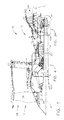
- FIG. 1 is a schematic illustration of an exemplary gas turbine engine assembly 10 having a longitudinal axis 11.
- Gas turbine engine assembly 10 includes a fan assembly 12 and a core gas turbine engine 13.
- Core gas turbine engine 13 includes a high pressure compressor 14, a combustor 16, and a high pressure turbine 18.
- Gas turbine engine assembly 10 also includes a low pressure turbine 20 and a multi-stage booster compressor 22.
- Fan assembly 12 includes an array of fan blades 24 extending radially outward from a rotor disk 26.
- Gas turbine engine assembly 10 has an intake side 28 and an exhaust side 30.
- Fan assembly 12, booster 22, and low-pressure turbine 20 are coupled together by a first rotor shaft 31, and compressor 14 and turbine 18 are coupled together by a second rotor shaft 32.
- the compressed air that is discharged from booster 22 is channeled through compressor 14 wherein the airflow is further compressed and delivered to combustor 16.
- Hot products of combustion (not shown in Figure 1) from combustor 16 are utilized to drive turbines 18 and 20, and turbine 20 is utilized to drive fan assembly 12 and booster 22 by way of shaft 31.
- Gas turbine engine assembly 10 is operable at a range of operating conditions between design operating conditions and off-design operating conditions.
- FIG. 2 is a cross-sectional view of a shaft 31 shown in Figure 1.
- shaft 31 includes a first portion 100, a second portion 102 and a transition portion 104 that is coupled between first and second portions 100 and 102.
- low-pressure turbine 20 includes a rotor disk 105, a flange formed 107 formed with rotor disk 105, a bore 106 that extends through flange 107, and a plurality of splines 108 that are formed around the radially inner surface of flange 107.
- bore 106 is formed through a centerline of flange 107 around longitudinal axis 11.
- shaft 31 includes a plurality of splines 110 that are configured to mesh with a flange splines 108 such that torque is transmitted from low-pressure turbine 20 to fan assembly 12 via shaft 31 during engine operation.
- Shaft 31 also includes a first end 120 that is coupled to fan assembly 12 and a second end 122 that includes shaft splines 110 that is coupled to low-pressure turbine 20.
- flange splines 108 are female splines and shaft splines 110 are male splines configured to mesh with the female splines.
- shaft splines 110 are female splines and flange splines 108 are male splines.
- splines are denote a series of ridges that are formed on a shaft or through a disk that mesh with and equalize the rotational speed of the pieces splined together, thereby transferring torque.
- shaft 31 is configured to accommodate an oversized high-pressure turbine 18. More specifically, since high-pressure turbine 18 has an inner diameter 130 that is substantially smaller than known high-pressure turbines, shaft 31 is selectively sized to accommodate the substantially larger high-pressure turbine. As such, shaft first end 120 has an outer diameter 132 that is greater than the inner diameter 130 of high-pressure turbine disk 18, and shaft second end 122 has an outer diameter 134 that is less than outer diameter 132. This configuration enables shaft second end 122 to be installed through a bore 136 formed through high-pressure turbine 18 and coupled to low-pressure turbine 20.
- first portion diameter 132 is substantially greater than second portion diameter 134.
- first portion 100 has a diameter 132 that is approximately 4.5 inches
- second portion 102 has a diameter 134 that is approximately 3.5 inches.
- second diameter 134 is selected based on the inner diameter 130 of high-pressure turbine 18, and as such, may be either increased or decreased to ensure that shaft 31 is capable of being inserted through high-pressure turbine bore 136 and coupled to low-pressure turbine 20.
- first portion 100 has a length 140 that is greater than a length 142 of second portion 102.
- the thickness or diameter 132 of first shaft portion 100 along length 140 is substantially larger than diameter 134 of second shaft portion 102 along length 142.
- the length 140 of first portion 100 is selected such that the diameter 132 of first portion 100 can be maximized between the fan assembly 12 and the high-pressure turbine 18, wherein the diameter of shaft 31 is reduced to allow shaft 31 to extend through disk bore 136 and be coupled to low-pressure turbine 20.
- the length 140 of first portion 100 is substantially greater than the length 142 of second portion 102.
- shaft 31 includes first, second, and third portions 100, 102, and 104, respectively.
- first, second, and third portions 100, 102, and 104 are fabricated as separate components that are coupled together using a welding or brazing procedure, for example.
- first, second, and third portions are formed as single unitary shaft 31.
- Figure 3 is an enlarged cross-sectional view of a downstream portion of the gas turbine engine assembly shown in Figure 1.
- Figure 4 is an enlarged cross-sectional view of a forward portion of the gas turbine engine assembly shown in Figure 1.
- the low-pressure turbine 20 is coupled to a downstream end of core gas turbine engine 13.
- Shaft 31 is then inserted through core gas turbine engine 13, including high-pressure turbine 18 such that shaft second end 122 is inserted at least partially into low-pressure turbine 20 and such that flange splines 108 mesh with shaft splines 110.
- gas turbine engine assembly 10 also includes a differential bearing assembly 170 that is positioned between the low-pressure turbine 20 and the high-pressure turbine 18 such that the low-pressure turbine shaft 31 supports the high-pressure turbine 18.
- gas turbine engine assembly 10 includes a cone shaft 172 that is utilized to couple high-pressure turbine 18 to bearing assembly 170, and thus to low-pressure turbine shaft 31.
- Differential bearing assembly 170 includes a rotating inner race 180 that is secured to shaft 31, a rotating outer race 182 that is secured to cone shaft 172, and a plurality of rolling elements 184 that are positioned between inner and outer races 180 and 182, respectively.
- bearing assembly 170 includes a plurality of roller bearings 184 that provide rotational support for high-pressure turbine 18 and thus eliminate the frame assembly and bearings that are typically used to support the high-pressure turbine.
- gas turbine engine assembly 10 includes a bearing assembly 190 that is coupled between shaft 31 and a turbine rear frame 192. Bearing assembly 190 is configured to support the aft end of shaft 31 and thus also provide support for the high-pressure turbine 18.
- bearing assembly 150 includes a rotating inner race 152 that is secured to shaft 31, a stationary outer race 154 that is coupled to a frame 160, and a plurality of rolling elements 156 that are positioned between inner and outer races 152 and 154, respectively.
- bearing assembly 150 is a roller bearing assembly that provides rotational support for shaft 31 and facilitates reducing shaft flexing.
- Fan assembly 12 is then coupled to an upstream end of core gas turbine engine 13, and shaft first end 120 is coupled to fan assembly 12 such that low-pressure turbine 20 is then coupled to fan assembly 12.
- a gas turbine engine assembly that includes a fan assembly, a core gas turbine engine, a low-pressure turbine, and a shaft coupled between the fan assembly and the low-pressure turbine.
- the gas turbine engine described herein includes a low-pressure turbine shaft that enables a high-pressure turbine having a smaller flange bore diameter to be utilized. As a result, the life span of the high-pressure turbine is increased by reducing stress, while still maintaining an acceptable speed margin between operating speed and the first critical.
- the diameter of the high-pressure turbine flange is decreased by utilizing a low-pressure turbine shaft that is splined to the low-pressure turbine flange at the aft end of the gas turbine engine assembly, whereas known gas turbines includes splines at the forward end of the low-pressure turbine shaft.
- a reduced shaft diameter occurs at the end of the shaft which allows the high-pressure turbine disk to be designed with a smaller bore radius and therefore increase the life of the high-pressure turbine.
- the gas turbine engine described herein also includes a differential bearing that is coupled between the low-pressure turbine shaft and the high-pressure turbine at the aft end of the gas turbine engine.
- the differential bearing is configured to support the high-pressure turbine and thus eliminate the need for a turbine midframe which is typically used to support the high-pressure turbine. This configuration reduces the complexity of engine assembly and disassembly. For example, since the low-pressure turbine shaft is splined at the aft end, the shaft may be installed and removed from the front of the gas turbine engine, thus improving assembly and disassembly of the gas turbine engine.
- the reduced complexity of assembly and disassembly may allow for the elimination of the lower low-pressure turbine torque cone flange thus reducing cost and weight, which are replaced by circumferential bosses which provide a bolting surface for the seals. Weight savings will also occur by incorporating smaller bolts used to hold the seals since the flange required for transmitting full low-pressure shaft torque has been eliminated.
Landscapes
- Engineering & Computer Science (AREA)
- Mechanical Engineering (AREA)
- General Engineering & Computer Science (AREA)
- Chemical & Material Sciences (AREA)
- Combustion & Propulsion (AREA)
- Turbine Rotor Nozzle Sealing (AREA)
- Structures Of Non-Positive Displacement Pumps (AREA)
Applications Claiming Priority (1)
| Application Number | Priority Date | Filing Date | Title |
|---|---|---|---|
| US11/535,580 US20080075590A1 (en) | 2006-09-27 | 2006-09-27 | Gas turbine engine assembly and method of assembling same |
Publications (2)
| Publication Number | Publication Date |
|---|---|
| EP1908938A2 true EP1908938A2 (de) | 2008-04-09 |
| EP1908938A3 EP1908938A3 (de) | 2010-01-13 |
Family
ID=38814306
Family Applications (1)
| Application Number | Title | Priority Date | Filing Date |
|---|---|---|---|
| EP07116221A Withdrawn EP1908938A3 (de) | 2006-09-27 | 2007-09-12 | Gasturbinenwellenmontage |
Country Status (4)
| Country | Link |
|---|---|
| US (1) | US20080075590A1 (de) |
| EP (1) | EP1908938A3 (de) |
| JP (1) | JP2008082338A (de) |
| CA (1) | CA2602313A1 (de) |
Cited By (11)
| Publication number | Priority date | Publication date | Assignee | Title |
|---|---|---|---|---|
| FR2934640A1 (fr) * | 2008-07-30 | 2010-02-05 | Snecma | Tourillon support de palier et turbomachine comprenant un tourillon. |
| FR2981124A1 (fr) * | 2011-10-07 | 2013-04-12 | Snecma | Fourreau de protection d'un arbre de turbomachine |
| EP3273031A1 (de) * | 2016-07-19 | 2018-01-24 | Pratt & Whitney Canada Corp. | Gasturbinenmotorwellenarchitektur und zugehöriges demontageverfahren |
| US10393027B2 (en) | 2016-07-19 | 2019-08-27 | Pratt & Whitney Canada Corp. | Gas turbine engine shaft architecture and associated method of disassembly |
| US10465611B2 (en) | 2016-09-15 | 2019-11-05 | Pratt & Whitney Canada Corp. | Reverse flow multi-spool gas turbine engine with aft-end accessory gearbox drivingly connected to both high pressure spool and low pressure spool |
| US10746188B2 (en) | 2017-03-14 | 2020-08-18 | Pratt & Whitney Canada Corp. | Inter-shaft bearing connected to a compressor boost system |
| US10808624B2 (en) | 2017-02-09 | 2020-10-20 | Pratt & Whitney Canada Corp. | Turbine rotor with low over-speed requirements |
| US10815899B2 (en) | 2016-11-15 | 2020-10-27 | Pratt & Whitney Canada Corp. | Gas turbine engine accessories arrangement |
| US11035293B2 (en) | 2016-09-15 | 2021-06-15 | Pratt & Whitney Canada Corp. | Reverse flow gas turbine engine with offset RGB |
| US11408352B2 (en) | 2016-09-15 | 2022-08-09 | Pratt & Whitney Canada Corp. | Reverse-flow gas turbine engine |
| US11536153B2 (en) | 2018-08-08 | 2022-12-27 | Pratt & Whitney Canada Corp. | Turboshaft gas turbine engine |
Families Citing this family (17)
| Publication number | Priority date | Publication date | Assignee | Title |
|---|---|---|---|---|
| EP2123884B1 (de) | 2008-05-13 | 2015-03-04 | Rolls-Royce Corporation | Doppelkupplungseinheit |
| US20100005810A1 (en) * | 2008-07-11 | 2010-01-14 | Rob Jarrell | Power transmission among shafts in a turbine engine |
| US8480527B2 (en) | 2008-08-27 | 2013-07-09 | Rolls-Royce Corporation | Gearing arrangement |
| US8021267B2 (en) | 2008-12-11 | 2011-09-20 | Rolls-Royce Corporation | Coupling assembly |
| US8075438B2 (en) | 2008-12-11 | 2011-12-13 | Rolls-Royce Corporation | Apparatus and method for transmitting a rotary input into counter-rotating outputs |
| US8278774B2 (en) * | 2009-06-29 | 2012-10-02 | Pratt & Whitney Canada Corp. | Gas turbine with wired shaft forming part of a generator/motor assembly |
| US8097972B2 (en) * | 2009-06-29 | 2012-01-17 | Pratt & Whitney Canada Corp. | Gas turbine with magnetic shaft forming part of a generator/motor assembly |
| US8360714B2 (en) * | 2011-04-15 | 2013-01-29 | United Technologies Corporation | Gas turbine engine front center body architecture |
| US9410427B2 (en) * | 2012-06-05 | 2016-08-09 | United Technologies Corporation | Compressor power and torque transmitting hub |
| US20140260321A1 (en) * | 2013-03-15 | 2014-09-18 | United Technologies Corporation | Gas turbine engine static structure joint with undercuts |
| EP3693543A1 (de) | 2013-04-18 | 2020-08-12 | United Technologies Corporation | Turbinenminischeibenstossfänger für ein gasturbinentriebwerk |
| EP3084181B1 (de) | 2013-12-20 | 2021-11-03 | Raytheon Technologies Corporation | Getriebeturbolüfter mit verbesserter getriebesystem-instandhaltbarkeit |
| US10047632B2 (en) | 2014-11-24 | 2018-08-14 | Rolls-Royce North American Technologies, Inc. | Radially stacked intershaft bearing |
| US10436061B2 (en) * | 2017-04-13 | 2019-10-08 | General Electric Company | Tapered composite backsheet for use in a turbine engine containment assembly |
| CN114833748B (zh) * | 2021-02-01 | 2023-11-10 | 中国航发商用航空发动机有限责任公司 | 低压涡轮主单元体水平装配引导工装及其设计方法 |
| CN115041934B (zh) * | 2021-03-09 | 2023-09-26 | 中国航发商用航空发动机有限责任公司 | 航空发动机低压涡轮主单元体水平装配方法及装配系统 |
| US12385435B1 (en) * | 2023-04-12 | 2025-08-12 | Rtx Corporation | Bearing scavenge pump incorporated into turbine disk cover plate |
Citations (1)
| Publication number | Priority date | Publication date | Assignee | Title |
|---|---|---|---|---|
| US20050089399A1 (en) | 2003-08-05 | 2005-04-28 | Snecma Moteurs | Low-pressure turbine of a turbomachine |
Family Cites Families (13)
| Publication number | Priority date | Publication date | Assignee | Title |
|---|---|---|---|---|
| GB2207191B (en) * | 1987-07-06 | 1992-03-04 | Gen Electric | Gas turbine engine |
| FR2644844B1 (fr) * | 1989-03-23 | 1994-05-06 | Snecma | Suspension du rotor de la turbine basse pression d'une turbomachine a double corps |
| US5156525A (en) * | 1991-02-26 | 1992-10-20 | General Electric Company | Turbine assembly |
| US5282358A (en) * | 1991-05-28 | 1994-02-01 | General Electric Company | Gas turbine engine dual inner central drive shaft |
| US5307622A (en) * | 1993-08-02 | 1994-05-03 | General Electric Company | Counterrotating turbine support assembly |
| US6681557B2 (en) * | 1997-02-24 | 2004-01-27 | Massachusetts Institute Of Technology | Low cost high efficiency automotive turbines |
| US6158210A (en) * | 1998-12-03 | 2000-12-12 | General Electric Company | Gear driven booster |
| US6520742B1 (en) * | 2000-11-27 | 2003-02-18 | General Electric Company | Circular arc multi-bore fan disk |
| US6739120B2 (en) * | 2002-04-29 | 2004-05-25 | General Electric Company | Counterrotatable booster compressor assembly for a gas turbine engine |
| US6763653B2 (en) * | 2002-09-24 | 2004-07-20 | General Electric Company | Counter rotating fan aircraft gas turbine engine with aft booster |
| US6763654B2 (en) * | 2002-09-30 | 2004-07-20 | General Electric Co. | Aircraft gas turbine engine having variable torque split counter rotating low pressure turbines and booster aft of counter rotating fans |
| US6887043B2 (en) * | 2003-03-28 | 2005-05-03 | General Electric Company | Methods and apparatus for assembling gas turbine engines |
| US7186073B2 (en) * | 2004-10-29 | 2007-03-06 | General Electric Company | Counter-rotating gas turbine engine and method of assembling same |
-
2006
- 2006-09-27 US US11/535,580 patent/US20080075590A1/en not_active Abandoned
-
2007
- 2007-09-12 EP EP07116221A patent/EP1908938A3/de not_active Withdrawn
- 2007-09-13 CA CA002602313A patent/CA2602313A1/en not_active Abandoned
- 2007-09-26 JP JP2007249210A patent/JP2008082338A/ja not_active Withdrawn
Patent Citations (1)
| Publication number | Priority date | Publication date | Assignee | Title |
|---|---|---|---|---|
| US20050089399A1 (en) | 2003-08-05 | 2005-04-28 | Snecma Moteurs | Low-pressure turbine of a turbomachine |
Cited By (20)
| Publication number | Priority date | Publication date | Assignee | Title |
|---|---|---|---|---|
| FR2934640A1 (fr) * | 2008-07-30 | 2010-02-05 | Snecma | Tourillon support de palier et turbomachine comprenant un tourillon. |
| FR2981124A1 (fr) * | 2011-10-07 | 2013-04-12 | Snecma | Fourreau de protection d'un arbre de turbomachine |
| US10767567B2 (en) | 2016-07-19 | 2020-09-08 | Pratt & Whitney Canada Corp. | Multi-spool gas turbine engine architecture |
| EP3273031A1 (de) * | 2016-07-19 | 2018-01-24 | Pratt & Whitney Canada Corp. | Gasturbinenmotorwellenarchitektur und zugehöriges demontageverfahren |
| US10393027B2 (en) | 2016-07-19 | 2019-08-27 | Pratt & Whitney Canada Corp. | Gas turbine engine shaft architecture and associated method of disassembly |
| US10458340B2 (en) | 2016-07-19 | 2019-10-29 | Pratt & Whitney Canada Corp. | Turbine shaft power take-off |
| EP3572638A1 (de) * | 2016-07-19 | 2019-11-27 | Pratt & Whitney Canada Corp. | Gasturbinenmotorwellenarchitektur und zugehöriges demontageverfahren |
| US10690061B2 (en) | 2016-07-19 | 2020-06-23 | Pratt & Whitney Canada Corp. | Gear train architecture for a multi-spool gas turbine engine |
| US10883424B2 (en) | 2016-07-19 | 2021-01-05 | Pratt & Whitney Canada Corp. | Multi-spool gas turbine engine architecture |
| US11415063B2 (en) | 2016-09-15 | 2022-08-16 | Pratt & Whitney Canada Corp. | Reverse-flow gas turbine engine |
| US11035293B2 (en) | 2016-09-15 | 2021-06-15 | Pratt & Whitney Canada Corp. | Reverse flow gas turbine engine with offset RGB |
| US11408352B2 (en) | 2016-09-15 | 2022-08-09 | Pratt & Whitney Canada Corp. | Reverse-flow gas turbine engine |
| US10465611B2 (en) | 2016-09-15 | 2019-11-05 | Pratt & Whitney Canada Corp. | Reverse flow multi-spool gas turbine engine with aft-end accessory gearbox drivingly connected to both high pressure spool and low pressure spool |
| US11555453B2 (en) | 2016-09-15 | 2023-01-17 | Pratt & Whitney Canada Corp. | Reverse-flow gas turbine engine |
| US10815899B2 (en) | 2016-11-15 | 2020-10-27 | Pratt & Whitney Canada Corp. | Gas turbine engine accessories arrangement |
| US10808624B2 (en) | 2017-02-09 | 2020-10-20 | Pratt & Whitney Canada Corp. | Turbine rotor with low over-speed requirements |
| US10746188B2 (en) | 2017-03-14 | 2020-08-18 | Pratt & Whitney Canada Corp. | Inter-shaft bearing connected to a compressor boost system |
| US11536153B2 (en) | 2018-08-08 | 2022-12-27 | Pratt & Whitney Canada Corp. | Turboshaft gas turbine engine |
| US11920479B2 (en) | 2018-08-08 | 2024-03-05 | Pratt & Whitney Canada Corp. | Multi-engine system and method |
| US12098644B2 (en) | 2018-08-08 | 2024-09-24 | Pratt & Whitney Canada Corp. | Turboshaft gas turbine engine |
Also Published As
| Publication number | Publication date |
|---|---|
| CA2602313A1 (en) | 2008-03-27 |
| JP2008082338A (ja) | 2008-04-10 |
| US20080075590A1 (en) | 2008-03-27 |
| EP1908938A3 (de) | 2010-01-13 |
Similar Documents
| Publication | Publication Date | Title |
|---|---|---|
| EP1908938A2 (de) | Gasturbinenwellenmontage | |
| CA2602322C (en) | Gas turbine engine assembly and method of assembling same | |
| USRE50848E1 (en) | Gas turbine engine assembly and method of assembling same | |
| EP1653045B1 (de) | Gasturbinentriebwerk | |
| US7841165B2 (en) | Gas turbine engine assembly and methods of assembling same | |
| US6708482B2 (en) | Aircraft engine with inter-turbine engine frame | |
| US7832193B2 (en) | Gas turbine engine assembly and methods of assembling same | |
| US7526913B2 (en) | Gas turbine engine assembly and methods of assembling same | |
| US7685808B2 (en) | Gas turbine engine assembly and methods of assembling same | |
| EP1777406A2 (de) | Turbofan-Triebwerk mit gegenläufigen Fans | |
| CA2928979C (en) | System for supporting rotor shafts of an indirect drive turbofan engine | |
| CN111878256A (zh) | 具有风扇出口导向叶片的气体涡轮引擎 | |
| CN111878254A (zh) | 气体涡轮引擎 | |
| CA2567940C (en) | Methods and apparatuses for gas turbine engines | |
| CN111878257A (zh) | 涡轮引擎 | |
| CN111878258A (zh) | 具有核心安装件的气体涡轮引擎 | |
| CN111878259A (zh) | 具有改善的抗弯性的气体涡轮引擎 | |
| CN114787491B (zh) | 用于飞行器的具有对转式涡轮的涡轮机 | |
| CN111878255A (zh) | 具有双壁核心壳体的气体涡轮引擎 |
Legal Events
| Date | Code | Title | Description |
|---|---|---|---|
| PUAI | Public reference made under article 153(3) epc to a published international application that has entered the european phase |
Free format text: ORIGINAL CODE: 0009012 |
|
| AK | Designated contracting states |
Kind code of ref document: A2 Designated state(s): AT BE BG CH CY CZ DE DK EE ES FI FR GB GR HU IE IS IT LI LT LU LV MC MT NL PL PT RO SE SI SK TR |
|
| AX | Request for extension of the european patent |
Extension state: AL BA HR MK RS |
|
| PUAL | Search report despatched |
Free format text: ORIGINAL CODE: 0009013 |
|
| AK | Designated contracting states |
Kind code of ref document: A3 Designated state(s): AT BE BG CH CY CZ DE DK EE ES FI FR GB GR HU IE IS IT LI LT LU LV MC MT NL PL PT RO SE SI SK TR |
|
| AX | Request for extension of the european patent |
Extension state: AL BA HR MK RS |
|
| 17P | Request for examination filed |
Effective date: 20100713 |
|
| 17Q | First examination report despatched |
Effective date: 20100812 |
|
| AKX | Designation fees paid |
Designated state(s): DE FR GB IT |
|
| STAA | Information on the status of an ep patent application or granted ep patent |
Free format text: STATUS: THE APPLICATION IS DEEMED TO BE WITHDRAWN |
|
| 18D | Application deemed to be withdrawn |
Effective date: 20111206 |