EP1908948B1 - Procédé et appareil pour contrôler l'injection de carburant - Google Patents
Procédé et appareil pour contrôler l'injection de carburant Download PDFInfo
- Publication number
- EP1908948B1 EP1908948B1 EP07018378A EP07018378A EP1908948B1 EP 1908948 B1 EP1908948 B1 EP 1908948B1 EP 07018378 A EP07018378 A EP 07018378A EP 07018378 A EP07018378 A EP 07018378A EP 1908948 B1 EP1908948 B1 EP 1908948B1
- Authority
- EP
- European Patent Office
- Prior art keywords
- fuel
- engine
- injection
- combustion
- inj
- Prior art date
- Legal status (The legal status is an assumption and is not a legal conclusion. Google has not performed a legal analysis and makes no representation as to the accuracy of the status listed.)
- Ceased
Links
- 238000002347 injection Methods 0.000 title claims description 139
- 239000007924 injection Substances 0.000 title claims description 139
- 239000000446 fuel Substances 0.000 title claims description 108
- 238000000034 method Methods 0.000 title claims description 19
- 238000002485 combustion reaction Methods 0.000 claims description 77
- 230000000977 initiatory effect Effects 0.000 claims description 7
- 230000006835 compression Effects 0.000 claims description 5
- 238000007906 compression Methods 0.000 claims description 5
- 238000009792 diffusion process Methods 0.000 claims description 5
- 230000009977 dual effect Effects 0.000 description 11
- UGFAIRIUMAVXCW-UHFFFAOYSA-N Carbon monoxide Chemical compound [O+]#[C-] UGFAIRIUMAVXCW-UHFFFAOYSA-N 0.000 description 6
- 229910002091 carbon monoxide Inorganic materials 0.000 description 6
- 229930195733 hydrocarbon Natural products 0.000 description 6
- 150000002430 hydrocarbons Chemical class 0.000 description 6
- 230000000694 effects Effects 0.000 description 4
- 239000007789 gas Substances 0.000 description 4
- 230000001186 cumulative effect Effects 0.000 description 3
- 238000012986 modification Methods 0.000 description 3
- 230000004048 modification Effects 0.000 description 3
- 239000007921 spray Substances 0.000 description 3
- 230000009471 action Effects 0.000 description 2
- 230000004075 alteration Effects 0.000 description 2
- QVGXLLKOCUKJST-UHFFFAOYSA-N atomic oxygen Chemical compound [O] QVGXLLKOCUKJST-UHFFFAOYSA-N 0.000 description 2
- 230000008901 benefit Effects 0.000 description 2
- 238000010586 diagram Methods 0.000 description 2
- 238000002156 mixing Methods 0.000 description 2
- 239000000203 mixture Substances 0.000 description 2
- 150000004767 nitrides Chemical class 0.000 description 2
- 229910052760 oxygen Inorganic materials 0.000 description 2
- 239000001301 oxygen Substances 0.000 description 2
- 230000009467 reduction Effects 0.000 description 2
- 230000008929 regeneration Effects 0.000 description 2
- 238000011069 regeneration method Methods 0.000 description 2
- CIWBSHSKHKDKBQ-JLAZNSOCSA-N Ascorbic acid Chemical compound OC[C@H](O)[C@H]1OC(=O)C(O)=C1O CIWBSHSKHKDKBQ-JLAZNSOCSA-N 0.000 description 1
- 230000003247 decreasing effect Effects 0.000 description 1
- 230000001419 dependent effect Effects 0.000 description 1
- 238000004821 distillation Methods 0.000 description 1
- 238000010304 firing Methods 0.000 description 1
- 230000001151 other effect Effects 0.000 description 1
- 239000013618 particulate matter Substances 0.000 description 1
- 230000001172 regenerating effect Effects 0.000 description 1
- 230000004044 response Effects 0.000 description 1
- 238000000926 separation method Methods 0.000 description 1
- 239000000779 smoke Substances 0.000 description 1
- 230000008685 targeting Effects 0.000 description 1
Images


Classifications
-
- F—MECHANICAL ENGINEERING; LIGHTING; HEATING; WEAPONS; BLASTING
- F02—COMBUSTION ENGINES; HOT-GAS OR COMBUSTION-PRODUCT ENGINE PLANTS
- F02D—CONTROLLING COMBUSTION ENGINES
- F02D41/00—Electrical control of supply of combustible mixture or its constituents
- F02D41/30—Controlling fuel injection
- F02D41/38—Controlling fuel injection of the high pressure type
- F02D41/40—Controlling fuel injection of the high pressure type with means for controlling injection timing or duration
- F02D41/402—Multiple injections
-
- Y—GENERAL TAGGING OF NEW TECHNOLOGICAL DEVELOPMENTS; GENERAL TAGGING OF CROSS-SECTIONAL TECHNOLOGIES SPANNING OVER SEVERAL SECTIONS OF THE IPC; TECHNICAL SUBJECTS COVERED BY FORMER USPC CROSS-REFERENCE ART COLLECTIONS [XRACs] AND DIGESTS
- Y02—TECHNOLOGIES OR APPLICATIONS FOR MITIGATION OR ADAPTATION AGAINST CLIMATE CHANGE
- Y02T—CLIMATE CHANGE MITIGATION TECHNOLOGIES RELATED TO TRANSPORTATION
- Y02T10/00—Road transport of goods or passengers
- Y02T10/10—Internal combustion engine [ICE] based vehicles
- Y02T10/40—Engine management systems
Definitions
- This invention pertains generally to internal combustion engines, and more specifically to fuel injection and combustion in a direct-injection engine.
- reducing emissions is achieved by reducing engine-out emissions, or by converting engine-out emissions to harmless gases using some form of exhaust gas aftertreatment, including converters, traps, or afterburners.
- Systems and methods to reduce engine-out emissions can include systems which premix fuel and air before entrance to the combustion chamber.
- EP 1 541 844 A1 describes a method for controlling a diesel engine with a common-rail injection system during regeneration of the particulate filter. At least one main injection of fuel into a cylinder of the engine is performed which takes part in combustion inside the cylinder. Further, a post-injection is performed in order to inject a predefined total quantity of fuel inside the cylinder.
- the post-injection is separated from the main injection by means of a time separation interval such that the fuel injected during post-injection does not take part in combustion.
- the method described in this document further comprises the step of providing the post-injection into a plurality of separate post-injections.
- EP 1 281 852 A2 describes a method of initiating regeneration of a particulate filter for a direct-injection diesel engine with a common-rail injection system. According to the method described in this document, one or two main injections are preceded by one or more pre-injections and succeeded by one or more post-injections.
- US 2003/0145581 A1 describes a fuel injection control method for diesel engine and regenerative control method for exhaust gas after treatment device.
- a method for controlling fuel injection into a direct injection, compression-ignition engine comprises determining a quantity of fuel to inject into a combustion chamber during a combustion cycle, and, executing three fuel injection events during the combustion cycle.
- the first fuel injection event is initiated during a compression stroke immediately before top-dead-center point of piston travel.
- a first dwell time is substantially equal to a second dwell time.
- Quantities of fuel injected during each of the three fuel injection events are substantially equal.
- An aspect of the invention includes the first and second dwell times determined based upon emissions and engine thermal efficiency. The invention facilitates improved engine-out emissions, without substantial changes in engine or aftertreatment hardware.
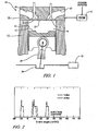
- Fig. 1 is a schematic diagram, in accordance with the present invention.
- Figs. 2 and 3 are graphical depictions related to engine operation, in accordance with the present invention.
- Figs. 4 - 15 are graphical diagrams of quantitative parametric data, in accordance with the present invention.
- FIG. 1 depicts an internal combustion engine 10 which has been constructed in accordance with an embodiment of the invention.
- the invention comprises a method and system to manage and control aspects of engine operation and combustion, and therefore control exhaust emissions.
- the exemplary engine comprises a direct injection, diffusion combustion compression-ignition engine employing a four-stroke operation wherein each engine combustion cycle comprises 720 degrees of angular rotation of a crankshaft divided into four 180-degree stages of intake-compression-expansion-exhaust, which are descriptive of piston movement in each engine cylinder.
- Diffusion combustion is characterized by combustion of fuel immediately upon injection into a combustion chamber with little or no pre-mixing of the fuel with air in the combustion chamber.
- the internal combustion engine 10 is operatively coupled with an engine control module (ECM) 5 adapted to execute engine control schemes, based upon operator inputs, ambient conditions, and engine operating conditions.
- ECM engine control module
- the exemplary internal combustion engine comprises a multi-cylinder engine, comprising an engine block 13, a head 15, and a crankshaft 34.
- a plurality of cylinders 14 is formed in the block, each cylinder 14 containing a piston 12 operative to move linearly therewithin.
- Each piston 12 is mechanically operably connected to the crankshaft 34 via a piston rod 36, and the crankshaft is mounted to the engine block 13 on main bearings.
- a combustion chamber 16 is formed in each cylinder 14 between the top of each piston 12 and the cylinder head 15. The crankshaft 34 rotates at the main bearings, in response to linear force applied thereto by the piston rods 36, as a result of combustion events in the combustion chambers 16.
- the head 15 contains one or more air inlet ports 18 and intake valves 20, one or more exhaust ports 22 and exhaust valves 24, and a fuel injector 38 operable to deliver fuel directly into the combustion chamber 16. Opening and closing of the intake valves 20 is controlled by a camshaft, the action of which controls inflow of air to the combustion chamber. Opening and closing of the exhaust valves 24 is controlled by a camshaft, the action of which controls exhaust of combustion products out of the combustion chamber.
- the fuel injector 38 is preferably an element of a common-rail fuel injection system further comprising a high-pressure fuel pump operative to deliver high-pressure (e.g., 1,800 bar/ 180 MPa) fuel to each injector.
- the fuel injector comprises one of a solenoid-actuated or piezoelectric-actuated device with a nozzle placed through an opening in the head to inject pressurized fuel into the combustion chamber.
- the injector nozzle comprises a fuel injector tip characterized by number of openings, spray angle, and flow number, representing a volumetric flow rate at a given pressure.
- An exemplary fuel injector tip, described hereinafter, comprises a 7-hole, 158-deg spray angle having a 405 flow number (in cc/30-s @ 100 bar).
- Fuel injector characteristics further comprise minimum and maximum flowrates and dynamic range.
- the ECM 5 is operative to individually and selectively control the fuel injectors to deliver precise quantities of fuel at specific times during ongoing engine operation.
- the ECM 5 preferably comprises a central processing unit signally electrically connected to volatile and non-volatile memory devices via data buses.
- the ECM is signally connected to sensing devices and operatively connected to output devices to monitor and control engine operation and operator inputs.
- the output devices preferably include subsystems necessary for proper control and operation of the engine, comprising the fuel injection system, and other devices including an exhaust gas recirculation (EGR) system (not shown).
- the engine sensing devices include devices operable to monitor engine operation, external conditions, and operator demand, e.g., operator torque requests. Control algorithms are typically executed during preset loop cycles such that each is executed at least once per loop cycle. Loop cycles are executed each 3, 6, 15, 25 and 100 milliseconds for typical engine operation.
- the description of the ECM 5 and the internal combustion engine is meant to be illustrative, and not restrictive to the invention.
- the invention comprises a method for controlling injection of fuel into the combustion chamber is detailed.
- the method comprises determining a quantity of fuel to inject during each combustion cycle, based upon engine operating conditions and operator demand for torque.
- a high load engine operation e.g., engine operation in a range of eight to sixteen bar BMEP or greater
- fuel is injected into each combustion chamber 16 by executing a triple injection, wherein three successive fuel injection events occur during each combustion cycle.
- There is a minimum engine operating point for permitting triple injection below which it is not feasible to execute triple injection. This minimum engine operating point is driven by dynamic range of the fuel injectors and the ability of the system to precisely control fuel injection and engine operation.
- Dwell times between the successive fuel injection events are substantially equal, and, quantities of fuel injected during each of the fuel injection events are substantially equal.
- Dwell time is defined to be an elapsed time between an end of an injection event and initiation of a subsequent fuel injection event, during a combustion cycle.
- a graphical depiction of exemplary timing of three injection events of the triple injection (3-INJ) is provided, and compared to a single injection event (1-INJ) for delivering the same quantity of fuel.
- the exemplary engine is operating at an operating point comprising 2115 revolutions per minute (RPM), at a manifold pressure of 215 kPa, absolute, and brake mean-effective-pressure (BMEP) of 8 bar, and the data depicted is an undimensioned signal representing electrical current flow to fuel injector 38 as a function of engine crank angle degrees around top-dead-center (CA° aTDC).
- the single injection (1-INJ) comprises a conventional injection event, wherein the entire quantity of fuel scheduled for delivery to the combustion chamber during the engine cycle is injected.
- the exemplary single injection event preferably occurs immediately after top-dead-center (TDC) during the expansion stroke, shown herein starting at about six crank-angle degrees after top-dead-center (6 CA° aTDC) for the specific cylinder.
- TDC top-dead-center
- 6 CA° aTDC six crank-angle degrees after top-dead-center
- the magnitude of the fuel injection pulsewidth is determined by algorithms resident in the ECM 5 to deliver the requisite quantity of fuel to the combustion chamber based upon a predetermined calibration.
- the triple injection (3-INJ) comprises three successive fuel injection events, wherein a third of the quantity of fuel scheduled for delivery to the combustion chamber during the engine cycle is injected during each injection event, and a predetermined dwell time between the injection events.
- the magnitude of each of the first, second, and third fuel injection pulsewidths is determined by algorithms resident in the ECM to deliver the requisite quantity of fuel to the combustion chamber based upon a predetermined calibration. Initiation of the first fuel injection event typically occurs near top-dead-center during the compression stroke, shown herein with the first injection event beginning at about twelve crank-angle degrees before top-dead-center (12 CA° bTDC) for the specific cylinder.
- the dwell time is set at about 1000 microseconds in this example.
- Initiation of the first fuel injection event of the triple injection is preferably determined based upon a crank angle at which 50% of the quantity of fuel injected during the combustion cycle for the three injection event is substantially the same as for the single injection event for injecting the quantity of fuel.
- Representative data depicting preferred crank angles at which 50% of the fuel has been injected for a specific engine operating point is provided in Fig. 15 .
- Preferred crank angle at which 50% of the fuel has been injected is readily determinable for a single injection event, based upon analytical and empirical data related to operation of a specific engine configuration.
- crank angle at which to initiate the first fuel injection event for the triple injection can be readily determined by an algorithm resident in the ECM based upon the triple injection event injector pulsewidths for the combustion cycle and the dwell time, with adjustments for lag times related to fuel heat release and other effects.
- Preferred crank angles at which 50% of the fuel has been injected for a specific engine operating point is provided in Fig. 15 , showing the 50% injection point for the triple injection event to lag the 50% injection point for the single injection by about 0.9 crank-angle degrees (CA°).
- FIG. 3 through 14 datagraphs are shown depicting various aspects of engine operation for the triple injection as compared to single and dual injection events similarly executed.
- the datagraphs comprise representative results obtained from testing conducted on an exemplary direct-injection diesel combustion engine described with reference to Fig. 1 , operating under the conditions described hereinbelow.
- the exemplary engine has further dimensions and operating conditions described with reference to Table 1.
- Table 1 Bore 103 mm Stroke 99 mm Engine Speed 2115 RPM BMEP 8 bar Manifold Pressure 215 kPa absolute Fuel Rail Pressure 1800 bar Injector Tip (# of holes) 7 quantity Injector Tip Flow Number 405 cc/30s @100bar NO x Emission Index 1.5 g/kg fuel
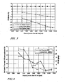
- timing of each of the first, second, and third fuel injection events for the triple injection are graphically depicted, with varying dwell times, for the exemplary engine operating under conditions described with reference to Table 1.
- Timing of the first injection event is held constant at 10 CA° bTDC, and injection times of the second and third injection events are shown, in crank angle degrees, based upon varying dwell times from 600 to 1250 microseconds, when the engine is operating at 2115 RPM.
- the operating condition described in Table 1 comprises a high load condition of about 8-bar BMEP and 2115 RPM engine speed.
- Engine parameters include a high fuel rail pressure of 1800 bar and the fuel injector tip comprising a 7-hole, 158-deg spray angle having a 405 flow number (in cc/30-s @ 100 bar).
- NO x emission index is held constant at 1.5-g/kg fuel by adjusting EGR flow rate.
- Fig. 4 data is shown comprising results for operating the exemplary engine as described with reference to Table 1 over the range of dwell times, wherein particulate mass emission index (PM EI) and indicated thermal efficiency (ITE) are monitored.
- the PM EI is measured in units of grams of PM per kilogram of fuel (g/kg), calculated from a measured filter smoke number (FSN).
- the indicated thermal efficiency (ITE) is measured in percent, and is based on measured fuel flow and firing and motoring torques. Both PM and ITE are demonstrated to vary with the dwell time, with PM and ITE both decreasing with increasing dwell time. There is a preferred range of dwell magnitude from about 950 to 1100 microseconds for this embodiment to reach reasonable low PM values without unduly lowering thermal efficiency.
- emissions results are graphically depicted over the range of dwell times for the testing described with reference to Table 1.
- Emissions results comprising emissions indices (EI) for hydrocarbons (HC), carbon monoxide (CO), and nitrides of oxygen (NO x ) are depicted.
- the results indicate HC EI and CO EI tend to increase with increasing dwell.
- NO x EI was held constant at 1.5g/kg and PM was held constant at 0.3 g/kg.
- the effects upon HC and CO are acceptable, and the results indicate the exemplary engine to be readily compliant with current and upcoming regulations.
- Figs. 4 and 5 indicate that there is an optimum dwell time between the end of the first injection event and the beginning of the second injection event at which high engine efficiency balances with low PM emissions, and reasonable HC and CO emissions. Similarly, there is an optimum dwell time between the end of the second injection event and the beginning of the third injection event. Optimum dwell times between injections may be influenced by various factors.
- fuel injection system characteristics which affect fuel flow, including, e.g., injector hole size, rail pressure variation, and injector targeting; combustion chamber bowl geometry and swirl level at various operating conditions; fuel burning rate as influenced by injection rate due to the injector nozzle flow number and rail pressure; fuel quantity per injection and total injected fuel quantity; opening and closing characteristics of the particular common rail fuel injector; fuel properties including, e.g., cetane number, distillation temperature range, viscosity, density; and, density of air and EGR mixture as affected by intake manifold pressure, compression ratio, and mixture temperature.
- exemplary data comprising cylinder pressures and mass fraction of fuel burned are graphically depicted over pertinent range of engine crank angle during the compression and expansion cycles.
- the exemplary data depicts results from engine testing at the engine operating condition described with reference to Table 1, with results for triple (3-INJ) injection events compared to results for single (1-INJ) and dual (2-INJ) injection events with the total quantity of fuel injected during each combustion cycle for the single, dual, and triple injection events.
- cylinder pressure traces are depicted for each of the single, dual, and triple injection strategies.
- Fig. 7 cumulative mass-fraction of fuel burned is depicted for each of the single, dual, and triple injection strategies.
- the cumulative mass fraction burned traces illustrate distinct phases of combustion for each of the injection strategies.
- the optimal timing for dual injections results in the two pulses centered about the single injection pulse.
- the optimal timing for triple injections also results in the three pulses centered about the single injection pulse.
- the cumulative mass fraction burned curves clearly demonstrate an effect of the three stages of combustion for the triple injection case, compared to the single and dual injection cases.
- ITE for combustion with single, dual, and triple injection events indicate improvements in the indicated thermal efficiency using the triple injection event, as compared to the dual and single-injection combustion at equally low values of NO x and PM emissions.
- Dual injection events and corresponding dual-stage burning is shown to have a 4% efficiency advantage over single injection events and single-stage burning.
- Triple- injection events with triple-stage burning boosts efficiency advantage to about 8% over single-stage burning for the exemplary engine and operating conditions.
- HC EI and CO EI emissions increase with increasing stages of combustion, but the magnitudes are small.
- Fig. 11 there is a correspondingly minimal effect on combustion efficiency, showing a lowering of the combustion efficiency by a magnitude of about 0.5%.
- This effect on combustion efficiency is not reflected by engine thermal efficiency or by engine fuel consumption, as demonstrated with reference to Figs. 11 and 14 .
- Fig. 12 gains in the indicated thermal efficiency from triple-injection as compared to dual-injection and single injection can be attributed to more advanced phasing of combustion, as demonstrated by location of the 50% burn-point, which advances toward top-dead-center with triple injection. For two injections, the phasing advances about one half ways between the single-injection and triple injection case. Furthermore, as shown with reference to Fig.
- BFSC brake-specific fuel consumption
Landscapes
- Engineering & Computer Science (AREA)
- Chemical & Material Sciences (AREA)
- Combustion & Propulsion (AREA)
- Mechanical Engineering (AREA)
- General Engineering & Computer Science (AREA)
- Electrical Control Of Air Or Fuel Supplied To Internal-Combustion Engine (AREA)
Claims (9)
- Procédé pour commander l'injection de carburant dans un moteur à combustion interne (10), comprenant les étapes consistant à :déterminer une quantité de carburant à injecter dans une chambre de combustion (16) pendant un cycle de combustion ;exécuter trois événements d'injection de carburant (3-INJ) ayant des temps de séjour entre eux pour injecter la quantité de carburant dans la chambre de combustion (16) pendant le cycle de combustion ; etfixer le premier temps de séjour sensiblement égal au second temps de séjour ;caractérisé en ce queles trois événements d'injection de carburant (3-INJ) sont exécutés sélectivement uniquement si l'on détermine que le moteur (10) fonctionne dans une plage de fonctionnement à forte charge,des quantités égales de carburant sont injectées pendant chacun des trois événements d'injection de carburant (3-INJ), eton détermine un angle de vilebrequin pour démarrer le premier événement d'injection de carburant en se basant sur un angle de vilebrequin auquel 50 % de la quantité de carburant est injectée pendant le cycle de combustion pour les trois événements de combustion (3-INJ) est le même que pour qu'un unique événement d'injection (1-INJ) injecte la quantité de carburant.
- Procédé selon la revendication 1, comprenant en outre de démarrer le premier événement d'injection de carburant pendant une course de compression immédiatement avant un point mort haut du déplacement du piston.
- Procédé selon la revendication 1, dans lequel le moteur à combustion interne (10) comprend un moteur à injection directe et à combustion par diffusion.
- Procédé selon la revendication 1, dans lequel la quantité de carburant injectée dans la chambre de combustion (16) pendant le cycle de combustion est déterminée en se basant sur les conditions de fonctionnement du moteur et sur une demande d'un opérateur concernant un couple.
- Procédé selon la revendication 1, dans lequel l'étape consistant à déterminer que le moteur (10) fonctionne dans une plage de fonctionnement à forte charge comprend de déterminer que le moteur (10) fonctionne à une pression moyenne effective supérieure à environ huit bars.
- Moteur à combustion interne (10), comprenant :un moteur à combustion par diffusion équipé d'un système d'injection de carburant comprenant un système de carburant à haute pression etune pluralité d'injecteurs de carburant (38), chacun adapté à injecter du carburant directement dans une chambre de combustion (16) du moteur (10) ; etun contrôleur (5), adapté à :surveiller le fonctionnement du moteur et déterminer un point de fonctionnement du moteur ;déterminer une quantité de carburant à injecter dans l'une des chambres de combustion pendant un cycle de combustion ; etactionner sélectivement l'un des injecteurs de carburant pour exécuter trois événements d'injection de carburant (3-INJ) pour fournir la quantité déterminée de carburant à la chambre de combustion (16) pendant le cycle de combustion, comprenant :i) l'exécution des trois événements d'injection de carburant (3-INJ) avec des temps de séjour entre eux ;ii) la fixation du premier temps de séjour sensiblement égal au second temps le séjour ;caractérisé en ce quel'actionnement sélectif comprend :- l'exécution sélective des trois événements d'injection de carburant (3-INJ) uniquement si l'on détermine que le moteur (10) fonctionne dans une plage de fonctionnement à forte charge ;- l'injection de quantités égales de carburant pendant chacun des trois événements d'injection de carburant (3-INJ) ; et- la détermination d'un angle de vilebrequin pour démarrer le premier événement d'injection de carburant en se basant sur un angle de vilebrequin auquel 50 % de la quantité de carburant est injectée pendant le cycle de combustion pour les trois événements d'injection est sensiblement le même que pour qu'un unique événement d'injection injecte la quantité de carburant.
- Moteur à combustion interne selon la revendication 6, dans lequel le moteur à combustion par diffusion (10) comprend un moteur à injection directe et à allumage par compression.
- Moteur à combustion interne selon la revendication 6, dans lequel le système de carburant à haute pression est prévu pour fonctionner à une pression de carburant allant jusqu'à 1800 bars.
- Moteur à combustion interne selon la revendication 6, comprenant en outre que chaque injecteur de carburant (38) est caractérisé par un débit minimum ; et que le seuil prédéterminé pour le point de fonctionnement du moteur est basé sur un fonctionnement du moteur qui comprend trois événements d'injection de carburant (3-INJ) au débit minimum pendant le cycle de combustion.
Applications Claiming Priority (1)
| Application Number | Priority Date | Filing Date | Title |
|---|---|---|---|
| US11/535,509 US7467615B2 (en) | 2006-09-27 | 2006-09-27 | Method and apparatus to control fuel injection |
Publications (2)
| Publication Number | Publication Date |
|---|---|
| EP1908948A1 EP1908948A1 (fr) | 2008-04-09 |
| EP1908948B1 true EP1908948B1 (fr) | 2012-10-24 |
Family
ID=38935969
Family Applications (1)
| Application Number | Title | Priority Date | Filing Date |
|---|---|---|---|
| EP07018378A Ceased EP1908948B1 (fr) | 2006-09-27 | 2007-09-19 | Procédé et appareil pour contrôler l'injection de carburant |
Country Status (2)
| Country | Link |
|---|---|
| US (1) | US7467615B2 (fr) |
| EP (1) | EP1908948B1 (fr) |
Families Citing this family (12)
| Publication number | Priority date | Publication date | Assignee | Title |
|---|---|---|---|---|
| US7464689B2 (en) * | 2005-10-12 | 2008-12-16 | Gm Global Technology Operations, Inc. | Method and apparatus for controlling fuel injection into an engine |
| EP1903204A1 (fr) * | 2006-09-12 | 2008-03-26 | Siemens Aktiengesellschaft | Procédé pour la réduction des émissions de polluants et de la consommation d'un moteur |
| US7765053B2 (en) * | 2007-08-10 | 2010-07-27 | Gm Global Technology Operations, Inc. | Multi-injection combustion cycle systems for SIDI engines |
| JP4404154B2 (ja) * | 2008-06-09 | 2010-01-27 | トヨタ自動車株式会社 | 内燃機関の燃料噴射制御装置 |
| US8195378B2 (en) * | 2008-07-28 | 2012-06-05 | Cummins Inc. | Emissions reductions through multiple fuel injection events |
| US8364380B2 (en) * | 2009-08-13 | 2013-01-29 | GM Global Technology Operations LLC | Method and system for fuel injection control to reduce variation |
| US8813690B2 (en) * | 2009-10-30 | 2014-08-26 | Cummins Inc. | Engine control techniques to account for fuel effects |
| EP2383454A1 (fr) * | 2010-04-27 | 2011-11-02 | C.R.F. Società Consortile per Azioni | Formage du débit d'injection de carburant dans un moteur à combustion interne |
| DE102012011149A1 (de) * | 2012-06-05 | 2013-12-05 | Abb Turbo Systems Ag | Einspritzsystem für kompressionsgezündete Dieselmotoren |
| US8985089B2 (en) * | 2012-07-25 | 2015-03-24 | The United States Of America, As Represented By The Administrator Of The U.S. Environmental Protection Agency | Low temperature dual fuel combustion utilizing diesel and methanol fuels |
| US9453474B2 (en) | 2013-06-12 | 2016-09-27 | Ford Global Technologies, Llc | Method for operating a direct fuel injection system |
| WO2015039095A1 (fr) * | 2013-09-16 | 2015-03-19 | Cummins Inc. | Système pour l'ajustement d'un signal de commande d'actionneur d'injecteur de carburant lors d'un événement d'injection de carburant |
Family Cites Families (10)
| Publication number | Priority date | Publication date | Assignee | Title |
|---|---|---|---|---|
| US3792692A (en) | 1972-03-22 | 1974-02-19 | Teledyne Ind | Fuel injection device |
| US5265562A (en) | 1992-07-27 | 1993-11-30 | Kruse Douglas C | Internal combustion engine with limited temperature cycle |
| JP2001055951A (ja) * | 1999-08-18 | 2001-02-27 | Mazda Motor Corp | ディーゼルエンジンの燃料噴射制御装置 |
| US6467452B1 (en) | 2000-07-13 | 2002-10-22 | Caterpillar Inc | Method and apparatus for delivering multiple fuel injections to the cylinder of an internal combustion engine |
| DE60212079T2 (de) * | 2001-02-20 | 2006-12-07 | Isuzu Motors Ltd. | Verfahren zur Steuerung der Kraftstoffeinspritzung für Dieselmotoren und Regenerationssteuerungsverfahren für Abgasnachbehandlungsvorrichtung |
| ITTO20010786A1 (it) | 2001-08-03 | 2003-02-03 | Fiat Ricerche | Metodo di autoinnesco della rigenerazione di un filtro particolato per un motore diesel ad iniezione diretta provvisto di un impianto di ini |
| ITTO20030987A1 (it) | 2003-12-09 | 2005-06-10 | Fiat Ricerche | Metodo di controllo di un motore ad accensione spontanea provvisto di un impianto di iniezione a collettore comune durante la rigenerazione del filtro del particolato. |
| CN1950489B (zh) | 2004-05-14 | 2010-10-27 | 埃克森美孚研究工程公司 | 控制均匀负荷直接喷射压燃式发动机废气排放的方法 |
| EP1653069B1 (fr) * | 2004-10-26 | 2018-03-21 | Volvo Car Corporation | Méthode et système de combustion pour améliorer des caractéristiques de combustion pour un moteur d'injection directe à diesel |
| JP2007162585A (ja) | 2005-12-14 | 2007-06-28 | Nissan Motor Co Ltd | エンジンの燃料噴射制御装置及び燃料噴射制御方法 |
-
2006
- 2006-09-27 US US11/535,509 patent/US7467615B2/en not_active Expired - Fee Related
-
2007
- 2007-09-19 EP EP07018378A patent/EP1908948B1/fr not_active Ceased
Also Published As
| Publication number | Publication date |
|---|---|
| US7467615B2 (en) | 2008-12-23 |
| US20080072872A1 (en) | 2008-03-27 |
| EP1908948A1 (fr) | 2008-04-09 |
Similar Documents
| Publication | Publication Date | Title |
|---|---|---|
| EP1908948B1 (fr) | Procédé et appareil pour contrôler l'injection de carburant | |
| CN101932816B (zh) | 控制火花点火式直喷内燃机中的模式转换的方法和装置 | |
| JP5569468B2 (ja) | 火花点火式エンジンの制御装置 | |
| US6840211B2 (en) | Diesel engine | |
| US7464689B2 (en) | Method and apparatus for controlling fuel injection into an engine | |
| US7610900B2 (en) | Method and apparatus for operating a spark-ignited direct fuel injection engine | |
| CN101903626B (zh) | 用于将燃料喷射到压缩点火发动机中的方法和设备 | |
| EP1965065A1 (fr) | Procédé de contrôle de la combustion de carburant dans un moteur diesel par injections multiples via un système d'injection de carburant à rail commun | |
| CN102822485B (zh) | 内燃机的燃烧控制装置 | |
| CN102165171A (zh) | 内燃机的燃料喷射控制装置 | |
| WO2011048676A1 (fr) | Dispositif de commande de combustion pour moteur à combustion interne | |
| US20170234249A1 (en) | Control system for internal combustion engine, internal combustion engine and method of controlling internal combustion engine | |
| CN101939524B (zh) | 内燃机的燃料喷射控制装置 | |
| EP2511505A2 (fr) | Dispositif de contrôle de combustion | |
| JP2014020211A (ja) | 筒内噴射式エンジンの燃料噴射制御装置 | |
| JP5561226B2 (ja) | 火花点火式ガソリンエンジンの制御装置 | |
| KR20060015466A (ko) | 디젤 엔진의 작동 모드 및 연소 모드를 최적화하기 위한방법 | |
| US7441537B2 (en) | Method and apparatus to control combustion in a spray-guided direct injection spark-ignited engine | |
| JP2011089445A (ja) | 内燃機関の燃焼制御装置 | |
| JP5170317B2 (ja) | 内燃機関の燃料噴射制御装置 | |
| JP2012215096A (ja) | 火花点火式エンジン用高圧燃料ポンプの異常判定方法および火花点火式エンジンの制御装置 | |
| JP2007032473A (ja) | 筒内噴射自着火式エンジンの燃焼制御装置 | |
| JP2002038995A (ja) | ディーゼルエンジンの燃料噴射装置 | |
| JP2002038990A (ja) | ディーゼルエンジンの燃料噴射装置 | |
| JP2002054489A (ja) | ディーゼルエンジンの燃料噴射制御装置 |
Legal Events
| Date | Code | Title | Description |
|---|---|---|---|
| PUAI | Public reference made under article 153(3) epc to a published international application that has entered the european phase |
Free format text: ORIGINAL CODE: 0009012 |
|
| AK | Designated contracting states |
Kind code of ref document: A1 Designated state(s): AT BE BG CH CY CZ DE DK EE ES FI FR GB GR HU IE IS IT LI LT LU LV MC MT NL PL PT RO SE SI SK TR |
|
| AX | Request for extension of the european patent |
Extension state: AL BA HR MK RS |
|
| 17P | Request for examination filed |
Effective date: 20080514 |
|
| 17Q | First examination report despatched |
Effective date: 20080612 |
|
| AKX | Designation fees paid |
Designated state(s): DE |
|
| RAP1 | Party data changed (applicant data changed or rights of an application transferred) |
Owner name: GM GLOBAL TECHNOLOGY OPERATIONS LLC |
|
| GRAP | Despatch of communication of intention to grant a patent |
Free format text: ORIGINAL CODE: EPIDOSNIGR1 |
|
| GRAS | Grant fee paid |
Free format text: ORIGINAL CODE: EPIDOSNIGR3 |
|
| GRAA | (expected) grant |
Free format text: ORIGINAL CODE: 0009210 |
|
| AK | Designated contracting states |
Kind code of ref document: B1 Designated state(s): DE |
|
| REG | Reference to a national code |
Ref country code: DE Ref legal event code: R096 Ref document number: 602007026217 Country of ref document: DE Effective date: 20121220 |
|
| PLBE | No opposition filed within time limit |
Free format text: ORIGINAL CODE: 0009261 |
|
| STAA | Information on the status of an ep patent application or granted ep patent |
Free format text: STATUS: NO OPPOSITION FILED WITHIN TIME LIMIT |
|
| 26N | No opposition filed |
Effective date: 20130725 |
|
| REG | Reference to a national code |
Ref country code: DE Ref legal event code: R097 Ref document number: 602007026217 Country of ref document: DE Effective date: 20130725 |
|
| PGFP | Annual fee paid to national office [announced via postgrant information from national office to epo] |
Ref country code: DE Payment date: 20190903 Year of fee payment: 13 |
|
| REG | Reference to a national code |
Ref country code: DE Ref legal event code: R119 Ref document number: 602007026217 Country of ref document: DE |
|
| PG25 | Lapsed in a contracting state [announced via postgrant information from national office to epo] |
Ref country code: DE Free format text: LAPSE BECAUSE OF NON-PAYMENT OF DUE FEES Effective date: 20210401 |