EP1908953B1 - Dispositif d'injection de carburant - Google Patents
Dispositif d'injection de carburant Download PDFInfo
- Publication number
- EP1908953B1 EP1908953B1 EP07114426A EP07114426A EP1908953B1 EP 1908953 B1 EP1908953 B1 EP 1908953B1 EP 07114426 A EP07114426 A EP 07114426A EP 07114426 A EP07114426 A EP 07114426A EP 1908953 B1 EP1908953 B1 EP 1908953B1
- Authority
- EP
- European Patent Office
- Prior art keywords
- chamber
- pressure
- pressure booster
- fuel injection
- section
- Prior art date
- Legal status (The legal status is an assumption and is not a legal conclusion. Google has not performed a legal analysis and makes no representation as to the accuracy of the status listed.)
- Not-in-force
Links
- 238000002347 injection Methods 0.000 title claims abstract description 42
- 239000007924 injection Substances 0.000 title claims abstract description 42
- 239000000446 fuel Substances 0.000 title claims abstract description 32
- 230000008878 coupling Effects 0.000 claims description 12
- 238000010168 coupling process Methods 0.000 claims description 12
- 238000005859 coupling reaction Methods 0.000 claims description 12
- 238000002485 combustion reaction Methods 0.000 claims description 5
- 239000000470 constituent Substances 0.000 claims 1
- 230000036316 preload Effects 0.000 claims 1
- 239000007921 spray Substances 0.000 claims 1
- 238000000034 method Methods 0.000 description 5
- 230000008901 benefit Effects 0.000 description 4
- 230000008569 process Effects 0.000 description 4
- 238000007789 sealing Methods 0.000 description 3
- 230000004913 activation Effects 0.000 description 2
- 238000010276 construction Methods 0.000 description 1
- 230000001419 dependent effect Effects 0.000 description 1
- 230000008030 elimination Effects 0.000 description 1
- 238000003379 elimination reaction Methods 0.000 description 1
- 239000003344 environmental pollutant Substances 0.000 description 1
- 238000004519 manufacturing process Methods 0.000 description 1
- 231100000719 pollutant Toxicity 0.000 description 1
- 230000008092 positive effect Effects 0.000 description 1
- 230000009467 reduction Effects 0.000 description 1
- 239000000243 solution Substances 0.000 description 1
Images

Classifications
-
- F—MECHANICAL ENGINEERING; LIGHTING; HEATING; WEAPONS; BLASTING
- F02—COMBUSTION ENGINES; HOT-GAS OR COMBUSTION-PRODUCT ENGINE PLANTS
- F02M—SUPPLYING COMBUSTION ENGINES IN GENERAL WITH COMBUSTIBLE MIXTURES OR CONSTITUENTS THEREOF
- F02M57/00—Fuel-injectors combined or associated with other devices
- F02M57/02—Injectors structurally combined with fuel-injection pumps
- F02M57/022—Injectors structurally combined with fuel-injection pumps characterised by the pump drive
- F02M57/025—Injectors structurally combined with fuel-injection pumps characterised by the pump drive hydraulic, e.g. with pressure amplification
-
- F—MECHANICAL ENGINEERING; LIGHTING; HEATING; WEAPONS; BLASTING
- F02—COMBUSTION ENGINES; HOT-GAS OR COMBUSTION-PRODUCT ENGINE PLANTS
- F02M—SUPPLYING COMBUSTION ENGINES IN GENERAL WITH COMBUSTIBLE MIXTURES OR CONSTITUENTS THEREOF
- F02M47/00—Fuel-injection apparatus operated cyclically with fuel-injection valves actuated by fluid pressure
- F02M47/02—Fuel-injection apparatus operated cyclically with fuel-injection valves actuated by fluid pressure of accumulator-injector type, i.e. having fuel pressure of accumulator tending to open, and fuel pressure in other chamber tending to close, injection valves and having means for periodically releasing that closing pressure
- F02M47/027—Electrically actuated valves draining the chamber to release the closing pressure
-
- F—MECHANICAL ENGINEERING; LIGHTING; HEATING; WEAPONS; BLASTING
- F02—COMBUSTION ENGINES; HOT-GAS OR COMBUSTION-PRODUCT ENGINE PLANTS
- F02M—SUPPLYING COMBUSTION ENGINES IN GENERAL WITH COMBUSTIBLE MIXTURES OR CONSTITUENTS THEREOF
- F02M57/00—Fuel-injectors combined or associated with other devices
- F02M57/02—Injectors structurally combined with fuel-injection pumps
- F02M57/022—Injectors structurally combined with fuel-injection pumps characterised by the pump drive
- F02M57/025—Injectors structurally combined with fuel-injection pumps characterised by the pump drive hydraulic, e.g. with pressure amplification
- F02M57/026—Construction details of pressure amplifiers, e.g. fuel passages or check valves arranged in the intensifier piston or head, particular diameter relationships, stop members, arrangement of ports or conduits
-
- F—MECHANICAL ENGINEERING; LIGHTING; HEATING; WEAPONS; BLASTING
- F02—COMBUSTION ENGINES; HOT-GAS OR COMBUSTION-PRODUCT ENGINE PLANTS
- F02M—SUPPLYING COMBUSTION ENGINES IN GENERAL WITH COMBUSTIBLE MIXTURES OR CONSTITUENTS THEREOF
- F02M63/00—Other fuel-injection apparatus having pertinent characteristics not provided for in groups F02M39/00 - F02M57/00 or F02M67/00; Details, component parts, or accessories of fuel-injection apparatus, not provided for in, or of interest apart from, the apparatus of groups F02M39/00 - F02M61/00 or F02M67/00; Combination of fuel pump with other devices, e.g. lubricating oil pump
- F02M63/0012—Valves
- F02M63/0014—Valves characterised by the valve actuating means
- F02M63/0015—Valves characterised by the valve actuating means electrical, e.g. using solenoid
- F02M63/0026—Valves characterised by the valve actuating means electrical, e.g. using solenoid using piezoelectric or magnetostrictive actuators
-
- F—MECHANICAL ENGINEERING; LIGHTING; HEATING; WEAPONS; BLASTING
- F02—COMBUSTION ENGINES; HOT-GAS OR COMBUSTION-PRODUCT ENGINE PLANTS
- F02M—SUPPLYING COMBUSTION ENGINES IN GENERAL WITH COMBUSTIBLE MIXTURES OR CONSTITUENTS THEREOF
- F02M63/00—Other fuel-injection apparatus having pertinent characteristics not provided for in groups F02M39/00 - F02M57/00 or F02M67/00; Details, component parts, or accessories of fuel-injection apparatus, not provided for in, or of interest apart from, the apparatus of groups F02M39/00 - F02M61/00 or F02M67/00; Combination of fuel pump with other devices, e.g. lubricating oil pump
- F02M63/0012—Valves
- F02M63/0031—Valves characterized by the type of valves, e.g. special valve member details, valve seat details, valve housing details
- F02M63/0045—Three-way valves
-
- F—MECHANICAL ENGINEERING; LIGHTING; HEATING; WEAPONS; BLASTING
- F02—COMBUSTION ENGINES; HOT-GAS OR COMBUSTION-PRODUCT ENGINE PLANTS
- F02M—SUPPLYING COMBUSTION ENGINES IN GENERAL WITH COMBUSTIBLE MIXTURES OR CONSTITUENTS THEREOF
- F02M2200/00—Details of fuel-injection apparatus, not otherwise provided for
- F02M2200/70—Linkage between actuator and actuated element, e.g. between piezoelectric actuator and needle valve or pump plunger
- F02M2200/703—Linkage between actuator and actuated element, e.g. between piezoelectric actuator and needle valve or pump plunger hydraulic
Definitions
- the present invention relates to a fuel injection system for an internal combustion engine, in particular in a motor vehicle.
- an injection pressure can preferably be adapted to a load and a rotational speed of the internal combustion engine.
- a high injection pressure helps to reduce pollutant emissions and at the same time to achieve a high specific power.
- This injection pressure can be further increased by a pressure booster or a pressure booster is arranged in common-rail injection systems.
- an injection valve is known with a pressure booster comprising a stepped piston with two cylindrical sections, which have different diameters and limit a working space and a high-pressure chamber.
- the fuel injection system according to the invention with the features of claim 1 has the advantage that a pressure booster with a simple, coaxial design with an internal pressure booster control chamber through which the pressure booster builds significantly shorter.
- a pressure booster with a stepped piston instead of a pressure booster with a stepped piston, the interior of a hollow piston is relieved to achieve activation of the translation.
- the elimination of the double guide also leads to much simpler components, which are inexpensive to produce.
- a hydraulic connection of the pressure booster control chamber can also be effected simply via corresponding interfaces between different sections of an injector containing the pressure booster, as a result of which further, expensive process steps can be saved.
- the fuel injection system has at least one injector for injecting the fuel, in which the pressure booster is arranged or formed.
- an injector has an injector body, which consists essentially of an actuator section, a pressure booster section and a needle section.
- an intermediate plate is arranged between the actuator section and the pressure booster section, while an end plate is arranged on an end of the pressure booster section facing away from the intermediate plate.
- the pressure booster is arranged in the pressure booster section, which has a hollow piston guided in the pressure booster section and a plunger coaxially immersed in the latter, wherein the two pistons delimit an internal pressure booster control chamber.
- An annular translator chamber of the pressure booster in which the high injection pressure is generated due to an adjustment of the hollow piston in the direction of the end plate, is thereby axially limited by the hollow piston and the end plate, while a radial boundary of the booster chamber is given by the pressure booster section and the plunger.
- the needle section is arranged with a nozzle chamber and a nozzle needle which can be adjusted in height, the translator chamber being connected to the nozzle chamber via a hydraulic path.
- the nozzle space for opening the nozzle needle can be connected to a return line which is unpressurized relative to the system pressure, so that indirectly via the nozzle chamber the interrupter space can also be connected to the return line.
- the actuator section limits a pressurized space under system pressure, in which an actuator is arranged.
- Piezo-actuator within the injector in Aktorabites creates a particularly space-minimizing construction, which also eliminates the need to arrange an actuator outside of the injector and thus a complex connection of the same with the injector.
- the actuator is braced via a spring device in the pressure chamber of Aktorabiteses and arranged fixed in position.
- a coupling path is arranged, which hydraulically connects the pressure chamber of the Aktorabitess with a, located in the pressure booster section on a side facing away from the pressure booster control chamber side of the hollow piston, the hollow piston rear.
- the intermediate plate can be used as a coupling member between the actuator section and the pressure booster section, wherein the system pressure is always applied by the coupling path both in the pressure chamber and in the hollow piston rear space.
- the above-mentioned actuator actuates in the activated state a stroke adjustable arranged in Aktorabflat valve piston having a first and a second valve seat, wherein in a first stroke end of the first valve seat closed and the second valve seat is open and opened in a second stroke end of the first valve seat and the second valve seat closed is.
- the actuator acts directly on a coupler space on the valve piston and adjusts this at least between its two stroke end positions.
- the first stroke end position of the first valve seat In the first stroke end position of the first valve seat is closed, whereby a hydraulic connection between the pressure translator control chamber and the non-pressurized return is interrupted.
- the second valve seat In contrast, the second valve seat is open, so that a pressure equalization between the pressure booster control chamber and the hollow piston rear space and thus via the coupling path with the pressure chamber and a pressure source connected thereto is possible.
- the first valve seat in its second stroke end position, the first valve seat is opened, so that a hydraulic connection between the pressure booster control chamber and the non-pressurized return is provided, while a connection between the pressure booster control chamber and the hollow piston rear space is interrupted.
- the valve piston with its two valve seats offers the great advantage of being able to perform a control function structurally simple and at the same time to allow extremely short switching times.
- the nozzle needle is designed so that pressurization of the nozzle chamber supports an opening movement of the nozzle needle.
- the nozzle needle has an inflow surface, which faces the nozzle chamber and which leads to an opening movement of the nozzle needle when pressure is applied to the nozzle chamber.
- a nozzle needle spring which is arranged in a needle closing space and which biases the nozzle needle into its closed position for the nozzle needle to move into its closed position and to close the at least one injection hole.
- the hydraulic pressure in the nozzle chamber is used together with a nozzle needle spring in a structurally ingenious way to control the opening and closing movement of the nozzle needle, due to the coupling of the nozzle needle spring with the counteracting pressure in Nozzle space an extremely fast switching operation can be achieved.
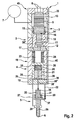
- Fig. 1 to 3 includes a fuel injection system 45 according to the invention at least one injector 1, wherein the fuel injection system 45 may be arranged in particular in a motor vehicle and is used to supply fuel to the individual cylinders of an internal combustion engine. If several injectors 1 are connected to a common high-pressure fuel line or to a common pressure source 7, it is a so-called common-rail system.
- the injector 1 has an injector body 2, which essentially comprises an actuator section 3, a pressure booster section 4 and a needle section 5.
- the actuator section 3 and the pressure booster section 4 are not using one here illustrated connecting element, in particular after the manner of a union nut, firmly connected.
- the injector body 2 In its needle section 5, the injector body 2 has at least one injection hole 6, through which fuel can be injected into an injection space, not shown. Connected to the injector 1 on the one hand hydraulically with a pressure accumulator or a pressure source 7 and on the other hand electrically via corresponding lines 8 with an injection control system.
- the injector 1 has an actuator 9, in particular a piezo actuator, which expands in an activated state with regard to its axial longitudinal extent.
- a valve piston 10 is provided, which has a first valve seat 11 and a second valve seat 12 and which is mounted in a stroke-adjustable manner in the injector body 2.
- the valve piston 10 is mounted adjustable in stroke between a first end position and a second stroke end position, wherein according to the Fig. 1 to 3 the first stroke end position is shown. In this first stroke end position, the first valve seat 11 is closed and the second valve seat 12 is opened, while in the second stroke end position the first valve seat 11 is opened and the second valve seat 12 is closed.
- the actuator 9 is arranged in a pressure chamber 13, which is hydraulically connected to the pressure accumulator or the pressure source 7 and is under system pressure. As a result, the actuator 9 can be arranged to save space within the injector body 2, which has a positive effect on a space requirement.
- the valve piston 10 side facing the actuator 9 has a surrounding this sealing sleeve 14, which is biased by a spring means 15 in the direction of the valve piston 10.
- the sealing sleeve 14, the actuator 9 and the valve piston 10 essentially define a coupler space 16, which is usually separated hydraulically from the pressure chamber 13 by the sealing sleeve 14.
- an intermediate plate 17 is arranged between the actuator section 3 and the pressure booster section 4, while an end plate 18 is arranged on the pressure booster section 4 between the pressure booster section 4 and the needle section 5.
- the pressure booster section 4 is thus axially limited on the one hand by the intermediate plate 17 and on the other hand by the end plate 18.
- a pressure booster 19 is arranged, which essentially comprises a hollow piston 20 and an immersed in this plunger 21 and is designed to increase a fuel injection pressure relative to the system pressure.
- the hollow piston 20 is guided in the pressure booster section 4 and serves as a guide for the coaxial plunging into the hollow piston 20 plunger 21. Together, the hollow piston 20 and the plunger 21 define a pressure booster control chamber 22.
- the System pressure On a the pressure booster control chamber 22 side facing away from the hollow piston 20 is the System pressure, wherein the hollow piston 20 defines on this side together with the intermediate plate 17 and the pressure booster section 4 a hollow piston rear space 23.
- a return spring 24 is provided within the hollow piston rear chamber 23 and connected to the hollow piston 20, which biases the hollow piston 20 of the end plate 18 away.
- an opening spring 25 is arranged, which biases the plunger 21 in the extension from the hollow piston 20, that is, down here.
- a booster chamber 26 is provided, which is bounded in the radial direction on the one hand by the pressure booster section 4 and on the other hand by the plunger 21.
- the booster chamber 26 is connected via a hydraulic path 27 with a nozzle chamber 28.
- a needle closing space 30 is arranged on a side facing away from the injection hole 6 of the nozzle needle 29, in which a needle damper piston 31 is arranged hubver tone and which is connected via a hydraulic line 32 for opening the nozzle needle 29 with a relative to the system pressure unpressurized return 33.
- a rear space 34 of the needle damper piston 31 is hydraulically connected to the hydraulic line 32, wherein the hydraulic line 32 may be throttled differently in the area close to the needle closing chamber 30 and near the rear space 34.
- the needle closing chamber 30 is connected via a further hydraulic line 32 'to the booster chamber 26, wherein in the further hydraulic line 32', a check device 36 is arranged, which is continuous only in the direction of the needle closing chamber 30 to the booster chamber 26.
- the needle damper piston 31 according to the Fig. 1 to 3 crossed by an axial passage opening 35, which is closed at one end by the nozzle needle 29 and the other end communicates with the rear space 34.
- a closing spring 37 is arranged, which biases the needle damper piston 31 in the direction of the nozzle needle 29.
- a coupling path 38 which connects the pressure intensifier control chamber 22 with a plunger chamber 39 hydraulically.
- the plunger piston chamber 39 and thus also the pressure booster control chamber 22 are via corresponding coupling paths 38 'and 38 "in the end plate 18 with a running in a wall of the pressure booster section 4 control line 40 and above depending on the position of the valve piston 10 with the hollow piston rear chamber 23 or the return 33rd hydraulically connected.
- a control rod 41 is provided, which penetrates the hollow piston 20 in the axial direction.
- the control rod 41 On its side facing the intermediate plate 17, the control rod 41 is surrounded by a control sleeve 44 which, together with the control rod 41 and the intermediate plate 17, defines a rod control chamber 42.
- a spring device 15 ' is provided, which biases the control sleeve 44 against the intermediate plate 17.
- a passage 43 is provided which connects the rod control chamber 42 hydraulically with the pressure booster control chamber 22.
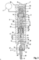
- the coupling path 38 is arranged in the plunger 21, so that a connection between the pressure translator control chamber 22 and the plunger piston chamber 39 is also provided.
- no control line 40 is provided in the wall of the pressure booster section 4.
- the reduction of the pressure in the pressure booster control chamber 22 causes a downward movement of the hollow piston 20, whereby the pressure in the booster chamber 26 and thus in the nozzle chamber 28 increases.
- the increase of the pressure in the nozzle chamber 28 and the lowering of the pressure in the back space 34 or in the needle closing space 30 by an appropriate throttling cause an opening movement of the nozzle needle 29, whereby it releases the at least one injection hole 6 and injects fuel into a combustion chamber with increased injection pressure ,
- the actuator 9 is discharged, whereupon it contracts, here moved up and the valve piston 10 moves back to its first stroke end position, in which the first valve seat 11 is closed and the second valve seat 12 is opened.
- the second valve seat 12 of the pressure booster control chamber 22 is subjected to system pressure, whereby the hollow piston 20 intimidveranim to its original position and the pressure in the booster chamber 26 and thus in the nozzle chamber 28 drops.
- the drop in pressure in the nozzle chamber 28 connected to the pressure increase to system pressure in the rear space 34 and in the needle closing chamber 30 cause a closing movement of the nozzle needle 29 and thereby terminating the injection process.
Landscapes
- Engineering & Computer Science (AREA)
- Chemical & Material Sciences (AREA)
- Combustion & Propulsion (AREA)
- Mechanical Engineering (AREA)
- General Engineering & Computer Science (AREA)
- Physics & Mathematics (AREA)
- Fluid Mechanics (AREA)
- Fuel-Injection Apparatus (AREA)
- Materials For Photolithography (AREA)
Claims (12)
- Installation (45) d'injection de carburant pour un moteur à combustion interne, en particulier le moteur d'un véhicule automobile, qui présente un convertisseur de pression (19) qui augmente la pression d'injection du carburant par rapport à une pression du système, caractérisée en ce que
le convertisseur de pression (19) présente un piston creux (20) guidé dans une partie (4) du convertisseur de pression et un piston plongeur (21) qui s'enfonce coaxialement dans le précédent,
en ce que le piston creux (20) et le piston plongeur (21) délimitent une chambre pilote (22) du convertisseur de pression et
en ce que la pression du système est appliquée sur le côté du piston creux (20) non tourné vers la chambre pilote (22) du convertisseur de pression. - Installation d'injection de carburant selon la revendication 1, caractérisée en ce que l'installation (45) d'injection de carburant comporte au moins un injecteur (1) et en ce que le convertisseur de pression (19) fait partie de l'injecteur (1).
- Installation d'injection de carburant selon la revendication 2, caractérisée en ce que l'injecteur (1) présente un corps (2) d'injecteur qui comporte une partie (3) qui forme un actionneur, une partie (4) qui forme le convertisseur de pression et une partie (5) qui forme une aiguille, une plaque intermédiaire (17) étant disposée entre la partie (3) qui forme un actionneur et la partie (4) qui forme le convertisseur de pression, la partie (4) qui forme le convertisseur de pression présentant une plaque d'extrémité (18) sur son côté non tourné vers la plaque intermédiaire (17),
en ce que la partie (5) formant une aiguille présente une chambre (28) d'ajutage et une aiguille (29) d'ajutage à course ajustable qui commande l'injection de carburant par au moins un trou de projection (6),
en ce que le piston creux (20) et la plaque d'extrémité (18) délimitent axialement une chambre annulaire (26) du convertisseur de pression (19) tandis que la partie (4) qui forme le convertisseur de pression et le piston plongeur (21) délimitent la chambre (26) du convertisseur dans la direction radiale et
en ce que la chambre (26) du convertisseur est reliée par un parcours hydraulique (27) à la chambre d'ajutage (28) de la partie (5) qui forme une aiguille et une chambre (30) de fermeture d'aiguille est prévue face à la chambre d'ajutage (28) par rapport à l'aiguille d'ajutage (29) et peut être reliée à un retour (33) sans différence de pression par rapport à la pression du système, pour ouvrir l'aiguille d'ajutage (29). - Installation d'injection de carburant selon la revendication 3, caractérisée en ce qu'un piston de soupape (10) qui présente un premier et un deuxième siège de soupape (11, 12) est disposé à course réglable dans la partie (3) formant l'actionneur, le premier siège de soupape (11) étant fermé et le deuxième siège de soupape (12) étant ouvert dans une première position de fin de course et inversement dans une deuxième position de fin de course, en ce que la partie (3) formant l'actionneur délimite une chambre (13) qui présente une différence de pression par rapport à la pression du système et dans laquelle un actionneur (9) est disposé et/ou en ce qu'un parcours de couplage (38") est disposé dans la plaque intermédiaire (17) et relie hydrauliquement la chambre sous pression (13) à une chambre arrière (23) du piston creux située dans la partie (4) qui forme le convertisseur de pression sur le côté du piston creux (20) non tourné vers la chambre pilote (27) du convertisseur de pression.
- Installation d'injection de carburant selon l'une des revendications 1 à 4, caractérisée en ce qu'elle présente un ressort de rappel (24) qui écarte le piston creux (20) de la plaque d'extrémité (18).
- Installation d'injection de carburant selon l'une des revendications 1 à 5, caractérisée en ce qu'elle présente un ressort d'ouverture (25) disposé dans la chambre pilote (22) du convertisseur de pression et qui précontraint le piston plongeur (21) dans la direction de sa sortie hors du piston creux (20).
- Installation d'injection de carburant selon l'une des revendications 3 à 6, caractérisée en ce qu'un conduit pilote (40) est disposé dans une paroi de la partie (4) qui forme le convertisseur de pression et selon la position de fin de course du piston de soupape (10) et relie hydrauliquement par l'intermédiaire d'un parcours de couplage (38, 38') ménagé dans la plaque d'extrémité la chambre pilote (22) du convertisseur de pression à la chambre sous pression (13) prévue dans la partie (3) qui forme l'actionneur ou au retour sans pression (33), en ce qu'un conduit hydraulique (32) partant du conduit pilote (40) se ramifie vers un espace arrière (34) d'un piston (31) d'amortissement d'aiguille et vers une chambre (30) de fermeture d'aiguille et en ce que les conduits hydrauliques (32) sont étranglés à des rétrécissements différents.
- Installation d'injection de carburant selon la revendication 7, caractérisée en ce que la chambre (30) de fermeture d'aiguille est reliée hydrauliquement par un autre conduit hydraulique (32') à la chambre (26) du convertisseur, une soupape anti-retour (36) qui n'est passante que dans la direction qui mène à la chambre (26) du convertisseur étant disposée dans l'autre conduit hydraulique (32').
- Installation d'injection de carburant selon l'une des revendications 1 à 7, caractérisée en ce qu'elle présente une tige pilote (41) dont une extrémité s'enfonce dans la chambre pilote (22) du convertisseur de pression et traverse le piston creux (20) dans la direction axiale.
- Installation d'injection de carburant selon la revendication 9, caractérisée en ce qu'un parcours de couplage (43) qui relie hydrauliquement l'une à l'autre la chambre pilote (22) du convertisseur de pression et la chambre pilote (42) de tige est formé coaxialement à l'intérieur de la tige pilote (41) et en ce qu'une douille pilote (44) qui délimite avec la plaque intermédiaire (17) une chambre pilote (42) de tige est prévue à l'extrémité de la tige pilote (41) tournée vers la plaque intermédiaire (17).
- Installation d'injection de carburant selon l'une des revendications 3 à 10, caractérisée en ce que l'aiguille d'ajutage (29) est configurée de telle sorte que l'application d'une pression sur la chambre de tuyère (28) soutient un déplacement d'ouverture de l'aiguille d'ajutage (29).
- Injecteur (1) pour une installation (45) d'injection de carburant selon l'une des revendications 1 à 11.
Applications Claiming Priority (1)
| Application Number | Priority Date | Filing Date | Title |
|---|---|---|---|
| DE102006047134A DE102006047134A1 (de) | 2006-10-05 | 2006-10-05 | Kraftstoffeinspritzanlage |
Publications (3)
| Publication Number | Publication Date |
|---|---|
| EP1908953A2 EP1908953A2 (fr) | 2008-04-09 |
| EP1908953A3 EP1908953A3 (fr) | 2009-06-17 |
| EP1908953B1 true EP1908953B1 (fr) | 2011-01-19 |
Family
ID=38896948
Family Applications (1)
| Application Number | Title | Priority Date | Filing Date |
|---|---|---|---|
| EP07114426A Not-in-force EP1908953B1 (fr) | 2006-10-05 | 2007-08-16 | Dispositif d'injection de carburant |
Country Status (3)
| Country | Link |
|---|---|
| EP (1) | EP1908953B1 (fr) |
| AT (1) | ATE496215T1 (fr) |
| DE (2) | DE102006047134A1 (fr) |
Families Citing this family (2)
| Publication number | Priority date | Publication date | Assignee | Title |
|---|---|---|---|---|
| FI122557B (fi) * | 2009-04-02 | 2012-03-30 | Waertsilae Finland Oy | Mäntämoottorin polttoaineenruiskutusjärjestely |
| WO2014193356A1 (fr) * | 2013-05-29 | 2014-12-04 | International Engine Intellectual Property Company, Llc | Injecteur de carburant |
Family Cites Families (2)
| Publication number | Priority date | Publication date | Assignee | Title |
|---|---|---|---|---|
| DE10218635A1 (de) * | 2001-05-17 | 2002-11-28 | Bosch Gmbh Robert | Kraftstoffeinspritzeinrichtung |
| DE10249840A1 (de) * | 2002-10-25 | 2004-05-13 | Robert Bosch Gmbh | Kraftstoff-Einspritzeinrichtung für Brennkraftmaschine |
-
2006
- 2006-10-05 DE DE102006047134A patent/DE102006047134A1/de not_active Withdrawn
-
2007
- 2007-08-16 EP EP07114426A patent/EP1908953B1/fr not_active Not-in-force
- 2007-08-16 AT AT07114426T patent/ATE496215T1/de active
- 2007-08-16 DE DE502007006293T patent/DE502007006293D1/de active Active
Also Published As
| Publication number | Publication date |
|---|---|
| DE502007006293D1 (de) | 2011-03-03 |
| EP1908953A3 (fr) | 2009-06-17 |
| ATE496215T1 (de) | 2011-02-15 |
| EP1908953A2 (fr) | 2008-04-09 |
| DE102006047134A1 (de) | 2008-04-10 |
Similar Documents
| Publication | Publication Date | Title |
|---|---|---|
| EP1654455B1 (fr) | Soupape de commande pour un injecteur de carburant contenant un multiplicateur de pression | |
| EP0976924B1 (fr) | Injecteur avec une servovalve | |
| EP1756415B1 (fr) | Injecteur de carburant a multiplication d'actionneur variable | |
| EP1831539B1 (fr) | Injecteur de carburant avec commande directe de l'element d'injecteur | |
| EP1908952B1 (fr) | Injecteur pour une installation à injection de carburant | |
| EP1853813B1 (fr) | Injecteur | |
| EP2150696B1 (fr) | Injecteur pour un système d'injection de carburant | |
| EP1126160B1 (fr) | Injecteur pour injecter du carburant dans un moteur à combustion interne | |
| DE102008002416A1 (de) | Kraftstoffinjektor | |
| EP1682769B1 (fr) | Injecteur de carburant dote d'un element de soupape d'injection en plusieurs parties, en commande directe | |
| DE10249840A1 (de) | Kraftstoff-Einspritzeinrichtung für Brennkraftmaschine | |
| DE10353045A1 (de) | Kraftstoffeinspritzventil | |
| EP1908953B1 (fr) | Dispositif d'injection de carburant | |
| DE102008002412A1 (de) | Kraftstoffinjektor | |
| EP1872008B1 (fr) | Injecteur de carburant s'ouvrant a deux niveaux | |
| EP1703118B1 (fr) | Buse d'injection | |
| DE10019767A1 (de) | Ventil zum Steuern von Flüssigkeiten | |
| DE102008002415A1 (de) | Kraftstoffinjektor | |
| DE102004038189A1 (de) | Kraftstoffeinspritzeinrichtung für Brennkraftmaschinen mit direkt ansteuerbaren Düsennadeln | |
| DE19947196A1 (de) | Kraftstoffeinspritzeinrichtung für Brennkraftmaschinen | |
| DE102005024721B4 (de) | Common-Rail-Injektor | |
| EP2133552B1 (fr) | Injecteur de carburant | |
| DE10333693B3 (de) | Kraftstoffeinspritzvorrichtung | |
| DE10003252A1 (de) | Einspritzdüse | |
| DE102007014359A1 (de) | Injektor für eine Kraftstoffeinspritzanlage |
Legal Events
| Date | Code | Title | Description |
|---|---|---|---|
| PUAI | Public reference made under article 153(3) epc to a published international application that has entered the european phase |
Free format text: ORIGINAL CODE: 0009012 |
|
| AK | Designated contracting states |
Kind code of ref document: A2 Designated state(s): AT BE BG CH CY CZ DE DK EE ES FI FR GB GR HU IE IS IT LI LT LU LV MC MT NL PL PT RO SE SI SK TR |
|
| AX | Request for extension of the european patent |
Extension state: AL BA HR MK RS |
|
| PUAL | Search report despatched |
Free format text: ORIGINAL CODE: 0009013 |
|
| AK | Designated contracting states |
Kind code of ref document: A3 Designated state(s): AT BE BG CH CY CZ DE DK EE ES FI FR GB GR HU IE IS IT LI LT LU LV MC MT NL PL PT RO SE SI SK TR |
|
| AX | Request for extension of the european patent |
Extension state: AL BA HR MK RS |
|
| 17P | Request for examination filed |
Effective date: 20091217 |
|
| AKX | Designation fees paid |
Designated state(s): AT BE BG CH CY CZ DE DK EE ES FI FR GB GR HU IE IS IT LI LT LU LV MC MT NL PL PT RO SE SI SK TR |
|
| 17Q | First examination report despatched |
Effective date: 20100129 |
|
| GRAP | Despatch of communication of intention to grant a patent |
Free format text: ORIGINAL CODE: EPIDOSNIGR1 |
|
| GRAS | Grant fee paid |
Free format text: ORIGINAL CODE: EPIDOSNIGR3 |
|
| GRAA | (expected) grant |
Free format text: ORIGINAL CODE: 0009210 |
|
| AK | Designated contracting states |
Kind code of ref document: B1 Designated state(s): AT BE BG CH CY CZ DE DK EE ES FI FR GB GR HU IE IS IT LI LT LU LV MC MT NL PL PT RO SE SI SK TR |
|
| REG | Reference to a national code |
Ref country code: GB Ref legal event code: FG4D Free format text: NOT ENGLISH |
|
| REG | Reference to a national code |
Ref country code: CH Ref legal event code: EP |
|
| REG | Reference to a national code |
Ref country code: IE Ref legal event code: FG4D Free format text: LANGUAGE OF EP DOCUMENT: GERMAN |
|
| REF | Corresponds to: |
Ref document number: 502007006293 Country of ref document: DE Date of ref document: 20110303 Kind code of ref document: P |
|
| REG | Reference to a national code |
Ref country code: DE Ref legal event code: R096 Ref document number: 502007006293 Country of ref document: DE Effective date: 20110303 |
|
| REG | Reference to a national code |
Ref country code: NL Ref legal event code: VDEP Effective date: 20110119 |
|
| LTIE | Lt: invalidation of european patent or patent extension |
Effective date: 20110119 |
|
| PG25 | Lapsed in a contracting state [announced via postgrant information from national office to epo] |
Ref country code: IS Free format text: LAPSE BECAUSE OF FAILURE TO SUBMIT A TRANSLATION OF THE DESCRIPTION OR TO PAY THE FEE WITHIN THE PRESCRIBED TIME-LIMIT Effective date: 20110519 Ref country code: SE Free format text: LAPSE BECAUSE OF FAILURE TO SUBMIT A TRANSLATION OF THE DESCRIPTION OR TO PAY THE FEE WITHIN THE PRESCRIBED TIME-LIMIT Effective date: 20110119 Ref country code: LV Free format text: LAPSE BECAUSE OF FAILURE TO SUBMIT A TRANSLATION OF THE DESCRIPTION OR TO PAY THE FEE WITHIN THE PRESCRIBED TIME-LIMIT Effective date: 20110119 Ref country code: LT Free format text: LAPSE BECAUSE OF FAILURE TO SUBMIT A TRANSLATION OF THE DESCRIPTION OR TO PAY THE FEE WITHIN THE PRESCRIBED TIME-LIMIT Effective date: 20110119 Ref country code: PT Free format text: LAPSE BECAUSE OF FAILURE TO SUBMIT A TRANSLATION OF THE DESCRIPTION OR TO PAY THE FEE WITHIN THE PRESCRIBED TIME-LIMIT Effective date: 20110519 Ref country code: ES Free format text: LAPSE BECAUSE OF FAILURE TO SUBMIT A TRANSLATION OF THE DESCRIPTION OR TO PAY THE FEE WITHIN THE PRESCRIBED TIME-LIMIT Effective date: 20110430 Ref country code: GR Free format text: LAPSE BECAUSE OF FAILURE TO SUBMIT A TRANSLATION OF THE DESCRIPTION OR TO PAY THE FEE WITHIN THE PRESCRIBED TIME-LIMIT Effective date: 20110420 |
|
| REG | Reference to a national code |
Ref country code: IE Ref legal event code: FD4D |
|
| PG25 | Lapsed in a contracting state [announced via postgrant information from national office to epo] |
Ref country code: CY Free format text: LAPSE BECAUSE OF FAILURE TO SUBMIT A TRANSLATION OF THE DESCRIPTION OR TO PAY THE FEE WITHIN THE PRESCRIBED TIME-LIMIT Effective date: 20110119 Ref country code: BG Free format text: LAPSE BECAUSE OF FAILURE TO SUBMIT A TRANSLATION OF THE DESCRIPTION OR TO PAY THE FEE WITHIN THE PRESCRIBED TIME-LIMIT Effective date: 20110419 Ref country code: NL Free format text: LAPSE BECAUSE OF FAILURE TO SUBMIT A TRANSLATION OF THE DESCRIPTION OR TO PAY THE FEE WITHIN THE PRESCRIBED TIME-LIMIT Effective date: 20110119 Ref country code: PL Free format text: LAPSE BECAUSE OF FAILURE TO SUBMIT A TRANSLATION OF THE DESCRIPTION OR TO PAY THE FEE WITHIN THE PRESCRIBED TIME-LIMIT Effective date: 20110119 Ref country code: SI Free format text: LAPSE BECAUSE OF FAILURE TO SUBMIT A TRANSLATION OF THE DESCRIPTION OR TO PAY THE FEE WITHIN THE PRESCRIBED TIME-LIMIT Effective date: 20110119 Ref country code: FI Free format text: LAPSE BECAUSE OF FAILURE TO SUBMIT A TRANSLATION OF THE DESCRIPTION OR TO PAY THE FEE WITHIN THE PRESCRIBED TIME-LIMIT Effective date: 20110119 |
|
| PG25 | Lapsed in a contracting state [announced via postgrant information from national office to epo] |
Ref country code: DK Free format text: LAPSE BECAUSE OF FAILURE TO SUBMIT A TRANSLATION OF THE DESCRIPTION OR TO PAY THE FEE WITHIN THE PRESCRIBED TIME-LIMIT Effective date: 20110119 Ref country code: EE Free format text: LAPSE BECAUSE OF FAILURE TO SUBMIT A TRANSLATION OF THE DESCRIPTION OR TO PAY THE FEE WITHIN THE PRESCRIBED TIME-LIMIT Effective date: 20110119 Ref country code: IE Free format text: LAPSE BECAUSE OF FAILURE TO SUBMIT A TRANSLATION OF THE DESCRIPTION OR TO PAY THE FEE WITHIN THE PRESCRIBED TIME-LIMIT Effective date: 20110119 |
|
| PLBE | No opposition filed within time limit |
Free format text: ORIGINAL CODE: 0009261 |
|
| STAA | Information on the status of an ep patent application or granted ep patent |
Free format text: STATUS: NO OPPOSITION FILED WITHIN TIME LIMIT |
|
| PG25 | Lapsed in a contracting state [announced via postgrant information from national office to epo] |
Ref country code: RO Free format text: LAPSE BECAUSE OF FAILURE TO SUBMIT A TRANSLATION OF THE DESCRIPTION OR TO PAY THE FEE WITHIN THE PRESCRIBED TIME-LIMIT Effective date: 20110119 Ref country code: SK Free format text: LAPSE BECAUSE OF FAILURE TO SUBMIT A TRANSLATION OF THE DESCRIPTION OR TO PAY THE FEE WITHIN THE PRESCRIBED TIME-LIMIT Effective date: 20110119 Ref country code: CZ Free format text: LAPSE BECAUSE OF FAILURE TO SUBMIT A TRANSLATION OF THE DESCRIPTION OR TO PAY THE FEE WITHIN THE PRESCRIBED TIME-LIMIT Effective date: 20110119 |
|
| 26N | No opposition filed |
Effective date: 20111020 |
|
| PG25 | Lapsed in a contracting state [announced via postgrant information from national office to epo] |
Ref country code: IT Free format text: LAPSE BECAUSE OF FAILURE TO SUBMIT A TRANSLATION OF THE DESCRIPTION OR TO PAY THE FEE WITHIN THE PRESCRIBED TIME-LIMIT Effective date: 20110119 Ref country code: MT Free format text: LAPSE BECAUSE OF FAILURE TO SUBMIT A TRANSLATION OF THE DESCRIPTION OR TO PAY THE FEE WITHIN THE PRESCRIBED TIME-LIMIT Effective date: 20110119 |
|
| REG | Reference to a national code |
Ref country code: DE Ref legal event code: R097 Ref document number: 502007006293 Country of ref document: DE Effective date: 20111020 |
|
| BERE | Be: lapsed |
Owner name: ROBERT BOSCH G.M.B.H. Effective date: 20110831 |
|
| PG25 | Lapsed in a contracting state [announced via postgrant information from national office to epo] |
Ref country code: MC Free format text: LAPSE BECAUSE OF NON-PAYMENT OF DUE FEES Effective date: 20110831 |
|
| REG | Reference to a national code |
Ref country code: CH Ref legal event code: PL |
|
| GBPC | Gb: european patent ceased through non-payment of renewal fee |
Effective date: 20110816 |
|
| PG25 | Lapsed in a contracting state [announced via postgrant information from national office to epo] |
Ref country code: CH Free format text: LAPSE BECAUSE OF NON-PAYMENT OF DUE FEES Effective date: 20110831 Ref country code: LI Free format text: LAPSE BECAUSE OF NON-PAYMENT OF DUE FEES Effective date: 20110831 |
|
| PG25 | Lapsed in a contracting state [announced via postgrant information from national office to epo] |
Ref country code: BE Free format text: LAPSE BECAUSE OF NON-PAYMENT OF DUE FEES Effective date: 20110831 |
|
| PG25 | Lapsed in a contracting state [announced via postgrant information from national office to epo] |
Ref country code: GB Free format text: LAPSE BECAUSE OF NON-PAYMENT OF DUE FEES Effective date: 20110816 |
|
| PG25 | Lapsed in a contracting state [announced via postgrant information from national office to epo] |
Ref country code: LU Free format text: LAPSE BECAUSE OF NON-PAYMENT OF DUE FEES Effective date: 20110816 |
|
| PG25 | Lapsed in a contracting state [announced via postgrant information from national office to epo] |
Ref country code: TR Free format text: LAPSE BECAUSE OF FAILURE TO SUBMIT A TRANSLATION OF THE DESCRIPTION OR TO PAY THE FEE WITHIN THE PRESCRIBED TIME-LIMIT Effective date: 20110119 |
|
| REG | Reference to a national code |
Ref country code: AT Ref legal event code: MM01 Ref document number: 496215 Country of ref document: AT Kind code of ref document: T Effective date: 20120831 |
|
| PG25 | Lapsed in a contracting state [announced via postgrant information from national office to epo] |
Ref country code: HU Free format text: LAPSE BECAUSE OF FAILURE TO SUBMIT A TRANSLATION OF THE DESCRIPTION OR TO PAY THE FEE WITHIN THE PRESCRIBED TIME-LIMIT Effective date: 20110119 Ref country code: AT Free format text: LAPSE BECAUSE OF NON-PAYMENT OF DUE FEES Effective date: 20120831 |
|
| REG | Reference to a national code |
Ref country code: FR Ref legal event code: PLFP Year of fee payment: 10 |
|
| PGFP | Annual fee paid to national office [announced via postgrant information from national office to epo] |
Ref country code: FR Payment date: 20160825 Year of fee payment: 10 |
|
| PGFP | Annual fee paid to national office [announced via postgrant information from national office to epo] |
Ref country code: DE Payment date: 20171026 Year of fee payment: 11 |
|
| REG | Reference to a national code |
Ref country code: FR Ref legal event code: ST Effective date: 20180430 |
|
| PG25 | Lapsed in a contracting state [announced via postgrant information from national office to epo] |
Ref country code: FR Free format text: LAPSE BECAUSE OF NON-PAYMENT OF DUE FEES Effective date: 20170831 |
|
| REG | Reference to a national code |
Ref country code: DE Ref legal event code: R119 Ref document number: 502007006293 Country of ref document: DE |
|
| PG25 | Lapsed in a contracting state [announced via postgrant information from national office to epo] |
Ref country code: DE Free format text: LAPSE BECAUSE OF NON-PAYMENT OF DUE FEES Effective date: 20190301 |