EP1908976A2 - Dispositif de couplage pour un véhicule - Google Patents
Dispositif de couplage pour un véhicule Download PDFInfo
- Publication number
- EP1908976A2 EP1908976A2 EP07018768A EP07018768A EP1908976A2 EP 1908976 A2 EP1908976 A2 EP 1908976A2 EP 07018768 A EP07018768 A EP 07018768A EP 07018768 A EP07018768 A EP 07018768A EP 1908976 A2 EP1908976 A2 EP 1908976A2
- Authority
- EP
- European Patent Office
- Prior art keywords
- friction elements
- teeth
- group
- friction
- reibelemententräger
- Prior art date
- Legal status (The legal status is an assumption and is not a legal conclusion. Google has not performed a legal analysis and makes no representation as to the accuracy of the status listed.)
- Granted
Links
Images

Classifications
-
- F—MECHANICAL ENGINEERING; LIGHTING; HEATING; WEAPONS; BLASTING
- F16—ENGINEERING ELEMENTS AND UNITS; GENERAL MEASURES FOR PRODUCING AND MAINTAINING EFFECTIVE FUNCTIONING OF MACHINES OR INSTALLATIONS; THERMAL INSULATION IN GENERAL
- F16D—COUPLINGS FOR TRANSMITTING ROTATION; CLUTCHES; BRAKES
- F16D13/00—Friction clutches
- F16D13/58—Details
- F16D13/60—Clutching elements
- F16D13/64—Clutch-plates; Clutch-lamellae
- F16D13/68—Attachments of plates or lamellae to their supports
- F16D13/683—Attachments of plates or lamellae to their supports for clutches with multiple lamellae
-
- F—MECHANICAL ENGINEERING; LIGHTING; HEATING; WEAPONS; BLASTING
- F16—ENGINEERING ELEMENTS AND UNITS; GENERAL MEASURES FOR PRODUCING AND MAINTAINING EFFECTIVE FUNCTIONING OF MACHINES OR INSTALLATIONS; THERMAL INSULATION IN GENERAL
- F16D—COUPLINGS FOR TRANSMITTING ROTATION; CLUTCHES; BRAKES
- F16D25/00—Fluid-actuated clutches
- F16D25/06—Fluid-actuated clutches in which the fluid actuates a piston incorporated in, i.e. rotating with the clutch
- F16D25/062—Fluid-actuated clutches in which the fluid actuates a piston incorporated in, i.e. rotating with the clutch the clutch having friction surfaces
- F16D25/063—Fluid-actuated clutches in which the fluid actuates a piston incorporated in, i.e. rotating with the clutch the clutch having friction surfaces with clutch members exclusively moving axially
- F16D25/0635—Fluid-actuated clutches in which the fluid actuates a piston incorporated in, i.e. rotating with the clutch the clutch having friction surfaces with clutch members exclusively moving axially with flat friction surfaces, e.g. discs
- F16D25/0638—Fluid-actuated clutches in which the fluid actuates a piston incorporated in, i.e. rotating with the clutch the clutch having friction surfaces with clutch members exclusively moving axially with flat friction surfaces, e.g. discs with more than two discs, e.g. multiple lamellae
-
- F—MECHANICAL ENGINEERING; LIGHTING; HEATING; WEAPONS; BLASTING
- F16—ENGINEERING ELEMENTS AND UNITS; GENERAL MEASURES FOR PRODUCING AND MAINTAINING EFFECTIVE FUNCTIONING OF MACHINES OR INSTALLATIONS; THERMAL INSULATION IN GENERAL
- F16D—COUPLINGS FOR TRANSMITTING ROTATION; CLUTCHES; BRAKES
- F16D25/00—Fluid-actuated clutches
- F16D25/12—Details not specific to one of the before-mentioned types
- F16D25/123—Details not specific to one of the before-mentioned types in view of cooling and lubrication
Definitions
- the present invention relates to a clutch assembly for a vehicle, comprising a for common rotation about a rotation axis to be coupled to a drive member and filled with working fluid or fillable housing.
- a first group of friction elements is rotatably coupled to a first friction element carrier
- a second group of friction elements is rotatably coupled to a second friction element carrier.
- the friction elements of the second group of friction elements can be brought into frictional engagement with the friction elements of the first group of friction elements for torque transmission.
- each passage surfaces or channels are formed, through which the fluid flowing around in the torque transfer operation and in particular in slip operation, the fluid passing. In this way, a fluid circulation in the region of the frictionally interacting surfaces is generated, which ensures rapid heat dissipation.
- a clutch assembly for a vehicle comprising a for common rotation about a rotational axis to be coupled to a drive member and filled with working fluid or fillable housing and a first Reibelementenhov rotatably coupled first group of friction elements, wherein the first Reibelementenanny has internal teeth and the friction elements of the first Group of friction elements having a standing with the internal teeth of the first Reibelementenoughs outer teeth, wherein in the region of these intermeshing teeth, a first fluid passage between the first Reibelementenlic and the friction elements of the first group of friction elements is formed and wherein a ratio V 1 of the surface of the first fluid passage to a first maximum passage area in the range of 0.3 ⁇ V 1 ⁇ 0.7, wherein the first maximum passage area determined as a between a root circle of the internal teeth d a first group of friction elements, which are rotatably coupled to a second Reibelementenhas another set of friction elements, which can be brought to the
- the first friction element carrier may be formed for common rotation about the axis of rotation with the housing and may be provided, for example, by the housing itself.
- the second Reibelementenabo can be formed for common rotation about the axis of rotation with an output hub, wherein here for damping torsional vibrations advantageously the coupling between the second Reibelementenabo and the output hub via a Torsionsschwingungsdämpferan extract takes place.
- the number of teeth of the internal teeth of the first Reibelementenarris may be greater than the number of teeth of the external teeth of the friction elements of the first group of friction elements. In this way is through the partial Omitting teeth of the external teeth generated an increase in the fluid passage in order to provide the desired ratio can, without thereby introducing a significant impairment of the strength of the rotary coupling would be introduced.
- the number of teeth of the external teeth of the second friction element carrier may be greater than the number of teeth of the internal teeth of the friction elements of the second group of friction elements.
- a radial engagement depth of the internal teeth of the first friction element carrier with the external teeth of the friction elements of the first group of friction elements be less than a radial engagement depth of the external teeth of the second friction element carrier with the internal teeth of the friction elements of the second group of friction elements.
- Fig. 1 is a wet friction clutch (generally wet called running multi-plate clutch) designated 10.
- the coupling 10 comprises a housing arrangement 12 with a motor-side housing shell 14 and a gear-side housing shell 16, which are connected to each other radially by welding.
- a housing hub 18 is further connected by welding, which can be supported radially via a bearing pin 20 in a drive shaft, for example, a crankshaft of an internal combustion engine.
- a drive hub 22 is fixedly connected for example by welding, which projects into a transmission housing and there drives a fluid pump to promote working fluid, such as oil in an interior 24 of the housing assembly 12.
- connection assembly 26 is fixedly connected to the housing shell 14, via which a coupling to a drive member, so for example a crankshaft of an internal combustion engine, can take place.
- the housing shell 14 forms a first Reibelementenlie 30, with which friction elements 32 of a first group 34 rotatably coupled by friction, with respect to this, however, are axially movable.
- the friction element carrier 30 has an internal toothing 36, while the friction elements 32 of the first group 34 each have an external toothing 38 which is in mesh with the internal toothing 36.
- a second Reibelementenarme 40 is coupled via a generally designated 42 torsional vibration damper assembly with an output hub 44 and connected via this with an output shaft, such as a transmission input shaft, for common rotation about the axis of rotation A.
- Friction elements 46 of a second group 48 of friction elements each have an internal toothing 50, via which these mesh with an external toothing 52 of the second Reibelementenrlys 40 are and are therefore coupled with these for common rotation about the axis of rotation, subsequentlyen this in the direction of the axis of rotation A but are displaced.
- the friction elements 46 of the second group 48 of friction elements on both axial sides each carry friction linings 54, 56, while the friction elements 32 of the first group 34 of friction elements have no friction linings.
- this arrangement could be reversed, or it could be provided that in each of the groups 34 and 48, the friction elements 32 and 46 each have a friction lining on one axial side.
- a ring-like piston element 58 is radially outward with respect to the motor-side housing shell 14 and radially inwardly with respect to the housing hub 18 fluid-tight and axially movable and can be pushed by increasing the fluid pressure in a space area 60 in the direction of the two groups 34, 48 of friction elements to to press them together in frictional engagement.
- the power support via an abutment plate 62 which is rotatably coupled to the first Reibelementenarme 30 and axially secured by a securing element 64.
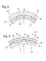
- FIG. 2 shows in detail that region in which the second friction element carrier 40 with its external toothing 52 is in mesh with the internal toothing 50 of the friction elements 46 of the second group of friction elements 48.
- each of the toothings 50, 52 has a A plurality of circumferentially successive teeth 66 and 68, which are preferably in engagement with each other so that only a slight rotational movement clearance between the second Reibelementenarme 40 and the friction elements 46 is made.
- a so-called root circle can be defined in association with each of the teeth 50, 52 and the teeth 66, 68 thereof.
- the root circle of the internal teeth 50 of the friction elements 46 is defined by a circle with the radius r a , the radial starting point or the radially outer End of the teeth 66 defined.
- the radial extension length of the teeth 66 of the internal teeth 50 can thus be measured starting from this root circle with the radius r a .
- the root circle of the external toothing 52 with the teeth 68 has a radius r i and thus defines the radially inner end or the radially inner starting point of the teeth 68 of the outer toothing 52.
- the two foot circles define a fictitious or maximally possible passage area between the second Friction element carrier 40 and the friction elements 46 of the second group of friction elements 48, said passage area is defined as the annular surface between the two foot circles with the diameters r a and r i .
- the actually obtainable passage area for the passage of fluid is actually smaller than this between the twotician Vietnameseen with the radii r a and r i defined annular surface, since portions of this maximum possible passage area are occupied by the teeth 66 and 68 of the teeth 50 and 52.
- FIG. 3 shows the region of the coupling of the friction elements 32 of the first group 34 of friction elements with the first friction element carrier 30, that is to say the axially extending section 28 of the motor-side housing shell 14.
- the internal toothing 36 of the first friction element carrier 30 has a plurality of circumferentially successive teeth 72 which mesh with teeth 74 of the external teeth 38 of the friction elements 32 in such a meshing engagement stand that there is substantially no circumferential movement clearance, while still allowing axial relative movement.
- respective foot circles for the teeth 72 and 74 can be defined in association with the toothings 36 and 38, the root circle of the internal toothing 36 of the first friction element carrier 30 being a circle with the radial r a 'and the root circle of the external toothing 38 of FIG Friction elements 32 is defined by a circle of radius r i '.
- a ring-like surface area is defined between the two foot circles with these radii r a 'and r i ', which can be defined as the theoretical or maximum possible fluid passage area.
- the actually existing area for a fluid passage 76 in this area is smaller due to the respective teeth 72, 74 extending radially into this annular area.
- an area ratio V 1 between this existing area of the fluid passage 76 and the maximum possible passage area in the range of 0.3 ⁇ V 1 ⁇ 0.7 has proven to be particularly advantageous. It is apparent that this can be obtained in a shifted compared to the previously discussed with reference to FIG. 2 ratio V 2 in a slightly higher area ratio V 1, inter alia, that the teeth 72 of the external teeth 36 of the first Reibelementenrlys with radial Indentations 78 are provided, which thus generate an increase in the area of the fluid passage 76. As in the case of the region which can be recognized in FIG.
- the area ratio V 1 or V 2 to be provided is also achieved, inter alia, by the fact that the teeth 36, 38 and 50, 52, which mesh with one another in mesh, have different numbers of teeth.
- the respective Reibelementenrities 30 and 40 has a greater number of teeth, as each having to be coupled thereto friction elements 32 and 46, for example, twice the number of teeth.
Landscapes
- Engineering & Computer Science (AREA)
- General Engineering & Computer Science (AREA)
- Mechanical Engineering (AREA)
- Mechanical Operated Clutches (AREA)
- Hydraulic Clutches, Magnetic Clutches, Fluid Clutches, And Fluid Joints (AREA)
- Body Structure For Vehicles (AREA)
- Vehicle Body Suspensions (AREA)
Applications Claiming Priority (1)
| Application Number | Priority Date | Filing Date | Title |
|---|---|---|---|
| DE102006047296A DE102006047296A1 (de) | 2006-10-06 | 2006-10-06 | Kupplungsanordnung für ein Fahrzeug |
Publications (3)
| Publication Number | Publication Date |
|---|---|
| EP1908976A2 true EP1908976A2 (fr) | 2008-04-09 |
| EP1908976A3 EP1908976A3 (fr) | 2010-04-28 |
| EP1908976B1 EP1908976B1 (fr) | 2011-05-04 |
Family
ID=38884687
Family Applications (1)
| Application Number | Title | Priority Date | Filing Date |
|---|---|---|---|
| EP07018768A Not-in-force EP1908976B1 (fr) | 2006-10-06 | 2007-09-25 | Dispositif de couplage pour un véhicule |
Country Status (5)
| Country | Link |
|---|---|
| US (1) | US20080128237A1 (fr) |
| EP (1) | EP1908976B1 (fr) |
| JP (1) | JP2008095952A (fr) |
| AT (1) | ATE508291T1 (fr) |
| DE (2) | DE102006047296A1 (fr) |
Families Citing this family (4)
| Publication number | Priority date | Publication date | Assignee | Title |
|---|---|---|---|---|
| DE102013000650A1 (de) * | 2013-01-16 | 2014-07-17 | Volkswagen Aktiengesellschaft | Kupplungsvorrichtung, insbesondere Mehrfachkupplungsvorrichtung |
| JP6584985B2 (ja) * | 2016-03-18 | 2019-10-02 | 本田技研工業株式会社 | 湿式多板クラッチ |
| DE102017206053A1 (de) * | 2017-04-10 | 2018-10-11 | Zf Friedrichshafen Ag | Schaltelement für ein Automatikgetriebe |
| FR3081952B1 (fr) * | 2018-06-01 | 2020-06-26 | Valeo Embrayages | Porte-disque assemble et mecanisme d'embrayage humide comprenant ce porte-disque assemble |
Family Cites Families (9)
| Publication number | Priority date | Publication date | Assignee | Title |
|---|---|---|---|---|
| US304479A (en) * | 1884-09-02 | weston | ||
| JP2884483B2 (ja) * | 1995-08-29 | 1999-04-19 | 本田技研工業株式会社 | 湿式多板クラッチの潤滑構造 |
| DE19831503A1 (de) * | 1998-07-14 | 2000-01-20 | Zahnradfabrik Friedrichshafen | Synchronisiereinrichtung |
| JP2002098171A (ja) * | 2000-09-21 | 2002-04-05 | Jatco Transtechnology Ltd | 自動変速機の発進クラッチ潤滑制御装置 |
| DE10234822A1 (de) * | 2002-07-31 | 2004-02-19 | Zf Sachs Ag | Kupplungsanordnung |
| DE50301795D1 (de) * | 2002-11-19 | 2006-01-05 | Volkswagen Ag | Kfz-Getriebe mit Lamellenkupplung |
| JP2005024014A (ja) * | 2003-07-03 | 2005-01-27 | Nsk Warner Kk | 湿式多板クラッチ |
| US7810622B2 (en) * | 2004-03-22 | 2010-10-12 | Gm Global Technology Operations, Inc. | Transmission clutches |
| DE502004002172D1 (de) * | 2004-04-10 | 2007-01-11 | Borgwarner Inc | Kupplungseinrichtung, insbesondere Anfahrkupplungseinrichtung |
-
2006
- 2006-10-06 DE DE102006047296A patent/DE102006047296A1/de not_active Withdrawn
-
2007
- 2007-08-21 JP JP2007214784A patent/JP2008095952A/ja active Pending
- 2007-09-25 DE DE502007007109T patent/DE502007007109D1/de active Active
- 2007-09-25 AT AT07018768T patent/ATE508291T1/de active
- 2007-09-25 EP EP07018768A patent/EP1908976B1/fr not_active Not-in-force
- 2007-10-04 US US11/906,838 patent/US20080128237A1/en not_active Abandoned
Also Published As
| Publication number | Publication date |
|---|---|
| EP1908976B1 (fr) | 2011-05-04 |
| US20080128237A1 (en) | 2008-06-05 |
| DE102006047296A1 (de) | 2008-04-10 |
| DE502007007109D1 (de) | 2011-06-16 |
| ATE508291T1 (de) | 2011-05-15 |
| JP2008095952A (ja) | 2008-04-24 |
| EP1908976A3 (fr) | 2010-04-28 |
Similar Documents
| Publication | Publication Date | Title |
|---|---|---|
| EP1522753B1 (fr) | Embrayage double hydraulique | |
| DE102009002481B4 (de) | Antriebssystem mit Drehmomentübertragungsanordnung und hydrodynamische Kopplungsanordnung | |
| EP1664567B1 (fr) | Dispositif d'embrayage, en particulier embrayage a disques pour une boite de vitesses a embrayage double | |
| DE102011120776A1 (de) | Drehmomentwandler mit verriegelungskupplung | |
| DE69716183T2 (de) | Kupplungsreibbelag mit gitternetzförmigen Nuten | |
| DE102009050998B4 (de) | Doppelkupplung für ein automatisches oder automatisiertes Doppelkupplungsgetriebe | |
| EP1751444A1 (fr) | Dispositif de positionnement axial d'un systeme d'embrayage | |
| EP1422430A1 (fr) | Transmission de véhicule avec embrayage à multi-disques | |
| DE102007022422A1 (de) | Doppelkupplungsanordnung mit Kolbenführungselement | |
| DE102013012815A1 (de) | Doppelkupplungseinrichtung und Verfahren zur Montage einer Doppelkupplungseinrichtung | |
| DE102014220897A1 (de) | Kopplungsanordnung mit einer Schwingungsreduzierungseinrichtung und mit einer Kupplungseinrichtung | |
| DE112013000878T5 (de) | Dynamische Dämpfungsvorrichtung und Überbrückungsvorrichtung für eine Kraftübertragungsvorrichtung des Fluidtyps | |
| DE102014221573A1 (de) | Mehrfachkupplung, insbesondere Doppelkupplung, Kupplungsdruckraum sowie Pendelmassenträger-Turbine-Kopplung | |
| DE102016116993A1 (de) | Getriebe mit fluidverteilungs-kupplungsnabe | |
| DE102010034128A1 (de) | Parallele Doppelkupplungseinrichtung | |
| DE102011009419A1 (de) | Mehrfachkupplungseinrichtung und Antriebsstrang mit einer solchen Mehrfachkupplungseinrichtung | |
| DE102007043897A1 (de) | Aufbau einer Vorrichtung zur Drehmomentübertragung beim Starten eines Motors mit Rollengesperre | |
| WO2007048505A1 (fr) | Convertisseur hydrodynamique de couple de rotation dote d'un accouplement de pontage | |
| DE102010044379A1 (de) | Kupplung | |
| DE112015000773B4 (de) | Kupplungsvorrichtung mit einem Kolben, der gegen Reibscheiben drückt | |
| EP1908976B1 (fr) | Dispositif de couplage pour un véhicule | |
| DE112011102767B4 (de) | Drehmomentwandler | |
| DE112011102766B4 (de) | Drehmomentwandler | |
| WO2019206358A1 (fr) | Ensemble d'embrayage comprenant un composant porteur réalisé sous la forme d'une pièce en tôle et relié à un support de rotor ainsi que chaîne cinématique | |
| DE102007045588A1 (de) | Drehmomentübertragungseinrichtung |
Legal Events
| Date | Code | Title | Description |
|---|---|---|---|
| PUAI | Public reference made under article 153(3) epc to a published international application that has entered the european phase |
Free format text: ORIGINAL CODE: 0009012 |
|
| AK | Designated contracting states |
Kind code of ref document: A2 Designated state(s): AT BE BG CH CY CZ DE DK EE ES FI FR GB GR HU IE IS IT LI LT LU LV MC MT NL PL PT RO SE SI SK TR |
|
| AX | Request for extension of the european patent |
Extension state: AL BA HR MK RS |
|
| PUAL | Search report despatched |
Free format text: ORIGINAL CODE: 0009013 |
|
| AK | Designated contracting states |
Kind code of ref document: A3 Designated state(s): AT BE BG CH CY CZ DE DK EE ES FI FR GB GR HU IE IS IT LI LT LU LV MC MT NL PL PT RO SE SI SK TR |
|
| AX | Request for extension of the european patent |
Extension state: AL BA HR MK RS |
|
| 17P | Request for examination filed |
Effective date: 20101022 |
|
| GRAP | Despatch of communication of intention to grant a patent |
Free format text: ORIGINAL CODE: EPIDOSNIGR1 |
|
| RIC1 | Information provided on ipc code assigned before grant |
Ipc: F16D 25/0638 20060101ALI20101111BHEP Ipc: F16D 13/68 20060101AFI20101111BHEP Ipc: F16D 25/12 20060101ALI20101111BHEP |
|
| AKX | Designation fees paid |
Designated state(s): AT BE BG CH CY CZ DE DK EE ES FI FR GB GR HU IE IS IT LI LT LU LV MC MT NL PL PT RO SE SI SK TR |
|
| GRAS | Grant fee paid |
Free format text: ORIGINAL CODE: EPIDOSNIGR3 |
|
| GRAA | (expected) grant |
Free format text: ORIGINAL CODE: 0009210 |
|
| AK | Designated contracting states |
Kind code of ref document: B1 Designated state(s): AT BE BG CH CY CZ DE DK EE ES FI FR GB GR HU IE IS IT LI LT LU LV MC MT NL PL PT RO SE SI SK TR |
|
| REG | Reference to a national code |
Ref country code: GB Ref legal event code: FG4D Free format text: NOT ENGLISH |
|
| REG | Reference to a national code |
Ref country code: CH Ref legal event code: EP |
|
| REG | Reference to a national code |
Ref country code: IE Ref legal event code: FG4D Free format text: LANGUAGE OF EP DOCUMENT: GERMAN |
|
| REF | Corresponds to: |
Ref document number: 502007007109 Country of ref document: DE Date of ref document: 20110616 Kind code of ref document: P |
|
| REG | Reference to a national code |
Ref country code: DE Ref legal event code: R096 Ref document number: 502007007109 Country of ref document: DE Effective date: 20110616 |
|
| REG | Reference to a national code |
Ref country code: NL Ref legal event code: VDEP Effective date: 20110504 |
|
| PG25 | Lapsed in a contracting state [announced via postgrant information from national office to epo] |
Ref country code: SE Free format text: LAPSE BECAUSE OF FAILURE TO SUBMIT A TRANSLATION OF THE DESCRIPTION OR TO PAY THE FEE WITHIN THE PRESCRIBED TIME-LIMIT Effective date: 20110504 Ref country code: PT Free format text: LAPSE BECAUSE OF FAILURE TO SUBMIT A TRANSLATION OF THE DESCRIPTION OR TO PAY THE FEE WITHIN THE PRESCRIBED TIME-LIMIT Effective date: 20110905 Ref country code: LT Free format text: LAPSE BECAUSE OF FAILURE TO SUBMIT A TRANSLATION OF THE DESCRIPTION OR TO PAY THE FEE WITHIN THE PRESCRIBED TIME-LIMIT Effective date: 20110504 |
|
| PG25 | Lapsed in a contracting state [announced via postgrant information from national office to epo] |
Ref country code: FI Free format text: LAPSE BECAUSE OF FAILURE TO SUBMIT A TRANSLATION OF THE DESCRIPTION OR TO PAY THE FEE WITHIN THE PRESCRIBED TIME-LIMIT Effective date: 20110504 Ref country code: LV Free format text: LAPSE BECAUSE OF FAILURE TO SUBMIT A TRANSLATION OF THE DESCRIPTION OR TO PAY THE FEE WITHIN THE PRESCRIBED TIME-LIMIT Effective date: 20110504 Ref country code: CY Free format text: LAPSE BECAUSE OF FAILURE TO SUBMIT A TRANSLATION OF THE DESCRIPTION OR TO PAY THE FEE WITHIN THE PRESCRIBED TIME-LIMIT Effective date: 20110504 Ref country code: GR Free format text: LAPSE BECAUSE OF FAILURE TO SUBMIT A TRANSLATION OF THE DESCRIPTION OR TO PAY THE FEE WITHIN THE PRESCRIBED TIME-LIMIT Effective date: 20110805 Ref country code: IS Free format text: LAPSE BECAUSE OF FAILURE TO SUBMIT A TRANSLATION OF THE DESCRIPTION OR TO PAY THE FEE WITHIN THE PRESCRIBED TIME-LIMIT Effective date: 20110904 Ref country code: ES Free format text: LAPSE BECAUSE OF FAILURE TO SUBMIT A TRANSLATION OF THE DESCRIPTION OR TO PAY THE FEE WITHIN THE PRESCRIBED TIME-LIMIT Effective date: 20110815 Ref country code: SI Free format text: LAPSE BECAUSE OF FAILURE TO SUBMIT A TRANSLATION OF THE DESCRIPTION OR TO PAY THE FEE WITHIN THE PRESCRIBED TIME-LIMIT Effective date: 20110504 |
|
| REG | Reference to a national code |
Ref country code: IE Ref legal event code: FD4D |
|
| PG25 | Lapsed in a contracting state [announced via postgrant information from national office to epo] |
Ref country code: NL Free format text: LAPSE BECAUSE OF FAILURE TO SUBMIT A TRANSLATION OF THE DESCRIPTION OR TO PAY THE FEE WITHIN THE PRESCRIBED TIME-LIMIT Effective date: 20110504 |
|
| PG25 | Lapsed in a contracting state [announced via postgrant information from national office to epo] |
Ref country code: CZ Free format text: LAPSE BECAUSE OF FAILURE TO SUBMIT A TRANSLATION OF THE DESCRIPTION OR TO PAY THE FEE WITHIN THE PRESCRIBED TIME-LIMIT Effective date: 20110504 Ref country code: EE Free format text: LAPSE BECAUSE OF FAILURE TO SUBMIT A TRANSLATION OF THE DESCRIPTION OR TO PAY THE FEE WITHIN THE PRESCRIBED TIME-LIMIT Effective date: 20110504 Ref country code: IE Free format text: LAPSE BECAUSE OF FAILURE TO SUBMIT A TRANSLATION OF THE DESCRIPTION OR TO PAY THE FEE WITHIN THE PRESCRIBED TIME-LIMIT Effective date: 20110504 |
|
| PG25 | Lapsed in a contracting state [announced via postgrant information from national office to epo] |
Ref country code: RO Free format text: LAPSE BECAUSE OF FAILURE TO SUBMIT A TRANSLATION OF THE DESCRIPTION OR TO PAY THE FEE WITHIN THE PRESCRIBED TIME-LIMIT Effective date: 20110504 Ref country code: SK Free format text: LAPSE BECAUSE OF FAILURE TO SUBMIT A TRANSLATION OF THE DESCRIPTION OR TO PAY THE FEE WITHIN THE PRESCRIBED TIME-LIMIT Effective date: 20110504 Ref country code: PL Free format text: LAPSE BECAUSE OF FAILURE TO SUBMIT A TRANSLATION OF THE DESCRIPTION OR TO PAY THE FEE WITHIN THE PRESCRIBED TIME-LIMIT Effective date: 20110504 Ref country code: DK Free format text: LAPSE BECAUSE OF FAILURE TO SUBMIT A TRANSLATION OF THE DESCRIPTION OR TO PAY THE FEE WITHIN THE PRESCRIBED TIME-LIMIT Effective date: 20110504 |
|
| PLBE | No opposition filed within time limit |
Free format text: ORIGINAL CODE: 0009261 |
|
| STAA | Information on the status of an ep patent application or granted ep patent |
Free format text: STATUS: NO OPPOSITION FILED WITHIN TIME LIMIT |
|
| BERE | Be: lapsed |
Owner name: ZF FRIEDRICHSHAFEN A.G. Effective date: 20110930 |
|
| 26N | No opposition filed |
Effective date: 20120207 |
|
| PG25 | Lapsed in a contracting state [announced via postgrant information from national office to epo] |
Ref country code: MC Free format text: LAPSE BECAUSE OF NON-PAYMENT OF DUE FEES Effective date: 20110930 |
|
| REG | Reference to a national code |
Ref country code: CH Ref legal event code: PL |
|
| GBPC | Gb: european patent ceased through non-payment of renewal fee |
Effective date: 20110925 |
|
| PG25 | Lapsed in a contracting state [announced via postgrant information from national office to epo] |
Ref country code: IT Free format text: LAPSE BECAUSE OF FAILURE TO SUBMIT A TRANSLATION OF THE DESCRIPTION OR TO PAY THE FEE WITHIN THE PRESCRIBED TIME-LIMIT Effective date: 20110504 |
|
| REG | Reference to a national code |
Ref country code: DE Ref legal event code: R097 Ref document number: 502007007109 Country of ref document: DE Effective date: 20120207 |
|
| REG | Reference to a national code |
Ref country code: FR Ref legal event code: ST Effective date: 20120531 |
|
| PG25 | Lapsed in a contracting state [announced via postgrant information from national office to epo] |
Ref country code: BE Free format text: LAPSE BECAUSE OF NON-PAYMENT OF DUE FEES Effective date: 20110930 |
|
| PG25 | Lapsed in a contracting state [announced via postgrant information from national office to epo] |
Ref country code: LI Free format text: LAPSE BECAUSE OF NON-PAYMENT OF DUE FEES Effective date: 20110930 Ref country code: CH Free format text: LAPSE BECAUSE OF NON-PAYMENT OF DUE FEES Effective date: 20110930 |
|
| PG25 | Lapsed in a contracting state [announced via postgrant information from national office to epo] |
Ref country code: FR Free format text: LAPSE BECAUSE OF NON-PAYMENT OF DUE FEES Effective date: 20110930 Ref country code: GB Free format text: LAPSE BECAUSE OF NON-PAYMENT OF DUE FEES Effective date: 20110925 |
|
| PG25 | Lapsed in a contracting state [announced via postgrant information from national office to epo] |
Ref country code: MT Free format text: LAPSE BECAUSE OF FAILURE TO SUBMIT A TRANSLATION OF THE DESCRIPTION OR TO PAY THE FEE WITHIN THE PRESCRIBED TIME-LIMIT Effective date: 20110504 |
|
| PG25 | Lapsed in a contracting state [announced via postgrant information from national office to epo] |
Ref country code: LU Free format text: LAPSE BECAUSE OF NON-PAYMENT OF DUE FEES Effective date: 20110925 |
|
| PG25 | Lapsed in a contracting state [announced via postgrant information from national office to epo] |
Ref country code: BG Free format text: LAPSE BECAUSE OF FAILURE TO SUBMIT A TRANSLATION OF THE DESCRIPTION OR TO PAY THE FEE WITHIN THE PRESCRIBED TIME-LIMIT Effective date: 20110804 |
|
| PG25 | Lapsed in a contracting state [announced via postgrant information from national office to epo] |
Ref country code: TR Free format text: LAPSE BECAUSE OF FAILURE TO SUBMIT A TRANSLATION OF THE DESCRIPTION OR TO PAY THE FEE WITHIN THE PRESCRIBED TIME-LIMIT Effective date: 20110504 |
|
| PG25 | Lapsed in a contracting state [announced via postgrant information from national office to epo] |
Ref country code: HU Free format text: LAPSE BECAUSE OF FAILURE TO SUBMIT A TRANSLATION OF THE DESCRIPTION OR TO PAY THE FEE WITHIN THE PRESCRIBED TIME-LIMIT Effective date: 20110504 |
|
| REG | Reference to a national code |
Ref country code: AT Ref legal event code: MM01 Ref document number: 508291 Country of ref document: AT Kind code of ref document: T Effective date: 20120925 |
|
| PG25 | Lapsed in a contracting state [announced via postgrant information from national office to epo] |
Ref country code: AT Free format text: LAPSE BECAUSE OF NON-PAYMENT OF DUE FEES Effective date: 20120925 |
|
| P01 | Opt-out of the competence of the unified patent court (upc) registered |
Effective date: 20230528 |
|
| PGFP | Annual fee paid to national office [announced via postgrant information from national office to epo] |
Ref country code: DE Payment date: 20230802 Year of fee payment: 17 |
|
| REG | Reference to a national code |
Ref country code: DE Ref legal event code: R119 Ref document number: 502007007109 Country of ref document: DE |
|
| PG25 | Lapsed in a contracting state [announced via postgrant information from national office to epo] |
Ref country code: DE Free format text: LAPSE BECAUSE OF NON-PAYMENT OF DUE FEES Effective date: 20250401 |