EP1908979B1 - Dispositif de transmission de puissance - Google Patents
Dispositif de transmission de puissance Download PDFInfo
- Publication number
- EP1908979B1 EP1908979B1 EP07117362A EP07117362A EP1908979B1 EP 1908979 B1 EP1908979 B1 EP 1908979B1 EP 07117362 A EP07117362 A EP 07117362A EP 07117362 A EP07117362 A EP 07117362A EP 1908979 B1 EP1908979 B1 EP 1908979B1
- Authority
- EP
- European Patent Office
- Prior art keywords
- cam
- main
- rotation plate
- pilot
- clutch
- Prior art date
- Legal status (The legal status is an assumption and is not a legal conclusion. Google has not performed a legal analysis and makes no representation as to the accuracy of the status listed.)
- Ceased
Links
- 230000007935 neutral effect Effects 0.000 claims description 19
- 230000005540 biological transmission Effects 0.000 claims 1
- 238000010586 diagram Methods 0.000 description 3
- 239000000314 lubricant Substances 0.000 description 2
- 244000182067 Fraxinus ornus Species 0.000 description 1
- 230000001133 acceleration Effects 0.000 description 1
- 238000013459 approach Methods 0.000 description 1
- 230000006835 compression Effects 0.000 description 1
- 238000007906 compression Methods 0.000 description 1
- 230000007423 decrease Effects 0.000 description 1
- 230000000694 effects Effects 0.000 description 1
- 230000005611 electricity Effects 0.000 description 1
- 239000000446 fuel Substances 0.000 description 1
Images


Classifications
-
- F—MECHANICAL ENGINEERING; LIGHTING; HEATING; WEAPONS; BLASTING
- F16—ENGINEERING ELEMENTS AND UNITS; GENERAL MEASURES FOR PRODUCING AND MAINTAINING EFFECTIVE FUNCTIONING OF MACHINES OR INSTALLATIONS; THERMAL INSULATION IN GENERAL
- F16D—COUPLINGS FOR TRANSMITTING ROTATION; CLUTCHES; BRAKES
- F16D27/00—Magnetically- or electrically- actuated clutches; Control or electric circuits therefor
- F16D27/10—Magnetically- or electrically- actuated clutches; Control or electric circuits therefor with an electromagnet not rotating with a clutching member, i.e. without collecting rings
- F16D27/108—Magnetically- or electrically- actuated clutches; Control or electric circuits therefor with an electromagnet not rotating with a clutching member, i.e. without collecting rings with axially movable clutching members
- F16D27/112—Magnetically- or electrically- actuated clutches; Control or electric circuits therefor with an electromagnet not rotating with a clutching member, i.e. without collecting rings with axially movable clutching members with flat friction surfaces, e.g. discs
- F16D27/115—Magnetically- or electrically- actuated clutches; Control or electric circuits therefor with an electromagnet not rotating with a clutching member, i.e. without collecting rings with axially movable clutching members with flat friction surfaces, e.g. discs with more than two discs, e.g. multiple lamellae
-
- F—MECHANICAL ENGINEERING; LIGHTING; HEATING; WEAPONS; BLASTING
- F16—ENGINEERING ELEMENTS AND UNITS; GENERAL MEASURES FOR PRODUCING AND MAINTAINING EFFECTIVE FUNCTIONING OF MACHINES OR INSTALLATIONS; THERMAL INSULATION IN GENERAL
- F16D—COUPLINGS FOR TRANSMITTING ROTATION; CLUTCHES; BRAKES
- F16D27/00—Magnetically- or electrically- actuated clutches; Control or electric circuits therefor
- F16D27/004—Magnetically- or electrically- actuated clutches; Control or electric circuits therefor with permanent magnets combined with electromagnets
Definitions
- the present invention relates to a power transmitting device.
- the power transmitting device disclosed in Japanese Laid-Open Patent Publication No. 2004-108575 is provided with a cylindrical rotating member which rotates when a driving force is inputted and a rotary shaft member which is placed within the cylindrical rotating member so as to be freely rotatable and coaxial with the cylindrical rotating member.
- a clutch mechanism provided between the cylindrical rotating member and the rotary shaft member permits torque to be transmitted between the cylindrical rotating member and the rotary shaft member.
- This power transmitting device is provided with a cam mechanism as shown in Fig. 7 .
- the cam mechanism is provided with spherical bodies 83 and a stopper body 84 between a main cam 81 and a pilot cam 82.
- the main cam 81 and the stopper body 84 are urged by a torsion spring 85 to be rotated so that a protrusion 86 of the main cam 81 and an engaging protrusion 87 of the stopper body 84 engage with each other.
- the pilot cam 82 receives the rotation of the engine provided in the front portion of the vehicle through an electromagnetic clutch and a pilot clutch.
- the rotational torque generated in the pilot cam 82 exceeds the urging force of the torsion spring 85
- the pilot cam 82 and the main cam 81 rotate relative to each other.
- the spherical bodies 83 between the two cams 81 and 82 move the main cam 81 in the axial direction.
- the driving force is transmitted from the engine to the rear wheels through a main friction clutch (not shown).
- clutch plates of the main friction clutch sometimes rub against each other even when the main friction clutch is not engaged.
- a great number of main frictional clutches are a wet type clutch, in which lubricant exists between the respective clutch plates is formed. Therefore, in the case where the number of rotations of the front wheels becomes greater than that of the rear wheels, for example, when a spare tire for emergencies is used or at the time of quick acceleration, a problem arises where part of the torque becomes drag torque due to the viscosity of the lubricant intervened between the clutch plates, and is transmitted to the driven side.
- Another power transmitting device is known from GB-A-2308426 .
- An objective of the present invention is to provide a power transmitting device where a drag torque generated as a result of the rotational difference between the front and rear wheels is reduced.
- the power transmitting device 10 transmits driving force between the front and rear wheels of a four-wheel drive vehicle.
- the power transmitting device 10 is used in a front wheel drive-based four-wheel drive vehicle, in which driving force is always transmitted to the front wheels from the drive source, such as an engine or an electric motor, and the driving force is also distributed to the rear wheels depending on the running state of the vehicle.
- the driving force from the drive source mounted in the front of the vehicle is transmitted to the axle shaft of the front wheels via a transfer case so that the front wheels are driven.
- the transfer case is also linked to the power transmitting device 10 via a drive shaft.
- the power transmitting device 10 is linked to the axle shaft of the rear wheels via a drive pinion shaft and a differential gear.
- This power transmitting device 10 links the drive shaft and the drive pinion shaft to each other so that torque can be transmitted therebetween.
- the driving force of the engine is transmitted to the axle shaft of the rear wheels via the power transmitting device 10, the drive pinion shaft, and the differential gear, so that the rear wheels are driven.
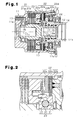
- the power transmitting device 10 is provided with a front housing member 11, which is a first rotating member, and an inner shaft 12, which is a second rotating member.
- the front housing member 11 is formed in cylindrical form having a bottom.
- the inner shaft 12 is formed into a hollow shaft form and placed so as to be freely rotatable within the front housing member 11 and coaxial with the front housing member 11.
- the front housing member 11 is linked to a propeller shaft (not shown) by threading a bolt (not shown) into the threaded hole 13 so as to be rotated together with the propeller shaft by the driving force generated by the engine (not shown), which is the drive source.
- a linking portion in a shaft form may be created by forming a spline in the outer periphery of the front housing member 11 so that the front housing member 11 and the propeller shaft are linked through this linking portion.
- annular rear housing member 14 is engaged with an open end 11b of the front housing member 11.
- An end portion of the inner shaft 12 is inserted into the center hole 14a of the rear housing member 14.
- the inner shaft 12 is supported so as to be freely rotatable by the bearing 15 within the center hole 14a and the ball bearing 16 within the front housing member 11.
- a linking portion (spline engaging portion) 17 to the rear differential (not shown) is formed on the inner circumferential surface of the inner shaft 12 in the vicinity of the rear housing member 14 (right side of Fig. 1 ).
- a pilot clutch 22 is provided within the front housing member 11 in a location at a distance from the main clutch 21 in the axial direction, that is to say, in the vicinity of the rear housing member 14.
- a cam mechanism 23 is provided within the front housing member 11 between the main clutch 21 and the pilot clutch 22.
- a multi-plate friction clutch is used as the main clutch 21.
- the main clutch 21 is configured by alternately placing a number of outer clutch plates 21a and inner clutch plates 21b which are moveable in the axial direction.
- the respective outer clutch plates 21a are moveable in the axial direction by means of spline engagement with the inner circumferential surface of the front housing member 11 and rotatable together with the front housing member 11.
- the respective inner clutch plates 21b are moveable in the axial direction by means of spline engagement with the outer circumferential surface of the inner shaft 12 and rotatable together with the inner shaft 12.
- the respective outer clutch plates 21a and the respective inner clutch plates 21b are pressed toward the front housing member 11 along the axial direction so that these engage with each other through friction.
- the front housing member 11 and the inner shaft 12 are linked so that torque can be transmitted therebetween.
- the cam mechanism 23 is provided with a pilot cam 31, which is a first cam member, a main cam 32, which is a second cam member, and balls 33, which are located between the two cams 31 and 32.
- the pilot cam 31 is supported so as to be freely rotatable around an axis 12a relative to the inner shaft 12.
- the main cam 32 is engaged with the outer circumferential surface of the inner shaft 12 by menas of spline. As a result, the main cam 32 is moveable along an axis 11c and rotatable together with the inner shaft 12 around the axis 11c.
- the pilot cam 31 and the main cam 32 are formed in disc form.
- the pilot cam 31 is placed in the proximity to the rear housing member 14, and the main cam 32 is placed in the proximity to the main clutch 21.
- the outer circumferential surface of the pilot cam 31 is engaged with the inner circumferential of the below described inner clutch plate 22b by means of spline
- the main cam 32 is engaged with the outer circumferential surface of the inner shaft 12 by means of spline.
- a number of cam grooves 34 and 35 are formed on the two facing surfaces of the pilot cam 31 and the main cam 32 so as to face each other.
- the balls 33 are placed between the facing cam grooves 34 and 35 and held by the pilot cam 31 and the main cam 32.
- the main cam 32 moves along the axial direction through the engagement of the cam grooves 34, 35 and the balls 33, so as to move away from the pilot cam 31.
- a multi-plate friction clutch is used as the pilot clutch 22 in the same manner as the main clutch 21.
- the pilot clutch 22 is formed by alternately placing a number of outer clutch plates 22a and inner clutch plates 22b which are moveable in the axial direction.
- the respective outer clutch plates 22a are engaged with the inner circumferential surface of the front housing member 11 by means of spline.
- the respective inner clutch plates 22b are engaged with the outer circumferential surface of the pilot cam 31 by means of spline.
- the respective inner clutch plates 22b are moveable in the axial direction and rotatable together with the pilot cam 31.
- the respective outer clutch plates 22a and the respective inner clutch plates 22b are pressed toward the rear housing member 14 along the axial direction so as to engage with each other through friction.
- the front housing member 11 and the pilot cam 31 are linked so that torque can be transmitted therebetween.
- the pilot cam 31 When the pilot clutch 22 is not operating, the pilot cam 31 is rotatably coupled to the main cam 32 and the inner shaft 12, while holding the balls 33 with the main cam 32. In this case, there is a rotational difference between the front housing member 11 and the pilot cam 31, which corresponds to a rotational difference between the front housing member 11 and the inner shaft 12.
- the pilot clutch 22 operates in such a manner that the front housing member 11 and the pilot cam 31 are linked so that torque can be transmitted therebetween, and thus, torque on the basis of the rotational difference between the front housing member 11 and the inner shaft 12 (pilot cam 31) is transmitted to the cam mechanism 23.
- the cam mechanism 23 moves the main cam 32 in the axial direction so that the main cam 32 comes close to the main clutch 21. That is to say, the cam mechanism 23 converts the torque on the basis of the rotational difference between the front housing member 11 and the inner shaft 12 into a pressing force in the axial direction, and presses the main clutch 21 through the main cam 32. This activates the main clutch 21, so that the front housing member 11 and the inner shaft 12 are linked so that torque can be transmitted therebetween.
- the pilot clutch 22 is an electromagnetic clutch having an electromagnet 22c as a drive source.
- An annular groove 22d having an opening on the same side of the opening of the front housing member 11 is created in the rear housing member 14.
- the electromagnet 22c is contained within this groove 22d.
- the rear housing member 14 has a cylindrical portion 14b.
- the cylindrical portion 14b has a hollow that is coaxial with the center hole 14a.
- the electromagnet 22c is supported by the ball bearing 24 which is provided in the cylindrical portion 14b so as to be rotatable relative to the rear housing member 14 and the front housing member 11.
- An annular armature 22e is provided within the front housing member 11.
- the armature 22e is placed so as to hold the outer clutch plate 22a and the inner clutch plate 22b with the rear housing member 14.
- the armature 22e is engaged with the front housing member 11 by means of spline so as to be slidable in the axial direction against the front housing member 11.
- the pilot clutch 22 the armature 22e is attracted by the electromagnetic force of the electromagnet 22c and approaches the rear housing member 14.
- the respective outer clutch plates 22a and the respective inner clutch plates 22b are held between the armature 22e and the rear housing member 14, and thus, the respective outer clutch plates 22a and the respective inner clutch plates 22b are engaged with each other through friction.
- the operation of the main clutch 21 is controlled through the operation control of the pilot clutch 22 by electricity supplied to the electromagnet 22c, that is to say, the control of the engaging force through friction, and thus, the driving force which is transmitted between the front housing member 11 and the inner shaft 12 is controlled.
- the main cam 32 is provided with a boss wall portion 41 into which the inner shaft 12 is inserted, a side wall portion 42 which extends from the outer circumferential portion of the boss wall portion 41 in the radial direction, and an outer circumferential wall portion 43 which is provided on the outer circumferential portion of the side wall portion 42 so as to face the boss wall portion 41.
- the main cam 32 is provided with a space created between the outer circumferential wall portion 43 and the boss wall portion 41. The space serves as an accommodating portion 44.
- Cam grooves 35 are formed on the boss wall portion 41 at an equal angular interval.
- Cam grooves 34 which face the cam groove 35 are formed on the pilot cam 31 (see Fig. 2 ).
- the balls 33 are held between the cam grooves 34 and 35 in a state as to make contact with the respective cam grooves 34 and 35.
- Each of the cam grooves 34 and 35 has an arcuate outer shape, and arranged at an equal interval on a circle the center of which is the rotation axes 11c, 12a.
- the depth of each of the cam grooves 34, 35 at the center is substantially equal to radius of the balls 33, and gradually decreases from the center to both ends.
- Six engaging projections 45a to 45f are aligned in the circumferential direction of the main cam 32 within the accommodating portion 44.
- the respective engaging projections 45a to 45f are in plate form and extend from the outer circumferential wall portion 43 toward the center of the main cam 32.
- a forward rotation plate 46 and a reverse rotation plate 47 are engaged with the accommodating portion 44 so as to be rotatable relative to the main cam 32.
- an annular lid member 48 is engaged with the accommodating portion 44.
- the forward rotation plate 46 is provided with an annular main body portion 51 and two forward rotation engaging pieces 52a and 52b which extend outward from the main body portion 51 the radial direction.
- the forward rotation plate 46 is provided with a cylindrical portion 53 which extends from the outer periphery of the main body portion 51 toward the main cam 32.
- the cylindrical portion 53 is placed in the proximity to the center of the main cam 32 relative to the respective engaging projections 45a to 45f.
- the reverse rotation plate 47 is provided with the annular main body portion 54 and four reverse rotation engaging pieces 55a to 55d which extend outward from the main body portion 54 in the radial direction.
- the respective forward rotation engaging pieces 52a and 52b as well as the respective reverse rotation engaging pieces 55a to 55d are placed between the respective engaging projections 45a to 45f of the main cam 32.
- the cylindrical portion 53 of the forward rotation plate 46, the side wall portion 42 and the outer circumferential wall portion 43 of the main cam 32, and the lid member 48 form spring accommodating chambers for accommodating coil springs 57a to 57f, which are urging members between the respective engaging projections 45a to 45f.
- the respective coil springs 57a to 57f are compression coil springs.
- the respective coil springs 57a to 57f urge the respective engaging pieces 52a, 52b and 55a to 55d and the respective engaging projections 45a to 45f in the circumferential direction in such a state as being placed in the respective spring accommodating chambers.
- the coil springs 57a and 57d which are first elastic members, for example, urge the main cam 32 and the forward rotation plate 46 in such a manner that they rotate in the direction opposite to each other.
- the respective engaging pieces 52a and 52b of the forward rotation plate 46 engage with the engaging projections 45b and 45e, which are first limiting portions of the main cam 32. Accordingly, the respective engaging projections 45b and 45e limit the rotations of the main cam 32 and the forward rotation plate 46 relative to each other.
- the coil springs 57b, 57c, 57e and 57f which are second elastic members, urge the main cam 32 and the reverse rotation plate 47 so that they rotate in the direction opposite to each other.
- the respective coil springs 57a to 57f are provided so as to make the direction of rotation of the forward rotation plate 46 and the direction of rotation of the reverse rotation plate 47 opposite to each other.
- the respective engaging pieces 55a, 55b, 55c and 55d of the reverse rotation plate 47 engage with the engaging projections 45b, 45c, 45e and 45f, which are the second limiting portions of the main cam 32. Accordingly, the respective engaging projections 45b, 45c, 45e and 45f limit the rotations of the main cam 32 and the reverse rotation plate 47 relative to each other.
- a snap ring 49 which is a limiting body, is fitted into the outer circumferential wall portion 43 of the main cam 32.
- the snap ring 49 is fitted in such a manner as to hold the forward rotation plate 46, the reverse rotation plate 47, and the lid member 48 with the side wall portion 42 of the main cam 32.
- the snap ring 49 limits the movement of the respective plates 46 and 47, the lid member 48 and the respective coil springs 57a to 57f in the axial direction relative to the main cam 32.
- the respective plates 46 and 47, the lid member 48, the respective coil springs 57a to 57f and the snap ring 49 move in the axial direction together with the main cam 32.
- the pilot cam 31 is provided with two engaging protrusions 58 which extend toward the main cam 32.
- Engaging recesses 61 and 62 which engage with the respective engaging protrusions 58, are created in the main body portion 51 of the forward rotation plate 46 and the main body portion 54 of the reverse rotation plate 47, respectively.
- a first inner walls of the engaging recesses 61 of the forward rotation plate 46 engage with the engaging protrusions 58 of the pilot cam 31 when the pilot cam 31 rotates forward (rotates in the counterclockwise direction of Fig. 5(A) ) starting from the position shown in Fig. 5(A) .
- a second inner walls of the forward rotation plate 46 engage with the engaging protrusions 58 of the pilot cam 31 when the pilot cam 31 rotates reversely (rotates in the clockwise direction of Fig. 5(A) ) by a predetermined angle starting from the above described state.
- First inner walls of the engaging recesses 62 of the reverse rotation plate 47 engage with the engaging protrusions 58 of the pilot cam 31 when the pilot cam 31 rotates reversely starting from the position shown in Fig. 5(B) .
- second inner walls of the reverse rotation plates 47 of the engaging recesses 62 engage with the engaging protrusions 58 of the pilot cam 31 when the pilot cam 31 rotates forward by a predetermined angle starting from the above described state.
- the forward rotation plate 46 and the reverse rotation plate 47 are urged by the respective coil springs 57a to 57f so as to rotate in the directions opposite to each other relative to the main cam 32. Accordingly, the coil springs 57a to 57f urge the forward rotation plate 46 and the reverse rotation plate 47 in such a manner that the engaging protrusions 58 of the pilot cam 31 do not engage with the engaging recesses 61, 62 of the plates 46, 47.
- the main cam 32 and the pilot cam 31 are held by the balls 33 between the two cam grooves 35 and 34, which face each other, in such a state as not to generate a transfer force in the axial direction (see Fig. 2 ).
- the positions of the main cam 32 and the pilot cam 31 at this time are described in the following as neutral positions.
- the engaging protrusions 58 of the pilot cam 31 engage with the engaging recesses 61 of the forward rotation plate 46 so that the forward rotation plate 46 rotates forward.
- the respective coil springs 57a and 57d between the respective engaging pieces 52a and 52b of the forward rotation plate 46 and the respective engaging projections 45a and 45d of the main cam 32 urge the forward rotation plate 46 in the direction opposite to the direction of rotation of the pilot cam 31, and urge the main cam 32 in the same direction as the direction of the rotation of the pilot cam 31.
- the respective coil springs 57a and 57d urge the cam mechanism 23 toward the neutral position.
- the respective engaging projections 45b and 45e of the main cam 32 engage with the respective engaging projections 45b and 45e of the main cam 32, the coil springs do not urge the cam mechanism more.
- the respective engaging projections 45b and 45e engage with the respective engaging pieces 52a and 52b of the forward rotation plate 46, and thus, limit the rotations of the main cam 32 and the pilot cam 31 relative to each other beyond the neutral position.
- the cam mechanism 23 is provided with two coil springs 57a and 57d for urging the forward rotation plate 46 and four coil springs 57b, 57c, 57e and 57f for urging the reverse rotation plate 47.
- the numbers of the coil springs for each plate 46 and 47 are different in order to differentiate the forces for urging the main cam 32 and the pilot cam 31 toward the neutral position. That is to say, by providing different numbers of coil springs, the urging force generated between the reverse rotation plate 47 and the main cam 32 is greater than the urging force generated between the forward rotation plate 46 and the main cam 32.
- the main cam 32 does not move unless rotational torque which is greater than the rotational torque applied to the forward rotation plate 46 is applied to the reverse rotation plate 47. That is to say, it is more difficult for the reverse rotation plate 47 to move the main cam 32 than for the forward rotation plate 46 to move the main cam 32. In other words, greater rotational torque becomes necessary to move the main cam 32 and the pilot cam 31 relative to each other.
- the power transmitting device is applied to a front wheel-drive based four-wheel drive vehicle.
- the present invention may be applied to a rear wheel drive-based four-wheel drive vehicle where the engine is mounted in the rear portion of the vehicle.
- the number of coil springs is changed in order to differentiate the urging force working between the main cam 32 and the forward rotation plate 46 and the urging working between the main cam 32 and the reverse rotation plate 47.
- at least one from among the number, the length and the thickness of the coil springs may be changed.
- the urging force is generated by the respective coil springs 57a to 57f between the main cam 32 and the respective plates 46 and 47.
- the urging force may be generated by torsion springs.
- the main cam 32 is moved in accordance with the relative angle between the pilot cam 31 and the main cam 32 so as to generate a pressing force in the main clutch 21 by using the balls 33 and the two cam grooves 34 and 35.
- an inclining surface which inclines in the circumferential direction may be provided on the contacting surfaces of the pilot cam 31 and the main cam 32, and the main cam 32 may be moved along the axis in accordance with the relative angle between the pilot cam 31 and the main cam 32.
- a cam mechanism is provided with a forward rotation plate 46 and a reverse rotation plate 47.
- the respective plates 46 and 47 are urged by the respective coil springs 57a to 57f in the directions opposite to each other.
- the forward rotation plate 46 rotates.
- a main cam 32 which is urged by the respective coil springs 57a and 57d toward the neutral position rotates together with the forward rotation plate 46 when the forward rotation plate 46 rotates.
- the reverse rotation plate 47 rotates.
- the main cam 32 which is urged by the respective coil springs 57b, 57c, 57e and 57f toward the neutral position rotates together with the reverse rotation plate 47 when the reverse rotation plate 47 rotates.
Landscapes
- Engineering & Computer Science (AREA)
- General Engineering & Computer Science (AREA)
- Physics & Mathematics (AREA)
- Electromagnetism (AREA)
- Mechanical Engineering (AREA)
- Mechanical Operated Clutches (AREA)
- Arrangement And Driving Of Transmission Devices (AREA)
Claims (3)
- Dispositif (10) de transmission de puissance pour transmettre une force d'entraînement entre des roues avant et des roues arrière, comprenant un premier élément rotatif (11) pour le raccordement aux roues avant, un deuxième élément rotatif (12) pour le raccordement aux roues arrière, un embrayage principal (21) pourvu entre les deux éléments rotatifs (11, 12) pour commander la transmission de la force d'entraînement entre les deux éléments rotatifs (11, 12); et un mécanisme à cames (23) pour appliquer une force de pression dans une direction axiale à l'embrayage principal (21), le mécanisme à cames (23) ayant un premier élément de came (31) et un deuxième élément de came (32), les premier et deuxième éléments de came (31, 32) étant en rotation l'un par rapport à l'autre en raison d'un couple de rotation transmis par le biais du premier ou du deuxième élément rotatif (11, 12), et ainsi, une force de pression dans la direction axiale étant appliquée à l'embrayage principal (21),
dans lequel le mécanisme à cames (23) a un premier élément élastique (57a, 57d) pour pousser le premier élément de came (31) vers une position neutre où aucune force de pression n'est appliquée à l'embrayage principal (21), et un deuxième élément élastique (57b, 57c, 57e, 57f) pour pousser le deuxième élément de came (32) vers la position neutre, et la direction dans laquelle le deuxième élément élastique (57b, 57c, 57e, 57f) pousse est opposée à la direction dans laquelle le premier élément élastique (57a, 57d) pousse, caractérisé par le fait de
comprendre en plus une première plaque de rotation (46) et une deuxième plaque de rotation (47), où
le premier élément élastique (57a, 57d) pousse le deuxième élément de came (32) et la première plaque de rotation (46) de sorte à ce qu'ils se mettent en rotation dans la direction opposée l'un par rapport à l'autre, et
le deuxième élément élastique (57b, 57c, 57e, 57f) pousse le deuxième élément de came (32) et la deuxième plaque de rotation (47) de sorte à ce qu'ils se mettent en rotation dans la direction opposée l'un par rapport à l'autre. - Dispositif (10) de transmission de puissance selon la revendication 1, étant en plus caractérisé par:une première partie de limitation (45b, 45e) pour limiter la rotation du premier élément de came (31) par rapport au deuxième élément de came (32) au-delà de la position neutre; etune deuxième partie de limitation (45b, 45c, 45e, 45f) pour limiter la rotation du deuxième élément de came (32) par rapport au premier élément de came (31) au-delà de la position neutre.
- Dispositif (10) de transmission de puissance selon la revendication 1 ou 2, étant caractérisé en ce que la force de poussée créée par le premier élément élastique (57a, 57d) et la force de poussée créée par le deuxième élément élastique (57b, 57c, 57e, 57f) sont différentes.
Applications Claiming Priority (1)
| Application Number | Priority Date | Filing Date | Title |
|---|---|---|---|
| JP2006269700A JP4905036B2 (ja) | 2006-09-29 | 2006-09-29 | 駆動力伝達装置 |
Publications (2)
| Publication Number | Publication Date |
|---|---|
| EP1908979A1 EP1908979A1 (fr) | 2008-04-09 |
| EP1908979B1 true EP1908979B1 (fr) | 2009-04-29 |
Family
ID=38724523
Family Applications (1)
| Application Number | Title | Priority Date | Filing Date |
|---|---|---|---|
| EP07117362A Ceased EP1908979B1 (fr) | 2006-09-29 | 2007-09-27 | Dispositif de transmission de puissance |
Country Status (4)
| Country | Link |
|---|---|
| US (1) | US8151958B2 (fr) |
| EP (1) | EP1908979B1 (fr) |
| JP (1) | JP4905036B2 (fr) |
| DE (1) | DE602007001010D1 (fr) |
Families Citing this family (4)
| Publication number | Priority date | Publication date | Assignee | Title |
|---|---|---|---|---|
| CN102448756B (zh) * | 2009-05-27 | 2014-12-10 | 丰田自动车株式会社 | 混合动力车辆的控制装置 |
| CN102459941B (zh) * | 2009-06-23 | 2015-05-13 | 麦格纳动力系有限公司 | 球坡道离合器 |
| JP5672976B2 (ja) * | 2010-11-01 | 2015-02-18 | 株式会社ジェイテクト | 電磁クラッチ |
| JP2015206423A (ja) * | 2014-04-22 | 2015-11-19 | トヨタ自動車株式会社 | カム機構 |
Family Cites Families (7)
| Publication number | Priority date | Publication date | Assignee | Title |
|---|---|---|---|---|
| US5642612A (en) | 1995-12-19 | 1997-07-01 | Hughes; Ceiriog | Replaceable tip cable handler |
| JP3131164B2 (ja) * | 1995-12-21 | 2001-01-31 | ジー・ケー・エヌ・ヴィスコドライヴ・ゲゼルシャフト・ミット・ベシュレンクテル・ハフツング | 少なくとも1つのビスカス継手と摩擦継手とを有する継手ユニット |
| JP2001330060A (ja) * | 2000-05-22 | 2001-11-30 | Tochigi Fuji Ind Co Ltd | カップリング及びデファレンシャル装置 |
| DE60301837T2 (de) * | 2002-08-30 | 2006-06-29 | Toyoda Koki K.K., Kariya | Elektromagnetische Kupplung |
| JP4200853B2 (ja) | 2002-08-30 | 2008-12-24 | 株式会社ジェイテクト | 駆動力伝達装置及びそのアンバランス確認方法 |
| US6935475B2 (en) | 2003-03-28 | 2005-08-30 | Borgwarner, Inc. | Electromagnetic clutch having ball ramp actuator and torsion spring |
| JP4363999B2 (ja) | 2004-02-03 | 2009-11-11 | 本田技研工業株式会社 | クラッチ装置 |
-
2006
- 2006-09-29 JP JP2006269700A patent/JP4905036B2/ja not_active Expired - Fee Related
-
2007
- 2007-09-24 US US11/860,085 patent/US8151958B2/en not_active Expired - Fee Related
- 2007-09-27 EP EP07117362A patent/EP1908979B1/fr not_active Ceased
- 2007-09-27 DE DE602007001010T patent/DE602007001010D1/de active Active
Also Published As
| Publication number | Publication date |
|---|---|
| US20080078622A1 (en) | 2008-04-03 |
| JP4905036B2 (ja) | 2012-03-28 |
| EP1908979A1 (fr) | 2008-04-09 |
| DE602007001010D1 (de) | 2009-06-10 |
| US8151958B2 (en) | 2012-04-10 |
| JP2008089047A (ja) | 2008-04-17 |
Similar Documents
| Publication | Publication Date | Title |
|---|---|---|
| CN110454513B (zh) | 动力传递装置 | |
| WO2011118630A1 (fr) | Dispositif de freinage avec mécanisme de stationnement motorisé | |
| WO2021210195A1 (fr) | Dispositif de transmission d'énergie | |
| WO2021210197A1 (fr) | Dispositif de transmission de puissance | |
| EP1908979B1 (fr) | Dispositif de transmission de puissance | |
| WO2022030349A1 (fr) | Dispositif de transmission de puissance | |
| JP5891966B2 (ja) | 駆動力伝達制御装置及び四輪駆動車 | |
| JP2006258296A (ja) | 前輪駆動トランスアクスル・ユニット用のトルク・カップリング装置 | |
| CN113586697B (zh) | 扭矩管理器 | |
| JP2005344778A (ja) | 駆動力伝達装置 | |
| EP1350657B1 (fr) | Dispositif de commutation de puissance entre deux et quatre roues motrices | |
| EP1760348B1 (fr) | Appareil de transfert de force d'entrainement | |
| JP2013130286A (ja) | 動力伝達装置 | |
| JP5504900B2 (ja) | カム機構及び電磁クラッチ | |
| JP2013108613A (ja) | クラッチ及び四輪駆動車 | |
| JP6040572B2 (ja) | 駆動力伝達制御装置 | |
| JP2007333133A (ja) | デファレンシャル装置 | |
| JP2004187476A (ja) | 電磁式アクチュエータ及びこれを用いたデファレンシャル装置 | |
| JP5753003B2 (ja) | クラッチ | |
| JP2008248937A (ja) | 駆動力伝達装置 | |
| JP5942003B2 (ja) | クラッチ | |
| JP4608394B2 (ja) | 差動制限機構付き差動装置における電動モータの初期停止位置設定方法 | |
| CN220416145U (zh) | 电控锁止限滑差速器 | |
| JP7651054B1 (ja) | クラッチ装置 | |
| JP2011122680A (ja) | 電磁クラッチ |
Legal Events
| Date | Code | Title | Description |
|---|---|---|---|
| PUAI | Public reference made under article 153(3) epc to a published international application that has entered the european phase |
Free format text: ORIGINAL CODE: 0009012 |
|
| AK | Designated contracting states |
Kind code of ref document: A1 Designated state(s): AT BE BG CH CY CZ DE DK EE ES FI FR GB GR HU IE IS IT LI LT LU LV MC MT NL PL PT RO SE SI SK TR |
|
| AX | Request for extension of the european patent |
Extension state: AL BA HR MK RS |
|
| 17P | Request for examination filed |
Effective date: 20080610 |
|
| GRAP | Despatch of communication of intention to grant a patent |
Free format text: ORIGINAL CODE: EPIDOSNIGR1 |
|
| AKX | Designation fees paid |
Designated state(s): DE |
|
| GRAS | Grant fee paid |
Free format text: ORIGINAL CODE: EPIDOSNIGR3 |
|
| GRAA | (expected) grant |
Free format text: ORIGINAL CODE: 0009210 |
|
| AK | Designated contracting states |
Kind code of ref document: B1 Designated state(s): DE |
|
| REF | Corresponds to: |
Ref document number: 602007001010 Country of ref document: DE Date of ref document: 20090610 Kind code of ref document: P |
|
| PLBE | No opposition filed within time limit |
Free format text: ORIGINAL CODE: 0009261 |
|
| STAA | Information on the status of an ep patent application or granted ep patent |
Free format text: STATUS: NO OPPOSITION FILED WITHIN TIME LIMIT |
|
| 26N | No opposition filed |
Effective date: 20100201 |
|
| PGFP | Annual fee paid to national office [announced via postgrant information from national office to epo] |
Ref country code: DE Payment date: 20140923 Year of fee payment: 8 |
|
| REG | Reference to a national code |
Ref country code: DE Ref legal event code: R119 Ref document number: 602007001010 Country of ref document: DE |
|
| PG25 | Lapsed in a contracting state [announced via postgrant information from national office to epo] |
Ref country code: DE Free format text: LAPSE BECAUSE OF NON-PAYMENT OF DUE FEES Effective date: 20160401 |