EP1909042A1 - Baugruppe zur Abgabe von warmem Wasser - Google Patents
Baugruppe zur Abgabe von warmem Wasser Download PDFInfo
- Publication number
- EP1909042A1 EP1909042A1 EP06021042A EP06021042A EP1909042A1 EP 1909042 A1 EP1909042 A1 EP 1909042A1 EP 06021042 A EP06021042 A EP 06021042A EP 06021042 A EP06021042 A EP 06021042A EP 1909042 A1 EP1909042 A1 EP 1909042A1
- Authority
- EP
- European Patent Office
- Prior art keywords
- line
- valve
- port
- water
- buffer container
- Prior art date
- Legal status (The legal status is an assumption and is not a legal conclusion. Google has not performed a legal analysis and makes no representation as to the accuracy of the status listed.)
- Withdrawn
Links
- XLYOFNOQVPJJNP-UHFFFAOYSA-N water Substances O XLYOFNOQVPJJNP-UHFFFAOYSA-N 0.000 title claims abstract description 197
- 239000008236 heating water Substances 0.000 claims abstract description 16
- 238000011144 upstream manufacturing Methods 0.000 claims description 13
- 238000010438 heat treatment Methods 0.000 claims description 12
- 230000012447 hatching Effects 0.000 description 2
- 230000007257 malfunction Effects 0.000 description 2
- 230000000903 blocking effect Effects 0.000 description 1
- 238000001514 detection method Methods 0.000 description 1
- 239000012774 insulation material Substances 0.000 description 1
- 238000005457 optimization Methods 0.000 description 1
Images




Classifications
-
- F—MECHANICAL ENGINEERING; LIGHTING; HEATING; WEAPONS; BLASTING
- F28—HEAT EXCHANGE IN GENERAL
- F28D—HEAT-EXCHANGE APPARATUS, NOT PROVIDED FOR IN ANOTHER SUBCLASS, IN WHICH THE HEAT-EXCHANGE MEDIA DO NOT COME INTO DIRECT CONTACT
- F28D20/00—Heat storage plants or apparatus in general; Regenerative heat-exchange apparatus not covered by groups F28D17/00 or F28D19/00
- F28D20/0034—Heat storage plants or apparatus in general; Regenerative heat-exchange apparatus not covered by groups F28D17/00 or F28D19/00 using liquid heat storage material
- F28D20/0039—Heat storage plants or apparatus in general; Regenerative heat-exchange apparatus not covered by groups F28D17/00 or F28D19/00 using liquid heat storage material with stratification of the heat storage material
-
- F—MECHANICAL ENGINEERING; LIGHTING; HEATING; WEAPONS; BLASTING
- F24—HEATING; RANGES; VENTILATING
- F24D—DOMESTIC- OR SPACE-HEATING SYSTEMS, e.g. CENTRAL HEATING SYSTEMS; DOMESTIC HOT-WATER SUPPLY SYSTEMS; ELEMENTS OR COMPONENTS THEREFOR
- F24D19/00—Details
- F24D19/10—Arrangement or mounting of control or safety devices
- F24D19/1006—Arrangement or mounting of control or safety devices for water heating systems
- F24D19/1051—Arrangement or mounting of control or safety devices for water heating systems for domestic hot water
-
- F—MECHANICAL ENGINEERING; LIGHTING; HEATING; WEAPONS; BLASTING
- F24—HEATING; RANGES; VENTILATING
- F24H—FLUID HEATERS, e.g. WATER OR AIR HEATERS, HAVING HEAT-GENERATING MEANS, e.g. HEAT PUMPS, IN GENERAL
- F24H9/00—Details
- F24H9/12—Arrangements for connecting heaters to circulation pipes
- F24H9/13—Arrangements for connecting heaters to circulation pipes for water heaters
- F24H9/133—Storage heaters
- F24H9/136—Arrangement of inlet valves used therewith
-
- F—MECHANICAL ENGINEERING; LIGHTING; HEATING; WEAPONS; BLASTING
- F28—HEAT EXCHANGE IN GENERAL
- F28D—HEAT-EXCHANGE APPARATUS, NOT PROVIDED FOR IN ANOTHER SUBCLASS, IN WHICH THE HEAT-EXCHANGE MEDIA DO NOT COME INTO DIRECT CONTACT
- F28D20/00—Heat storage plants or apparatus in general; Regenerative heat-exchange apparatus not covered by groups F28D17/00 or F28D19/00
- F28D2020/0065—Details, e.g. particular heat storage tanks, auxiliary members within tanks
- F28D2020/0069—Distributing arrangements; Fluid deflecting means
-
- F—MECHANICAL ENGINEERING; LIGHTING; HEATING; WEAPONS; BLASTING
- F28—HEAT EXCHANGE IN GENERAL
- F28D—HEAT-EXCHANGE APPARATUS, NOT PROVIDED FOR IN ANOTHER SUBCLASS, IN WHICH THE HEAT-EXCHANGE MEDIA DO NOT COME INTO DIRECT CONTACT
- F28D20/00—Heat storage plants or apparatus in general; Regenerative heat-exchange apparatus not covered by groups F28D17/00 or F28D19/00
- F28D2020/0065—Details, e.g. particular heat storage tanks, auxiliary members within tanks
- F28D2020/0082—Multiple tanks arrangements, e.g. adjacent tanks, tank in tank
-
- F—MECHANICAL ENGINEERING; LIGHTING; HEATING; WEAPONS; BLASTING
- F28—HEAT EXCHANGE IN GENERAL
- F28D—HEAT-EXCHANGE APPARATUS, NOT PROVIDED FOR IN ANOTHER SUBCLASS, IN WHICH THE HEAT-EXCHANGE MEDIA DO NOT COME INTO DIRECT CONTACT
- F28D20/00—Heat storage plants or apparatus in general; Regenerative heat-exchange apparatus not covered by groups F28D17/00 or F28D19/00
- F28D2020/0065—Details, e.g. particular heat storage tanks, auxiliary members within tanks
- F28D2020/0086—Partitions
-
- Y—GENERAL TAGGING OF NEW TECHNOLOGICAL DEVELOPMENTS; GENERAL TAGGING OF CROSS-SECTIONAL TECHNOLOGIES SPANNING OVER SEVERAL SECTIONS OF THE IPC; TECHNICAL SUBJECTS COVERED BY FORMER USPC CROSS-REFERENCE ART COLLECTIONS [XRACs] AND DIGESTS
- Y02—TECHNOLOGIES OR APPLICATIONS FOR MITIGATION OR ADAPTATION AGAINST CLIMATE CHANGE
- Y02E—REDUCTION OF GREENHOUSE GAS [GHG] EMISSIONS, RELATED TO ENERGY GENERATION, TRANSMISSION OR DISTRIBUTION
- Y02E60/00—Enabling technologies; Technologies with a potential or indirect contribution to GHG emissions mitigation
- Y02E60/14—Thermal energy storage
Definitions
- the invention relates to an assembly for delivering hot water.
- an assembly for delivering hot water comprising a heater for heating water and delivering it through a first line, and a buffer container for water, having a first water port connected to the first line and a second water port connected to a hot water draw-off point, wherein the second water port of the buffer container is an upper port positioned at or near the top of the buffer container and that the first water port is a lower port positioned at or near the bottom of the buffer container, wherein the upper port is connected to the first line by means of a first valve which is switchable between a first position connecting the lower port to and disconnecting the upper port from, respectively, the first line and a second position connecting the upper port to and disconnecting the lower port from, respectively, the first line, and wherein the lower port further is connected to a water discharge line by means of a second valve which is switchable between a first closed position and a second open position, and wherein control means are provided for switching the first and second valves.
- Such an assembly allows a more effective delivery of hot water.
- control means for the first valve detects the temperature of the water in the first line upstream of the first valve. In reaction upon the detected temperature the first valve will be operated.
- control means for the first valve upon detecting hot water in the first line switches the first valve to the second position and upon detecting cold water switches the first valve to the first position.
- control means for the first valve is a measuring bellows or bimetallic strip in communication with the first line.
- control means for the second valve detects the temperature of the water in the lower part of the buffer container. Again, this detection is the basis for the operation of the second valve.
- control means for the second valve upon detecting cold water in the buffer container switches the second valve to the second position and upon detecting hot water switches the second valve to the first position.
- control means for the second valve is a measuring bellows or bimetallic strip positioned in the buffer container.
- control means may be provided.
- the buffer container is heat-insulated. Then it is not necessary that the buffer means is heated by separate heating devices.
- control means comprise a first temperature sensor positioned in the first line upstream from the first valve, a second temperature sensor positioned at the bottom of the buffer container and a third temperature sensor positioned near the lower port outside of the buffer container, and wherein a control device is provided gathering signals from the temperature sensors and, based upon these, providing control signals for switching the first and second valves.
- the buffer container is provided with a heating device for heating water contained therein.
- a heating device may have a low power consumption and basically is used to compensate heat losses, and preferably will not be used for actually heating the water.
- the power consumption is of such a low rating that in absence of a thermostatic controlling device the temperature within the buffer container never raises to a level that would require additional safety devices.
- an assembly for delivering hot water comprising a heater for heating water and delivering it through a first line, and a buffer container for water, having a first water port connected to the first line and a second water port connected to a hot water draw-off point, wherein the second water port of the buffer container is an upper port positioned at or near the top of the buffer container and that the first water port is a lower port positioned at or near the bottom of the buffer container, wherein the upper port is connected to the first line by means of a first valve which is switchable between a first position connecting the lower port to and disconnecting the upper port from, respectively, the first line and a second position connecting the upper port to and disconnecting the lower port from, respectively, the first line, and wherein the lower port by means of a second line further is connected to a second valve which is switchable between a first position closing the second line and connecting a cold water supply line to a cold water draw-off point and a second position closing the cold water supply line and connecting
- control means are three temperature sensors positioned in the first line upstream of the first valve, in the buffer container near the bottom thereof and in the second line, respectively, cooperating with a control device gathering signals from the temperature sensors and, based upon these, providing control signals for switching the first and second valves.
- the buffer container is provided with a heating device for heating water contained therein.
- the buffer container is divided internally by a division in an upper container part and a lower container part. This allows a further optimization of the management of hot water, with attendant savings of energy and water.
- the division is a perforated plate.
- a heating device and temperature sensor within the buffer container are positioned on top of the division.
- an assembly for delivering hot water comprising a heater for heating water and delivering it through a first line, a buffer container for water, having an upper port and a lower port, and an auxiliary container having an upper port and a lower port, wherein the lower port of the buffer container is connected to the upper port of the auxiliary container by a connecting line and wherein the upper port of the buffer container is connected to a hot water draw-off point, wherein a first valve is positioned between the first line, connecting line and upper port of the buffer container which is switchable between a first position closing the first line and disconnecting the connecting line from the first line and upper port of the buffer container, a second position connecting the first line with the connecting line and disconnecting the port from the valve and a third position connecting the first line with the port and disconnecting the connecting line from the valve, wherein the lower port of the auxiliary container by means of a second line further is connected to a second valve which is switchable between a first position connecting the second line with a cold
- control means are three temperature sensors positioned in the first line upstream of the first valve, in the buffer container near the bottom thereof and in the second line, respectively, cooperating with a control device gathering signals from the temperature sensors and, based upon these, providing control signals for switching the valves.
- an assembly for delivering hot water comprising a heater (not illustrated) for heating water and delivering it through a first line 2.22.
- a buffer container 2.01 for water has a first lower water port connected to the first line 2.22 through a first valve 2.40 and a second upper water port connected to a line 2.23 leading to a hot water draw-off point (not illustrated).
- the second upper water port of the buffer container 2.01 is a port positioned at or near the top of the buffer container having a flow damper 2.03, and the first lower water port is a port positioned at or near the bottom of the buffer container likewise having a flow damper 2.03.
- the upper port (or line 2.23) is connected to the first line 2.22 by means of the first valve 2.40 which is switchable between a first position connecting the lower port to and disconnecting the upper port from, respectively, the first line and a second position connecting the upper port to and disconnecting the lower port from, respectively, the first line.
- the lower port further is connected to a water discharge line 2.25 by means of a second valve 2.42 which is switchable between a first closed position and a second open position.
- Control means 2.41 and 2.43 are provided for switching the first and second valves.
- the control means 2.41 for the first valve 2.40 detects the temperature of the water in the first line 2.22 upstream of the first valve. Upon detecting hot water in the first line the control means for the first valve switches the first valve 2.40 to the second position, and upon detecting cold water it switches the first valve to the first position.
- the control means 2.41 for the first valve in the illustrated embodiment is a measuring bellows or bimetallic strip in communication with the first line 2.22.
- the control means 2.43 for the second valve is a measuring bellows or bimetallic strip positioned in the buffer container 2.01 which detects the temperature of the water in the lower part of the buffer container. Upon detecting cold water in the buffer container the control means for the second valve 2.42 switches the second valve to the second position, and upon detecting hot water it switches the second valve to the first position.
- the buffer container 2.01 is heat-insulated.
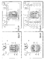
- Figure 2 shows an operational position of the assembly.
- the buffer container 2.01 is filled with hot water and the water in the first line 2.22 has cooled down.
- cold water enters the lower port of the buffer container 2.01 while hot water is pressed out of the upper port towards the line 2.23 and the hot water draw-off point (not shown).
- FIG 3 shows the situation in which control means 2.43 senses cold water, and it switches valve 2.42 to its open position as illustrated in figure 4.
- control means 2.41 When the control means 2.41 senses hot water in the first line 2.22 (figure 6) it switches the first valve 2.40 to the second position.
- the flow of hot water is divided in a stream entering the buffer container 2.01 through the upper port, and a stream towards the hot water draw-off point (line 2.23), see figure 7.
- the hot water entering the buffer container presses cold water out of the lower port towards the water discharge line 2.25 (valve 2.42 still open).
- Safety provisions may be provided for detecting malfunctions.
- Figure 9 shows a second embodiment.
- the control means comprise a first temperature sensor 2.13 positioned in the first line 2.22 upstream from the first valve 2.06, a second temperature sensor 2.11 positioned at the bottom of the buffer container 2.01 and a third temperature sensor 2.12 positioned near the lower port outside of the buffer container.
- a control device gathering signals from the temperature sensors and, based upon these, providing control signals for switching the first and second valves.
- thermosensors and control device offers the possibility to measure time intervals between certain events for controlling the operation of the assembly and optimize the operation of the assembly.
- Figure 10 basically corresponds to figure 2.
- Figure 11 is a situation in which the second valve 2.07 has switched to its open position (based on a signal of sensor 2.11) and wherein a flow of cold water into the buffer container 2.01 has occurred.
- Figure 12 basically corresponds to figure 4.
- Figure 13 basically corresponds to figure 6, whereas figures 14 and 15 basically correspond to figures 7 and 8, respectively.
- the buffer container 2.01 in this embodiment is provided with a heating device 2.08 for heating water contained therein.
- Figure 16 illustrates another assembly for delivering hot water according to the invention. It likewise comprises a heater (not shown) for heating water and delivering it through a first line 2.22, and a buffer container 2.01 for water, having a first lower water port connected to the first line and a second upper water port connected to a hot water draw-off point (line 2.23).
- a heater not shown
- a buffer container 2.01 for water, having a first lower water port connected to the first line and a second upper water port connected to a hot water draw-off point (line 2.23).
- the second upper water port of the buffer container is positioned at or near the top of the buffer container and the first lower water port is positioned at or near the bottom of the buffer container.
- the upper port is connected to the first line 2.22 by means of a first valve 2.06 which is switchable between a first position connecting the lower port to and disconnecting the upper port from, respectively, the first line and a second position connecting the upper port to and disconnecting the lower port from, respectively, the first line.
- the lower port by means of a second line 2.48 further is connected to a second valve 2.05 which is switchable between a first position closing the second line and connecting a cold water supply line 2.21 to a cold water draw-off point 2.24, and a second position closing the cold water supply line 2.21 and connecting the second line 2.48 to the cold water draw-off point 2.24.
- Control means are provided for switching the first and second valves, comprising a first temperature sensor 2.13 positioned in the first line 2.22 upstream of the first valve 2.06, a second temperature sensor 2.11 positioned in the buffer container 2.01 near the bottom thereof and a third temperature sensor 2.12 in the second line 2.48. These temperature sensors cooperate with a control device (not illustrated) gathering signals from the temperature sensors and, based upon these, providing control signals for switching the first and second valves.
- buffer container 2.01 again is provided with a heating device 2.08 for heating water contained therein.
- valve leading to a water discharge line has been omitted and that, now, cold water can flow to a cold water draw-off point. This leads to a saving in water costs.
- Figure 17 shows a situation in which the second valve 2.05 has switched to its first position. Cold water can flow directly from the supply line 2.21 towards the cold water draw-off point 2.24.
- Cooled down water from the first line 2.22 can flow to the cold water draw-off point 2.24 when the first valve 2.06 is in its first position and second valve 2.05 in its second position (figure 18).
- the first valve When the temperature sensor 2.13 has sensed hot water, the first valve is switched to its second position (figure 20) and part of the hot water flows into the upper port, while cold water leaves the lower port to the second line 2.48 and towards the cold water draw-off point 2.24. The remaining part of the hot water flows through line 2.23 upwards towards the hot water draw-off line (not illustrated).
- the resulting situation is a combination of figures 20 and 21.
- Figure 22 shows a direct connection between the first line 2.22 and line 2.23 as stated above, but in a situation in which the buffer container 2.01 is nearly filled again with hot water.
- the buffer container will not be under the line pressure of the water supplied through 2.21 and 2.22 allowing the use of more cost effective containers.
- This embodiment contains a pressure relief valve 2.19 that can be used as a water discharching device if discharching over 2.26 is not desired in which case valve 2.10 will block the flow towards 2.26.
- Valve 2.19 also acts as a safety device if externally blocking 2.26 would lead to a pressure build-up in the container. This offers a user the possibility to request draw-off water as wanted. Line 2.26 leads to the combined hot/cold water draw-off point.
- Figures 26-30 relate to an embodiment of the assembly according to the invention, wherein the buffer container 2.01 is divided internally by a division 2.09 in an upper container part and a lower container part.
- the division 2.09 is a perforated plate.
- a heating device 2.08 and temperature sensor 2.11 within the buffer container are positioned on top of the division 2.09.
- Figure 27 shows a stage in which the amount of hot water of the lower container part has been used (pressed out of the upper port) by feeding cold water from the cold water supply line 2.21 into the lower port.
- temperature sensor 2.11 senses cold water
- the heater (not illustrated) is activated and cooled down water from the first line 2.22 is fed into the lower port (figure 28).
- the temperature sensor positioned in the first line 2.22 upstream from the first valve 2.06 senses hot water, it switches the first valve as shown in figure 30. Part of the hot water enters the upper port, whereas another part is available in line 2.23 leading to the hot water draw-off point. Cold water is pressed out of the lower port towards the discharge line 2.25.
- the second valve 2.05 is switched such that no flow can occur through the lower port, and all hot water is directed to line 2.23.
- FIG 31 Yet another embodiment of the assembly for delivering hot water is illustrated in figure 31. It comprises a heater (not shown) for heating water and delivering it through a first line 2.22, a buffer container 2.01 for water, having an upper port and a lower port, and an auxiliary container 2.02 having an upper port and a lower port.
- a heater (not shown) for heating water and delivering it through a first line 2.22
- a buffer container 2.01 for water having an upper port and a lower port
- an auxiliary container 2.02 having an upper port and a lower port.
- the lower port of the buffer container 2.01 is connected to the upper port of the auxiliary container 2.02 by a connecting line 2.50 and the upper port of the buffer container is connected to a hot water draw-off point by line 2.23.
- a first valve 2.06 is positioned between the first line 2.22, connecting line 2.50 and upper port of the buffer container (through line 2.23) which is switchable between a first position closing the first line and disconnecting the connecting line from the first line and upper port of the buffer container, a second position connecting the first line with the connecting line and disconnecting the port from the valve and a third position connecting the first line with the port and disconnecting the connecting line from the valve.
- the lower port of the auxiliary container 2.02 by means of a second line 2.60 further is connected to a second valve 2.05 which is switchable between a first position connecting the second line 2.60 with a cold water supply line 2.21 and with a cold water draw-off point 2.24, a second position connecting the cold water supply line with the cold water draw-off point and disconnecting the second line and a third position connecting the second line with the cold water draw-off point and disconnecting the cold water supply line.
- the lower port of the auxiliary container 2.02 further is connected to a water discharge line 2.25 by means of a third valve 2.07 which is switchable between a first closed position and a second open position.
- Control means are provided for switching the first, second and third valves, comprising a first temperature sensor 2.13 positioned in the first line 2.22 upstream of the first valve 2.06, a second temperature sensor 2.11 in the buffer container 2.01 near the bottom thereof and a third temperature sensor 2.12 in the second line 2.60, cooperating with a control device (not illustrated) gathering signals from the temperature sensors and, based upon these, providing control signals for switching the valves 2.06, 2.05 and 2.07.
- Figure 32 shows the operational position in which cold water from supply line 2.21 flows through second line 2.60, through the auxiliary container 2.02, through connecting line 2.40 and into buffer container 2.01. Hot water leaves the upper port of latter and reaches line 2.23.
- the heater line 2.22 is disconnected by the first valve 2.06.
- the first valve 2.06 is switched (figure 33) and part of the cooled down water in line 2.22 reaches the upper port of the auxiliary container 2.02 and ultimately reaches (through third valve 2.07) the discharge line 2.25.
- the remainder of the cooled down water from line 2.22 enters the lower port of the buffer container while hot water is pressed out of the upper port towards line 2.23.
- Figure 36 shows a preparatory situation in which a calibration of parameters can occur for optimizing the operation.
- the temperature sensors 2,11 and 2.13 in combination with a control timer are used for, if necessary, selecting a cold start mode or a malfunction mode.
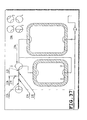
- figure 37 shows an embodiment basically corresponding with the previous one, however with an amended distribution valve 2.06, and measuring devices 2.14, 2.15 and 2.19 for, for example, the mass flow, pressure and temperature.
- the invention is not limited to the embodiments described before, which may be varied widely within the scope of the invention as defined by the appending claims.
- the invention also encompasses a component which basically comprises all parts of the assembly according to any of the previous claims, but without the heater.
- a component can be retrofitted in an existing system to obtain the benefits according to the present invention.
Landscapes
- Engineering & Computer Science (AREA)
- Physics & Mathematics (AREA)
- Thermal Sciences (AREA)
- Mechanical Engineering (AREA)
- General Engineering & Computer Science (AREA)
- Chemical & Material Sciences (AREA)
- Combustion & Propulsion (AREA)
- Devices For Dispensing Beverages (AREA)
Priority Applications (2)
| Application Number | Priority Date | Filing Date | Title |
|---|---|---|---|
| EP06021042A EP1909042A1 (de) | 2006-10-06 | 2006-10-06 | Baugruppe zur Abgabe von warmem Wasser |
| PCT/EP2007/060434 WO2008040721A1 (en) | 2006-10-06 | 2007-10-02 | Assembly for delivering hot water |
Applications Claiming Priority (1)
| Application Number | Priority Date | Filing Date | Title |
|---|---|---|---|
| EP06021042A EP1909042A1 (de) | 2006-10-06 | 2006-10-06 | Baugruppe zur Abgabe von warmem Wasser |
Publications (1)
| Publication Number | Publication Date |
|---|---|
| EP1909042A1 true EP1909042A1 (de) | 2008-04-09 |
Family
ID=37896007
Family Applications (1)
| Application Number | Title | Priority Date | Filing Date |
|---|---|---|---|
| EP06021042A Withdrawn EP1909042A1 (de) | 2006-10-06 | 2006-10-06 | Baugruppe zur Abgabe von warmem Wasser |
Country Status (2)
| Country | Link |
|---|---|
| EP (1) | EP1909042A1 (de) |
| WO (1) | WO2008040721A1 (de) |
Cited By (3)
| Publication number | Priority date | Publication date | Assignee | Title |
|---|---|---|---|---|
| WO2013156019A1 (de) * | 2012-04-18 | 2013-10-24 | Eff-Get Gebäudetechnik Hinxlage Gmbh | Energiemanagementsystem zur pufferspeicherung von kälte- oder wärmeenergie und verfahren zum betreiben des energiemanagementsystems |
| WO2026120253A1 (fr) * | 2024-12-05 | 2026-06-11 | Cresco | Dispositif pour raccorder fluidiquement un chauffe-eau à accumulation à un réseau d'eau sanitaire et chauffe-eau à accumulation comprenant un dispositif de ce type |
| FR3169541A1 (fr) * | 2024-12-05 | 2026-06-12 | Cresco | Chauffe-eau à accumulation comprenant un dispositif pour raccorder fluidiquement le chauffe-eau à un réseau d’eau sanitaire |
Citations (6)
| Publication number | Priority date | Publication date | Assignee | Title |
|---|---|---|---|---|
| GB644687A (en) * | 1948-04-19 | 1950-10-18 | Walter Lorenzo Walters | Improved water heater |
| GB704253A (en) * | 1951-02-13 | 1954-02-17 | Midland Ind Computing | Improvements in or relating to temperature controlled valves for water heaters |
| EP0126605A2 (de) * | 1983-05-23 | 1984-11-28 | Borg-Warner Corporation | Warmwasserspeicher mit Wärmepumpe zur schnellen Warmwassererzeugung |
| US4522254A (en) * | 1981-09-30 | 1985-06-11 | Kajima Kensetsu Kabuhiki Kaisha | Heat storage trough |
| US5588088A (en) * | 1994-06-20 | 1996-12-24 | Flaman; Michael T. | Hot water tempering system utilizing a storage tank, a bypass line and a proportional flow controller |
| EP1450110A2 (de) * | 2003-02-20 | 2004-08-25 | Denso Corporation | Warmwasserversorgungssystem mit Speichertank |
-
2006
- 2006-10-06 EP EP06021042A patent/EP1909042A1/de not_active Withdrawn
-
2007
- 2007-10-02 WO PCT/EP2007/060434 patent/WO2008040721A1/en not_active Ceased
Patent Citations (6)
| Publication number | Priority date | Publication date | Assignee | Title |
|---|---|---|---|---|
| GB644687A (en) * | 1948-04-19 | 1950-10-18 | Walter Lorenzo Walters | Improved water heater |
| GB704253A (en) * | 1951-02-13 | 1954-02-17 | Midland Ind Computing | Improvements in or relating to temperature controlled valves for water heaters |
| US4522254A (en) * | 1981-09-30 | 1985-06-11 | Kajima Kensetsu Kabuhiki Kaisha | Heat storage trough |
| EP0126605A2 (de) * | 1983-05-23 | 1984-11-28 | Borg-Warner Corporation | Warmwasserspeicher mit Wärmepumpe zur schnellen Warmwassererzeugung |
| US5588088A (en) * | 1994-06-20 | 1996-12-24 | Flaman; Michael T. | Hot water tempering system utilizing a storage tank, a bypass line and a proportional flow controller |
| EP1450110A2 (de) * | 2003-02-20 | 2004-08-25 | Denso Corporation | Warmwasserversorgungssystem mit Speichertank |
Cited By (4)
| Publication number | Priority date | Publication date | Assignee | Title |
|---|---|---|---|---|
| WO2013156019A1 (de) * | 2012-04-18 | 2013-10-24 | Eff-Get Gebäudetechnik Hinxlage Gmbh | Energiemanagementsystem zur pufferspeicherung von kälte- oder wärmeenergie und verfahren zum betreiben des energiemanagementsystems |
| WO2026120253A1 (fr) * | 2024-12-05 | 2026-06-11 | Cresco | Dispositif pour raccorder fluidiquement un chauffe-eau à accumulation à un réseau d'eau sanitaire et chauffe-eau à accumulation comprenant un dispositif de ce type |
| FR3169541A1 (fr) * | 2024-12-05 | 2026-06-12 | Cresco | Chauffe-eau à accumulation comprenant un dispositif pour raccorder fluidiquement le chauffe-eau à un réseau d’eau sanitaire |
| FR3169542A1 (fr) * | 2024-12-05 | 2026-06-12 | Cresco | Dispositif pour raccorder fluidiquement un chauffe-eau à accumulation à un réseau d’eau sanitaire |
Also Published As
| Publication number | Publication date |
|---|---|
| WO2008040721A1 (en) | 2008-04-10 |
Similar Documents
| Publication | Publication Date | Title |
|---|---|---|
| US8498527B2 (en) | Water heating control and storage system | |
| AU2010214023B2 (en) | Heat pump water heater control | |
| AU2010200835B2 (en) | A Controllable Water Heater | |
| US20190053656A1 (en) | Beverage machine and method for producing coffee-based beverages | |
| CN104833156A (zh) | 冰箱 | |
| AU2007302868B2 (en) | Device for dispensing water with variable temperatures | |
| KR101040692B1 (ko) | 차압정보를 이용한 비례유량조절시스템 | |
| US9321623B2 (en) | Water dispenser | |
| US10443859B2 (en) | Water heating assembly for providing hot water in a reduced time to a point of use, and related kit, use and method | |
| US7380523B2 (en) | Control for a fuel-fired water heating appliance having variable heating rates | |
| WO2008040721A1 (en) | Assembly for delivering hot water | |
| KR101008670B1 (ko) | 비례제어 온수난방 시스템 | |
| EP2820300B1 (de) | Verdichtervorrichtung und verfahren zur steuerung einer solchen verdichtervorrichtung | |
| JP5705332B2 (ja) | 瞬間湯沸器 | |
| US20040231725A1 (en) | Method and appliance for regulating the inflow of hot water to a container | |
| CN202858842U (zh) | 一种平衡供水调温系统及快加热饮水机 | |
| NL2020522B1 (en) | Improved satellite plumbing unit | |
| EP2244020A2 (de) | Vorrichtung und Verfahren zur Bereitstellung von erhitztem Wasser an einem Abzugspunkt | |
| JP7765983B2 (ja) | 給湯システム | |
| JP2012093060A (ja) | 給湯システム | |
| KR20210004207A (ko) | 배관 잔수 드레인모듈 및 이를 포함하는 배관 잔수 드레인시스템 | |
| GB2368896A (en) | Heat exchange system, temperature sensor arrangement and operation | |
| KR100623671B1 (ko) | 정수기 및 정수기 제어방법 | |
| KR20120095228A (ko) | 일정온도의 온수 공급이 가능한 온수 공급시스템 | |
| KR102236716B1 (ko) | 난방수 이용 급탕 장치 |
Legal Events
| Date | Code | Title | Description |
|---|---|---|---|
| PUAI | Public reference made under article 153(3) epc to a published international application that has entered the european phase |
Free format text: ORIGINAL CODE: 0009012 |
|
| AK | Designated contracting states |
Kind code of ref document: A1 Designated state(s): AT BE BG CH CY CZ DE DK EE ES FI FR GB GR HU IE IS IT LI LT LU LV MC NL PL PT RO SE SI SK TR |
|
| AX | Request for extension of the european patent |
Extension state: AL BA HR MK RS |
|
| AKX | Designation fees paid | ||
| REG | Reference to a national code |
Ref country code: DE Ref legal event code: 8566 |
|
| STAA | Information on the status of an ep patent application or granted ep patent |
Free format text: STATUS: THE APPLICATION IS DEEMED TO BE WITHDRAWN |
|
| 18D | Application deemed to be withdrawn |
Effective date: 20081010 |