EP1909053A2 - Wärmeableitsystem und -verfahren - Google Patents
Wärmeableitsystem und -verfahren Download PDFInfo
- Publication number
- EP1909053A2 EP1909053A2 EP07251910A EP07251910A EP1909053A2 EP 1909053 A2 EP1909053 A2 EP 1909053A2 EP 07251910 A EP07251910 A EP 07251910A EP 07251910 A EP07251910 A EP 07251910A EP 1909053 A2 EP1909053 A2 EP 1909053A2
- Authority
- EP
- European Patent Office
- Prior art keywords
- condenser
- heat
- working fluid
- cavity body
- receiving part
- Prior art date
- Legal status (The legal status is an assumption and is not a legal conclusion. Google has not performed a legal analysis and makes no representation as to the accuracy of the status listed.)
- Withdrawn
Links
Images


Classifications
-
- F—MECHANICAL ENGINEERING; LIGHTING; HEATING; WEAPONS; BLASTING
- F28—HEAT EXCHANGE IN GENERAL
- F28D—HEAT-EXCHANGE APPARATUS, NOT PROVIDED FOR IN ANOTHER SUBCLASS, IN WHICH THE HEAT-EXCHANGE MEDIA DO NOT COME INTO DIRECT CONTACT
- F28D1/00—Heat-exchange apparatus having stationary conduit assemblies for one heat-exchange medium only, the media being in contact with different sides of the conduit wall, in which the other heat-exchange medium is a large body of fluid, e.g. domestic or motor car radiators
- F28D1/02—Heat-exchange apparatus having stationary conduit assemblies for one heat-exchange medium only, the media being in contact with different sides of the conduit wall, in which the other heat-exchange medium is a large body of fluid, e.g. domestic or motor car radiators with heat-exchange conduits immersed in the body of fluid
- F28D1/0226—Heat-exchange apparatus having stationary conduit assemblies for one heat-exchange medium only, the media being in contact with different sides of the conduit wall, in which the other heat-exchange medium is a large body of fluid, e.g. domestic or motor car radiators with heat-exchange conduits immersed in the body of fluid with an intermediate heat-transfer medium, e.g. thermosiphon radiators
-
- F—MECHANICAL ENGINEERING; LIGHTING; HEATING; WEAPONS; BLASTING
- F28—HEAT EXCHANGE IN GENERAL
- F28D—HEAT-EXCHANGE APPARATUS, NOT PROVIDED FOR IN ANOTHER SUBCLASS, IN WHICH THE HEAT-EXCHANGE MEDIA DO NOT COME INTO DIRECT CONTACT
- F28D15/00—Heat-exchange apparatus with the intermediate heat-transfer medium in closed tubes passing into or through the conduit walls ; Heat-exchange apparatus employing intermediate heat-transfer medium or bodies
- F28D15/02—Heat-exchange apparatus with the intermediate heat-transfer medium in closed tubes passing into or through the conduit walls ; Heat-exchange apparatus employing intermediate heat-transfer medium or bodies in which the medium condenses and evaporates, e.g. heat pipes
- F28D15/0266—Heat-exchange apparatus with the intermediate heat-transfer medium in closed tubes passing into or through the conduit walls ; Heat-exchange apparatus employing intermediate heat-transfer medium or bodies in which the medium condenses and evaporates, e.g. heat pipes with separate evaporating and condensing chambers connected by at least one conduit; Loop-type heat pipes; with multiple or common evaporating or condensing chambers
-
- H—ELECTRICITY
- H10—SEMICONDUCTOR DEVICES; ELECTRIC SOLID-STATE DEVICES NOT OTHERWISE PROVIDED FOR
- H10W—GENERIC PACKAGES, INTERCONNECTIONS, CONNECTORS OR OTHER CONSTRUCTIONAL DETAILS OF DEVICES COVERED BY CLASS H10
- H10W40/00—Arrangements for thermal protection or thermal control
- H10W40/70—Fillings or auxiliary members in containers or in encapsulations for thermal protection or control
- H10W40/73—Fillings or auxiliary members in containers or in encapsulations for thermal protection or control for cooling by change of state
-
- F—MECHANICAL ENGINEERING; LIGHTING; HEATING; WEAPONS; BLASTING
- F28—HEAT EXCHANGE IN GENERAL
- F28D—HEAT-EXCHANGE APPARATUS, NOT PROVIDED FOR IN ANOTHER SUBCLASS, IN WHICH THE HEAT-EXCHANGE MEDIA DO NOT COME INTO DIRECT CONTACT
- F28D21/00—Heat-exchange apparatus not covered by any of the groups F28D1/00 - F28D20/00
- F28D2021/0019—Other heat exchangers for particular applications; Heat exchange systems not otherwise provided for
- F28D2021/0028—Other heat exchangers for particular applications; Heat exchange systems not otherwise provided for for cooling heat generating elements, e.g. for cooling electronic components or electric devices
- F28D2021/0031—Radiators for recooling a coolant of cooling systems
Definitions
- the invention relates to heat dissipation, more particularly to a heat dissipating system and method.
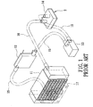
- a liquid-cooling heat dissipating system as disclosed in Taiwanese Publication No. M295424 , includes a heat sink 11 for exchanging heat with external cold air by convection, a thermoelectric cooler 12, a pressure-increasing pump 13 to circulate a working fluid within the system, a liquid-cooling connector 14 in contact with a heat source 2, three input pipes 15 for interconnecting the heat sink 11, the thermoelectric cooler 12, the pump 13, and the liquid-cooling connector 14 in series, an output pipe 16 connected fluidly to the heat sink 11 and the liquid-cooling connector 14, and a fan 17 for directing a current of cold air toward the heat sink 11.
- the heat source 2 may be a central processing unit of a computer.
- the object of the present invention is to provide a heat dissipating system that can reduce noise to a minimum and that can effectively enhance heat dissipation.
- the present invention also provides a method for dissipating heat from a heat source.
- a heat dissipating system comprises: a heat-absorbing unit having at least one cavity body adapted to contact a heat source, and a working fluid received in the cavity body; a condenser to condense the working fluid; and a tubing unit connected fluidly to the condenser and the heat-absorbing unit.
- the working fluid flows through the tubing unit to circulate from the condenser to the heat-absorbing unit by gravity and from the heat-absorbing unit to the condenser by natural convection.
- the tubing unit forms a closed circulating loop with the heat-absorbing unit and the condenser.
- a computer module comprises a housing, at least one chip disposed in the housing, a heat-absorbing unit, a condenser, and a tubing unit.
- the heat-absorbing unit has at least one cavity body contacting the chip, and a working fluid received in the cavity body.
- the condenser is disposed in the housing to condense the working fluid.
- the tubing unit is connected fluidly to the condenser and the heat-absorbing unit.
- the working fluid flows through the tubing unit to circulate from the condenser to the heat-absorbing unit by gravity and from the heat-absorbing unit to the condenser by natural convection.
- the tubing unit forms a closed circulating loop with the heat-absorbing unit and the condenser.
- a method for dissipating heat from a heat source comprises the steps of: (a) contacting the heat source with a heat-absorbing cavity body to cause a working fluid contained in the cavity body to vaporize; (b) allowing the vaporized working fluid to flow upward and enter a condenser by natural convection; (c) condensing the vaporized working fluid in the condenser; (d) cooling the condensed working fluid using a thermoelectric cooler and a heat sink; and (e) allowing the condensed working fluid to flow downward and back into the cavity body by gravity.
- the first preferred embodiment of a heat dissipating system according to the present invention is installed in a computer module 3.
- the computer module 3 has a housing 33 defining upper and lower chambers 31, 32, a mounting board 34 fixed inside the lower chamber 32, and a plurality of module chips 35 mounted on the mounting board 34.
- the heat dissipating system of the present invention comprises a condenser 4, a heat-absorbing unit 5, and a tubing unit 6.
- the module chips 35 are heat sources to undergo heat dissipation by the system of the present invention.
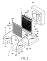
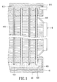
- the condenser 4 is disposed in the upper chamber 31 of the computer module 3, and includes a vapor-receiving part 411 formed on a top end thereof, an inlet 414 connected fluidly to the vapor-receiving part 411, a liquid-receiving part 412 formed on a bottom end thereof, an outlet 415 connected fluidly to the liquid-receiving part 412, a plurality of channels 413 connected between the vapor-receiving and liquid-receiving parts 411, 412, and a thermoelectric cooler 42.
- the thermoelectric cooler 42 is controlled through a circuit, and has a cold side 421 in contact with the liquid-receiving part 412, and a hot side 422 opposite to the cold side 421.
- the cold side 421 has a cooling function so as to keep the liquid-receiving part 412 at a constant temperature.
- the heat dissipating system of the present invention further comprises a heat sink 43 and a fan 44.
- the heat sink 43 is disposed adjacent to the condenser 4, and has an L-shaped configuration.
- the heat sink 43 includes a horizontal plate 431 having a contact portion 4311 in contact with the hot side 422 of the thermoelectric cooler 42, a vertical plate 432 extending upwardly from an end periphery of the horizontal plate 431 and parallel to the condenser 4, and a plurality of fins 433 provided on the vertical plate 432.
- the fan 44 is disposed proximate to the condenser 4 and the heat sink 43, and directs a current of cold air toward the condenser 4 and the heat sink 43, as best shown in Figure 5.
- the heat-absorbing unit 5 in this embodiment, includes first, second, and third cavity bodies 51, 52, 53 respectively in contact with the chips 35 of the computer module 3.
- Each of the first to third cavity bodies 51, 52, 53 has an inlet 511, 521, 531, and an outlet 512, 522, 532.
- the inlet 414 and the outlet 415 of the condenser 4 are disposed at a level higher than those of the first to third cavity bodies 51, 52, 53.
- the tubing unit 6, in this embodiment, includes first, second, third, and fourth tubes 61, 62, 63, 64.
- the first tube 61 is connected to the outlet 415 of the condenser 4 and to the inlet 511 of the first cavity body 51.
- the second tube 62 is connected to the outlet 512 of the first cavity body 51 and to the inlet 521 of the second cavity body 52.
- the third tube 63 is connected to the outlet 522 of the second cavity body 52 and to the inlet 531 of the third cavity body 53.
- the fourth tube 64 is connected to the outlet 532 of the third cavity body 53 and to the inlet 414 of the condenser 4.
- the first to fourth tubes 61, 62, 63, 64, the condenser 4, and the first to third cavity bodies 51, 52, 53 form a closed circulating loop, as best shown in Figure 4.
- a working fluid 30 is injected into the system of the present invention after the first to fourth tubes 61, 62, 63, 64, the first to third cavity bodies 51, 52, 53, and the condenser 4 are evacuated, so that the working fluid 30 circulates in a vacuum environment.
- the working fluid 30 is a coolant that is in a liquid state at room temperature.
- the working fluid 30 may be a super-thermal-conductive liquid.
- the first, second, and third cavity bodies 51, 52, 53 are placed in contact with the respective chips 35, which have the lowest, medium, and highest temperatures, respectively.
- the working fluid 30 is in a liquid state and is in the first and second cavity bodies 51, 52.
- the liquid-state working fluid 30 in the first and second cavity bodies 51, 52 is vaporized.
- the pressure inside the first cavity body 51 increases, the working fluid 30 in a vaporized state flows into the second cavity body 52 through the second tube 62.
- the liquid-state working fluid 30 in the second cavity body 52 is pressurized and is caused to flow through the third tube 63 and into the third cavity body 53 where the temperature is the highest.
- the liquid-state working fluid 30 is vaporized in the third cavity body 53.
- the number of tubes of the tubing unit 6 can be set according to the number of the module chips 35. As such, the working fluid 30 can flow successively from the lowest- to the highest-temperature module chips 35 through the cavity bodies 51, 52, 53.
- step 72 the vaporized working fluid 30 flows upward by natural convection through the fourth tube 64 from a high-density region, which is the third cavity body 53, into a low-density region, which is the vapor-receiving part 411 of the condenser 4.
- step 73 the fan 44 blows cold air toward the condenser 4 and the heat sink 43 so that the condenser 4 and the heat sink 43 exchange heat with the cold air.
- the vaporized working fluid 30 from the fourth tube 64 is condensed in the condenser 4, and flows downward through the channels 413 by gravity into the liquid-receiving part 412.
- step 74 through the cooling function of the cold side 421 of the thermoelectric cooler 42, the temperature of the working fluid 30 in a condensed state and in the liquid-receiving part 412 continues to drop to a preset value, and the hot side 422 of the thermoelectric cooler 42 transfers the heat from the condensed working fluid 30 to the heat sink 43, which dissipates the heat.
- step 75 the cooled condensed working fluid 30 in the liquid-receiving part 412 then flows back into the first cavity body 51 through the first tube 61 by gravity so as to repeat the aforementioned steps.
- the tubing unit 6 includes spaced-apart first and second manifolds 65, 67, three spaced-apart first tubes 66 each connected between the first manifold 65 and the inlet 511, 521, 531 of the respective cavity body 51, 52, 53 so as to direct the liquid-state working fluid 30 into the respective cavity body 51, 52, 53, three spaced-apart second tubes 68 each connected between the second manifold 67 and the outlet 512, 522, 532 of the respective cavity body 51, 52, 53 so as to direct the vaporized working fluid 30 into the second manifold 67, a third tube 69 connected between the first manifold 65 and the liquid-receiving part 412 (see Figure 2) of the condenser 4, and a fourth tube (69') connected between the second manifold 67 and the vapor-receiving part 411
- the condensed working fluid 30 in the liquid-receiving part 412 of the condenser 4 flows down first into the first manifold 65 by gravity, and enters simultaneously the first to third cavity bodies 51, 52, 53 through the first tubes 66.
- the vaporized working fluid 30 in the first to third cavity bodies 51, 52, 53 is collected at the second manifold 67, and from the second manifold 67, the vaporized working fluid 30 flows through the fourth tube 69' and into the vapor-receiving part 411 of the condenser 4.
- the working fluid 30 can self-circulate through the condenser 4, the first to third cavity bodies 51, 52, 53, and the first to fourth tubes 66, 68, 69, 69' , thereby effectively dissipating the heat in the system.
- the heat dissipating system and method according to the third preferred embodiment of the present invention is shown to be similar to the second preferred embodiment.
- the heat-absorbing unit 5 includes five cavity bodies 54 connected in parallel to each other using the first and second manifolds 65, 67 of the tubing unit 6.
- Each cavity body 54 is in contact with an electronic component 7 that can generate heat.
- the arrangement of the tubing unit 6 is as illustrated in Figure 8.
- the heat dissipating system and method of the present invention may also be applicable to dissipating heat of an engine or a machine of a car, or any other article that needs heat dissipation.
Landscapes
- Engineering & Computer Science (AREA)
- Physics & Mathematics (AREA)
- Thermal Sciences (AREA)
- Mechanical Engineering (AREA)
- General Engineering & Computer Science (AREA)
- Life Sciences & Earth Sciences (AREA)
- Sustainable Development (AREA)
- Cooling Or The Like Of Semiconductors Or Solid State Devices (AREA)
- Cooling Or The Like Of Electrical Apparatus (AREA)
Applications Claiming Priority (1)
| Application Number | Priority Date | Filing Date | Title |
|---|---|---|---|
| CN200610142190.6A CN101155497A (zh) | 2006-09-29 | 2006-09-29 | 相变散热装置与方法 |
Publications (2)
| Publication Number | Publication Date |
|---|---|
| EP1909053A2 true EP1909053A2 (de) | 2008-04-09 |
| EP1909053A3 EP1909053A3 (de) | 2008-07-23 |
Family
ID=38780800
Family Applications (1)
| Application Number | Title | Priority Date | Filing Date |
|---|---|---|---|
| EP07251910A Withdrawn EP1909053A3 (de) | 2006-09-29 | 2007-05-09 | Wärmeableitsystem und -verfahren |
Country Status (2)
| Country | Link |
|---|---|
| EP (1) | EP1909053A3 (de) |
| CN (1) | CN101155497A (de) |
Cited By (10)
| Publication number | Priority date | Publication date | Assignee | Title |
|---|---|---|---|---|
| US8893513B2 (en) | 2012-05-07 | 2014-11-25 | Phononic Device, Inc. | Thermoelectric heat exchanger component including protective heat spreading lid and optimal thermal interface resistance |
| US8991194B2 (en) | 2012-05-07 | 2015-03-31 | Phononic Devices, Inc. | Parallel thermoelectric heat exchange systems |
| EP2687319A4 (de) * | 2012-01-05 | 2015-05-20 | Huawei Tech Co Ltd | Wärmerohrstrahler mit einer schwerkraftschaltung, kondensator und herstellungsverfahren dafür |
| CN104669984A (zh) * | 2015-02-13 | 2015-06-03 | 陈春平 | 车载lng换热器及安装该换热器的冷藏运输车 |
| US9593871B2 (en) | 2014-07-21 | 2017-03-14 | Phononic Devices, Inc. | Systems and methods for operating a thermoelectric module to increase efficiency |
| CN109584950A (zh) * | 2018-12-29 | 2019-04-05 | 长兴旗滨玻璃有限公司 | 用于仪表的冷却降温系统 |
| US10458683B2 (en) | 2014-07-21 | 2019-10-29 | Phononic, Inc. | Systems and methods for mitigating heat rejection limitations of a thermoelectric module |
| CN111081665A (zh) * | 2019-10-31 | 2020-04-28 | 中南大学 | 一种用于多热源器件散热的装置 |
| WO2020084956A1 (ja) * | 2018-10-24 | 2020-04-30 | 株式会社デンソー | 温度調整装置 |
| WO2024174538A1 (zh) * | 2023-02-20 | 2024-08-29 | 华为技术有限公司 | 一种散热系统、电子设备和机柜 |
Families Citing this family (5)
| Publication number | Priority date | Publication date | Assignee | Title |
|---|---|---|---|---|
| CN102929366A (zh) * | 2011-08-12 | 2013-02-13 | 英业达股份有限公司 | 冷却系统 |
| CN103105913B (zh) * | 2011-11-14 | 2016-09-21 | 英业达股份有限公司 | 散热系统 |
| CN108781523A (zh) * | 2015-12-29 | 2018-11-09 | 祖达科尔有限公司 | 基于真空的热管理系统 |
| CN107577321B (zh) * | 2017-10-26 | 2023-09-29 | 航天特种材料及工艺技术研究所 | 一种基于相变材料的散热器 |
| US20220217875A1 (en) * | 2019-04-05 | 2022-07-07 | Phase Change Energy Solutions, Inc. | Thermal Management Devices and Methods |
Family Cites Families (8)
| Publication number | Priority date | Publication date | Assignee | Title |
|---|---|---|---|---|
| US5343940A (en) * | 1992-10-29 | 1994-09-06 | Amigo Jean | Flexible heat transfer device |
| KR100338810B1 (ko) * | 1999-11-08 | 2002-05-31 | 윤종용 | 냉각장치 |
| US6474074B2 (en) * | 2000-11-30 | 2002-11-05 | International Business Machines Corporation | Apparatus for dense chip packaging using heat pipes and thermoelectric coolers |
| US6536510B2 (en) * | 2001-07-10 | 2003-03-25 | Thermal Corp. | Thermal bus for cabinets housing high power electronics equipment |
| US6704200B2 (en) * | 2002-02-12 | 2004-03-09 | Hewlett-Packard Development Company, L.P. | Loop thermosyphon using microchannel etched semiconductor die as evaporator |
| SE0301381D0 (sv) * | 2003-05-12 | 2003-05-12 | Sapa Ab | Extruded heat sink with integrated thermosyphon |
| US7184265B2 (en) * | 2003-05-29 | 2007-02-27 | Lg Electronics Inc. | Cooling system for a portable computer |
| US6917522B1 (en) * | 2003-12-29 | 2005-07-12 | Intel Corporation | Apparatus and method for cooling integrated circuit devices |
-
2006
- 2006-09-29 CN CN200610142190.6A patent/CN101155497A/zh active Pending
-
2007
- 2007-05-09 EP EP07251910A patent/EP1909053A3/de not_active Withdrawn
Cited By (17)
| Publication number | Priority date | Publication date | Assignee | Title |
|---|---|---|---|---|
| EP2687319A4 (de) * | 2012-01-05 | 2015-05-20 | Huawei Tech Co Ltd | Wärmerohrstrahler mit einer schwerkraftschaltung, kondensator und herstellungsverfahren dafür |
| US8893513B2 (en) | 2012-05-07 | 2014-11-25 | Phononic Device, Inc. | Thermoelectric heat exchanger component including protective heat spreading lid and optimal thermal interface resistance |
| US8991194B2 (en) | 2012-05-07 | 2015-03-31 | Phononic Devices, Inc. | Parallel thermoelectric heat exchange systems |
| US10012417B2 (en) | 2012-05-07 | 2018-07-03 | Phononic, Inc. | Thermoelectric refrigeration system control scheme for high efficiency performance |
| US9103572B2 (en) | 2012-05-07 | 2015-08-11 | Phononic Devices, Inc. | Physically separated hot side and cold side heat sinks in a thermoelectric refrigeration system |
| US9234682B2 (en) | 2012-05-07 | 2016-01-12 | Phononic Devices, Inc. | Two-phase heat exchanger mounting |
| US9310111B2 (en) | 2012-05-07 | 2016-04-12 | Phononic Devices, Inc. | Systems and methods to mitigate heat leak back in a thermoelectric refrigeration system |
| US9341394B2 (en) | 2012-05-07 | 2016-05-17 | Phononic Devices, Inc. | Thermoelectric heat exchange system comprising cascaded cold side heat sinks |
| US9593871B2 (en) | 2014-07-21 | 2017-03-14 | Phononic Devices, Inc. | Systems and methods for operating a thermoelectric module to increase efficiency |
| US10458683B2 (en) | 2014-07-21 | 2019-10-29 | Phononic, Inc. | Systems and methods for mitigating heat rejection limitations of a thermoelectric module |
| CN104669984B (zh) * | 2015-02-13 | 2017-12-01 | 陈春平 | 车载lng换热器及安装该换热器的冷藏运输车 |
| CN104669984A (zh) * | 2015-02-13 | 2015-06-03 | 陈春平 | 车载lng换热器及安装该换热器的冷藏运输车 |
| WO2020084956A1 (ja) * | 2018-10-24 | 2020-04-30 | 株式会社デンソー | 温度調整装置 |
| CN109584950A (zh) * | 2018-12-29 | 2019-04-05 | 长兴旗滨玻璃有限公司 | 用于仪表的冷却降温系统 |
| CN109584950B (zh) * | 2018-12-29 | 2024-02-02 | 长兴旗滨玻璃有限公司 | 用于仪表的冷却降温系统 |
| CN111081665A (zh) * | 2019-10-31 | 2020-04-28 | 中南大学 | 一种用于多热源器件散热的装置 |
| WO2024174538A1 (zh) * | 2023-02-20 | 2024-08-29 | 华为技术有限公司 | 一种散热系统、电子设备和机柜 |
Also Published As
| Publication number | Publication date |
|---|---|
| CN101155497A (zh) | 2008-04-02 |
| EP1909053A3 (de) | 2008-07-23 |
Similar Documents
| Publication | Publication Date | Title |
|---|---|---|
| US20080078202A1 (en) | Heat dissipating system and method | |
| EP1909053A2 (de) | Wärmeableitsystem und -verfahren | |
| US7525801B2 (en) | Computer module | |
| US6394175B1 (en) | Top mounted cooling device using heat pipes | |
| US7204299B2 (en) | Cooling assembly with sucessively contracting and expanding coolant flow | |
| US7604040B2 (en) | Integrated liquid cooled heat sink for electronic components | |
| US8813834B2 (en) | Quick temperature-equlizing heat-dissipating device | |
| US10201114B2 (en) | Removable board with cooling system for chassis-based electronic equipment | |
| US20060162903A1 (en) | Liquid cooled thermosiphon with flexible partition | |
| US20120087088A1 (en) | Microscale heat transfer systems | |
| WO2017028512A1 (zh) | 单板液冷散热系统及机柜 | |
| US20090272144A1 (en) | Computer cooling apparatus | |
| KR20120006522A (ko) | 소형 장비용 냉각 시스템 | |
| CN106488687B (zh) | 用于对封闭的机柜进行冷却的装置 | |
| TWM512883U (zh) | 散熱模組、水冷式散熱模組及散熱系統 | |
| US20080105404A1 (en) | Heat dissipating system having a heat dissipating cavity body | |
| US20070034355A1 (en) | Heat-dissipation structure and method thereof | |
| EP1923915A2 (de) | Wärmeableitungssystem mit Hohlkörper zur Wärmeableitung | |
| CN215529706U (zh) | 散热装置 | |
| US20100032141A1 (en) | cooling system utilizing carbon nanotubes for cooling of electrical systems | |
| CN115551302B (zh) | 散热系统及电子设备 | |
| EP1923770A1 (de) | Computermodul | |
| CN101726136B (zh) | 两段式膨胀冷却系统及其蒸发器 | |
| US20050135061A1 (en) | Heat sink, assembly, and method of making | |
| US20070151275A1 (en) | Methods and apparatus for microelectronic cooling using a miniaturized vapor compression system |
Legal Events
| Date | Code | Title | Description |
|---|---|---|---|
| PUAI | Public reference made under article 153(3) epc to a published international application that has entered the european phase |
Free format text: ORIGINAL CODE: 0009012 |
|
| AK | Designated contracting states |
Kind code of ref document: A2 Designated state(s): AT BE BG CH CY CZ DE DK EE ES FI FR GB GR HU IE IS IT LI LT LU LV MC MT NL PL PT RO SE SI SK TR |
|
| AX | Request for extension of the european patent |
Extension state: AL BA HR MK RS |
|
| PUAL | Search report despatched |
Free format text: ORIGINAL CODE: 0009013 |
|
| AK | Designated contracting states |
Kind code of ref document: A3 Designated state(s): AT BE BG CH CY CZ DE DK EE ES FI FR GB GR HU IE IS IT LI LT LU LV MC MT NL PL PT RO SE SI SK TR |
|
| AX | Request for extension of the european patent |
Extension state: AL BA HR MK RS |
|
| RIC1 | Information provided on ipc code assigned before grant |
Ipc: H01L 23/427 20060101ALI20080616BHEP Ipc: F28D 15/02 20060101ALI20080616BHEP Ipc: F28D 1/02 20060101AFI20071213BHEP |
|
| AKX | Designation fees paid | ||
| REG | Reference to a national code |
Ref country code: DE Ref legal event code: 8566 |
|
| STAA | Information on the status of an ep patent application or granted ep patent |
Free format text: STATUS: THE APPLICATION IS DEEMED TO BE WITHDRAWN |
|
| 18D | Application deemed to be withdrawn |
Effective date: 20090124 |