EP1909074A1 - Appareil de détection d angle de rotation - Google Patents
Appareil de détection d angle de rotation Download PDFInfo
- Publication number
- EP1909074A1 EP1909074A1 EP06781108A EP06781108A EP1909074A1 EP 1909074 A1 EP1909074 A1 EP 1909074A1 EP 06781108 A EP06781108 A EP 06781108A EP 06781108 A EP06781108 A EP 06781108A EP 1909074 A1 EP1909074 A1 EP 1909074A1
- Authority
- EP
- European Patent Office
- Prior art keywords
- magnet
- rotating
- rotational angle
- magnetic sensor
- angle detection
- Prior art date
- Legal status (The legal status is an assumption and is not a legal conclusion. Google has not performed a legal analysis and makes no representation as to the accuracy of the status listed.)
- Withdrawn
Links
Images



Classifications
-
- G—PHYSICS
- G01—MEASURING; TESTING
- G01D—MEASURING NOT SPECIALLY ADAPTED FOR A SPECIFIC VARIABLE; ARRANGEMENTS FOR MEASURING TWO OR MORE VARIABLES NOT COVERED IN A SINGLE OTHER SUBCLASS; TARIFF METERING APPARATUS; MEASURING OR TESTING NOT OTHERWISE PROVIDED FOR
- G01D5/00—Mechanical means for transferring the output of a sensing member; Means for converting the output of a sensing member to another variable where the form or nature of the sensing member does not constrain the means for converting; Transducers not specially adapted for a specific variable
- G01D5/12—Mechanical means for transferring the output of a sensing member; Means for converting the output of a sensing member to another variable where the form or nature of the sensing member does not constrain the means for converting; Transducers not specially adapted for a specific variable using electric or magnetic means
- G01D5/14—Mechanical means for transferring the output of a sensing member; Means for converting the output of a sensing member to another variable where the form or nature of the sensing member does not constrain the means for converting; Transducers not specially adapted for a specific variable using electric or magnetic means influencing the magnitude of a current or voltage
- G01D5/142—Mechanical means for transferring the output of a sensing member; Means for converting the output of a sensing member to another variable where the form or nature of the sensing member does not constrain the means for converting; Transducers not specially adapted for a specific variable using electric or magnetic means influencing the magnitude of a current or voltage using Hall-effect devices
- G01D5/145—Mechanical means for transferring the output of a sensing member; Means for converting the output of a sensing member to another variable where the form or nature of the sensing member does not constrain the means for converting; Transducers not specially adapted for a specific variable using electric or magnetic means influencing the magnitude of a current or voltage using Hall-effect devices influenced by the relative movement between the Hall device and magnetic fields
-
- G—PHYSICS
- G01—MEASURING; TESTING
- G01R—MEASURING ELECTRIC VARIABLES; MEASURING MAGNETIC VARIABLES
- G01R33/00—Arrangements or instruments for measuring magnetic variables
- G01R33/0005—Geometrical arrangement of magnetic sensor elements; Apparatus combining different magnetic sensor types
-
- G—PHYSICS
- G01—MEASURING; TESTING
- G01R—MEASURING ELECTRIC VARIABLES; MEASURING MAGNETIC VARIABLES
- G01R33/00—Arrangements or instruments for measuring magnetic variables
- G01R33/02—Measuring direction or magnitude of magnetic fields or magnetic flux
- G01R33/06—Measuring direction or magnitude of magnetic fields or magnetic flux using galvano-magnetic devices
- G01R33/09—Magnetoresistive devices
- G01R33/091—Constructional adaptation of the sensor to specific applications
Definitions
- the present invention relates to a rotational angle detection device, which uses a magnetic sensor with bridge-connected magnetoresistive effect elements (hereinafter, referred to as "MR elements”) to detect a rotational angle of a detection object.
- MR elements magnetoresistive effect elements
- a rotational angle detection device of non-contact type using an MR sensor is known that is used to detect a rotationalangle of a rotating shaft as a detection object, as disclosed in, e.g., Patent Document 1.
- a rotational angle detection device comprises: a rotating magnet 102, which is attached to a rotating shaft 101 as a detection object and rotated with the rotating shaft 101; and a magnetic sensor 103, which is positioned in the vicinity of the rotating magnet 102, without contacting with the rotating shaft 101.
- the magnetic sensor 103 comprises a pair of sensor units 121 and 122, each with bridge-connected four MR elements 111, respectively, as illustrated in FIG. 10 , etc.
- Each of the four MR elements 111 that configure each of the sensor units 121 and 122 have magnetic anisotropy as their physical attribute, respectively. That is, the MR elements 111 provide different resistance values in magnetic fields along a easy-magnetization axis from those in magnetic fields along a difficult-magnetization axis perpendicular to the easy-magnetization axis.
- the four MR elements 111 that configure the sensor units 121 or 122 are positioned in such a way that their easy-magnetization axes are displaced by an angle of 90° with respect to each other.
- each MR element 111 in the sensor unit 121 and each MR element 111 in the sensor unit 122 are positioned in such a way that their easy-magnetization axis are tilted by an angle of 45°with respect to each other.
- the magnetic sensor 103 is positioned in a homogeneous magnetic field of the rotating magnet 102 on a substrate 104.
- the rotating magnet 102 which is attached to the rotating shaft 101, rotates accordingly, thereby providing a rotating magnetic field in the magnetic sensor 103.
- the magnetic sensor 103 outputs a sinusoidal signal.
- a rotational angle of the rotating shaft 101 can be detected from that sinusoidal signal.
- the above-mentioned magnetic sensor 103 since the above-mentioned magnetic sensor 103, by its nature, has only an detectable angle range of 180°, from one easy-magnetization axis at the plus-end to the other easy-magnetization axis at the minus-end, it could not univocally detect an angle ranging from 0° to 360°.
- Patent Document 3 Japanese Patent Laid-Open No. 2003-4480
- Patent Document 2 does not disclose any relationship in detail for rotational angles of rotating magnets.
- An object of the present invention is to provide a rotational angle detection device that may detect rotational angle ranging from 0° to 360° with an extremely simple configuration.
- a rotational angle detection device comprises: a rotating magnet attached to a detection object and rotated with the detection object to generate a rotating magnetic field; a magnetic sensor positioned in a rotating magnetic field generated by the rotating magnet to position sensor units with bridge-connected magneticresistive effect elements in such a way that their easy-magnetization axis are displaced by an angle of 45°; and a four-pole auxiliary magnet positioned in the vicinity of the magnetic sensor to generate a combined rotating magnetic field ranging from 0° to 180°, from a rotating magnetic field ranging from 0° to 360° provided by the rotating magnet in a region where the magnetic sensor is positioned.
- the magnitude of a magnetic moment of the rotating magnet and a synthesized magnetic moment of the four-pole auxiliary magnet, each being provided to the magnetic sensor is substantially the same.
- the four-pole auxiliary magnet is, e.g., a ring-shaped magnet that is positioned in parallel to a rotating surface of the rotating magnet.
- the four-pole auxiliary magnet is coaxially positioned with respect to a rotating shaft of the rotating magnet; and the magnetic sensor is positioned in a homogeneous magnetic field of the four-pole auxiliary magnet.
- the four-pole magnet is positioned in a displaced position with respect to the rotating shaft and on the same surface as a rotating surface of the rotating magnet; and the magnetic sensor is positioned in the homogeneous magnetic field of the four-pole magnet.
- a synthesized magnetic moment between a synthesized magnetic moment of the four-pole auxiliary magnet and a magnetic moment obtained from a rotating magnet serves to convert a rotational angle ranging from 0° to 360° provided by the rotating magnet into a rotational angle ranging from 0° to 180°. This enables a detected value for a rotational angle between 0° and 180° at the magnetic sensor to be obtained as a detected value for a rotational angle between 0° and 360° for the detection object.
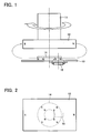
- FIG. 1 is a side view illustrating a configuration of a rotational angle detection device according to a first embodiment of the present invention
- FIG. 2 is a plan view of the same device.
- the rotational angle detection device comprises: a rotating magnet 12, which is mounted on one end of a rotating shaft 11 as a detection object; a four-pole auxiliary magnet 14, which is mounted on a substrate 13 opposed to the rotating magnet 12 without contact; and a magnetic sensor 15, which is mounted on the opposite side of the substrate 13.
- the detection object is the rotating shaft 11 of a motor or the like.
- shaft ends of the rotating shaft 11 can be used as a detection object.
- the rotating magnet 12, which has a shape of rectangular parallelepiped, is a two-pole permanent magnet with its poles being provided at both ends in its longitudinal direction.
- the four-pole auxiliary magnet 14 is a ring-shaped magnet that is coaxially positioned with respect to the rotating shaft 11. Additionally, in FIG. 2 , the four-pole auxiliary magnet 14 is magnetized so as to form a magnetic moment in a direction of +45° and -45° with respect to the horizontal center line.
- the magnetic sensor 15, which is similar to that in FIG. 10 is mounted on a displaced position with respect to the rotational center so that it would be positioned in a homogeneous magnetic field generated by the rotating magnet 12 and the four-pole auxiliary magnet 14.
- FIG. 3 illustrates a signal processing circuit connected to the magnetic sensor 15.
- Each detected signal that is output from each output terminal D, E, B and G of the magnetic sensor 15 is subject to A/D conversion at A/D conversion circuits 21 to 24, and then input to a CPU 25.
- the CPU 25 performs a certain signal processing according to a program stored in an EEPROM 26 and calculates rotational angle detection data.
- the detected data is converted into an analog signal by a D/A conversion circuit 27 and output as a rotational angle detection signal Vo.
- FIG. 4 illustrates a relationship between values Mr, Mh, M, ⁇ and ⁇ , wherein the X axis represents a horizontal direction in FIG. 2 ; the Y-axis represents a vertical direction; Mr represents a magnetic moment of the rotating magnet 12; Mh represents a synthesized magnetic moment of the four-pole auxiliary magnet 14; M represents a synthesized magnetic moment of Mr and Mh; and " ⁇ " and ⁇ represents a rotationalangle of each magnetic moment Mr and M, respectively. Between these, the following relationship is obtained:
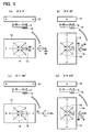
- FIGS. 5(a) to 5(d) illustrate those variations in a synthesized magnetic moment M that affect the magnetic sensor 15 when the rotating magnet 12 sequentially rotates to 0°, 90°, 180° and 270°, each angle corresponding to a rotational angle ⁇ of the rotating magnet 12 in these drawings.
- Step 1 First, the magnetic sensor 15 and the four-pole auxiliary magnet 14 are positioned in such a way that their reference axis forms an angle of 0°. For this purpose, the following steps 1a and 1b are performed.
- Step 1a The magnetic sensor 15 and the signal processing circuit are positioned in a marked position in the lower surface of the substrate 13 so that the angle between the reference axes of the substrate 13 and the magnetic sensor 15 is 0°.
- Step 1b Offsets are calibrated while monitoring an output signal Vo from the signal processing circuit, with an oscilloscope or the like. Then, the four-pole auxiliary magnet 14 is positioned in a marked position in the upper surface of the substrate 13 (on the side of the rotating magnet 12) so that the output signal Vo becomes a value indicating 0° as being read by a digital multi-meter.
- Step 2 Next, the rotating magnet 12 and the four-pole auxiliary magnet 14 are positioned in such a way that their magnetic moments Mh and Mr are orthogonal to each other (so as to have a relationship as illustrated in FIG. 5(b) ). For this purpose, the following steps 2a and 2b are performed.
- Step 2a Based on 0° that was determined at step 1, and similar to step 1b, the rotating magnet 12 is located so that the output signal Vo from the signal processing circuit becomes a value indicating 0° as being read by the digital multimeter. This position is regarded as a reference position 0°of the rotating magnet 12.
- Step 2b In order to rotate the rotating magnet 12 by 90° with respect to the reference position 0° of the rotating magnet 12 that was determined at step 2a, for example, an absolute encoder (e.g., MAR-M30 manufactured by Nikon Corporation or its equivalent) is used.
- FIG. 7 is a side view illustrating a configuration of a rotational angle detection device according to a second embodiment of the present invention. This embodiment is suitable for a case where such shaft ends may not be available because a steering angle of an automobile is detected from a shaft rotational angle of an assisting electric motor.
- a rotating shaft 31 as the detection object is equipped with a ring-shaped rotating magnet 32.
- a ring-shaped four-pole auxiliary magnet 34 is mounted on a substrate 33 that is positioned on the same surface as the rotating surface of the rotating magnet 32.
- a magnetic sensor 35 is mounted on the rear surface of the substrate 33. The magnetic sensor 35, which is similar to that in FIG. 10 , is mounted on a displaced position with respect to the center of the four-pole auxiliary magnet 34 so that it would be positioned in a homogenous magnetic field generated by the four-pole auxiliary magnet 34.
- the synthesized magnetic moment M would vary within the range of 0° to 180°, from 0° to 90° and from -90° to 0°, for rotations of 0° to 360° provided by the rotating magnet 32. Therefore, by detecting those changes by the magnetic sensor 35, changes in rotationalangle of the rotating shaft 31 can be detected within the range of 0° to 360°.
- the four-pole auxiliary magnet is not necessarily limited to have an annular shape.
- an elliptic magnet also can be used for the four-pole auxiliary magnet.
- four-pole magnetization can be performed in a symmetric direction to the short or long axis.
Landscapes
- Physics & Mathematics (AREA)
- General Physics & Mathematics (AREA)
- Condensed Matter Physics & Semiconductors (AREA)
- Transmission And Conversion Of Sensor Element Output (AREA)
- Measurement Of Length, Angles, Or The Like Using Electric Or Magnetic Means (AREA)
Applications Claiming Priority (2)
| Application Number | Priority Date | Filing Date | Title |
|---|---|---|---|
| JP2005209396A JP3848670B1 (ja) | 2005-07-20 | 2005-07-20 | 回転角度検出装置 |
| PCT/JP2006/314034 WO2007010842A1 (fr) | 2005-07-20 | 2006-07-14 | Appareil de détection d’angle de rotation |
Publications (2)
| Publication Number | Publication Date |
|---|---|
| EP1909074A1 true EP1909074A1 (fr) | 2008-04-09 |
| EP1909074A4 EP1909074A4 (fr) | 2010-09-29 |
Family
ID=37544641
Family Applications (1)
| Application Number | Title | Priority Date | Filing Date |
|---|---|---|---|
| EP06781108A Withdrawn EP1909074A4 (fr) | 2005-07-20 | 2006-07-14 | Appareil de détection d angle de rotation |
Country Status (5)
| Country | Link |
|---|---|
| US (1) | US7808234B2 (fr) |
| EP (1) | EP1909074A4 (fr) |
| JP (1) | JP3848670B1 (fr) |
| CN (1) | CN101253389B (fr) |
| WO (1) | WO2007010842A1 (fr) |
Cited By (2)
| Publication number | Priority date | Publication date | Assignee | Title |
|---|---|---|---|---|
| DE102015001553B3 (de) * | 2014-04-10 | 2015-08-27 | Micronas Gmbh | Sensorvorrichtung |
| EP2944924B1 (fr) * | 2013-01-11 | 2020-10-21 | Multidimension Technology Co., Ltd. | Codeur électromagnétique absolu multitour |
Families Citing this family (24)
| Publication number | Priority date | Publication date | Assignee | Title |
|---|---|---|---|---|
| EP1830162B1 (fr) * | 2004-12-14 | 2015-04-01 | NTN Corporation | Dispositif de detection de rotation et roulement muni de celui-ci |
| JP5053150B2 (ja) * | 2008-03-28 | 2012-10-17 | 古河電気工業株式会社 | 回転角度検出方法及び回転角度検出装置 |
| JP2009244044A (ja) * | 2008-03-31 | 2009-10-22 | Tokai Rika Co Ltd | 磁気式回転位置検出装置 |
| US20120098529A1 (en) * | 2009-06-30 | 2012-04-26 | Tomen Electronics Corporation | Rotation angle detecting device |
| WO2011057769A1 (fr) * | 2009-11-10 | 2011-05-19 | Daimler Ag | Électrolyte conducteur de protons composite contenant des additifs améliorés pour piles à combustible |
| US20120242331A1 (en) * | 2009-12-04 | 2012-09-27 | Werner Dengler | Hall-based rotational angle measuring system, in particular for hand-operated throttles |
| FR2953805B1 (fr) * | 2009-12-15 | 2011-12-30 | Ratier Figeac Soc | Dispositif de pilotage d'un aeronef a elements magneto-sensibles de detection de position angulaire montes hors axe |
| EP2354769B1 (fr) | 2010-02-03 | 2015-04-01 | Micronas GmbH | Capteur angulaire et procédé de détermination d'un angle entre un agencement de capteurs et un champ magnétique |
| US8779760B2 (en) | 2011-06-09 | 2014-07-15 | Infineon Technologies Ag | Angle measurement system including magnet with substantially square face for through-shaft applications |
| JP2013253878A (ja) * | 2012-06-07 | 2013-12-19 | Mikuni Corp | 角度センサ |
| JP6205774B2 (ja) | 2013-03-22 | 2017-10-04 | セイコーエプソン株式会社 | 検出回路、半導体集積回路装置、磁界回転角検出装置、及び、電子機器 |
| JP6190157B2 (ja) * | 2013-05-16 | 2017-08-30 | アズビル株式会社 | 回転角度検出器 |
| JP2015052557A (ja) * | 2013-09-09 | 2015-03-19 | 株式会社東海理化電機製作所 | 磁気式位置検出装置 |
| DE102014205566A1 (de) * | 2014-03-26 | 2015-10-01 | Robert Bosch Gmbh | Sensoranordnung zur Wegerfassung an einem bewegten Bauteil |
| DE102014004625A1 (de) * | 2014-03-31 | 2015-10-01 | Micronas Gmbh | Sensorvorrichtung |
| CN204421990U (zh) * | 2015-01-14 | 2015-06-24 | 江苏多维科技有限公司 | 一种可消除相邻转轮磁干涉的直读表 |
| CN205066678U (zh) * | 2015-10-26 | 2016-03-02 | 深圳市道通智能航空技术有限公司 | 角位移检测装置、电机转角控制系统、云台和飞行器 |
| US10006789B2 (en) * | 2016-04-27 | 2018-06-26 | Tdk Corporation | Correction apparatus for angle sensor, and angle sensor |
| DE102016118384B4 (de) | 2016-09-28 | 2023-10-26 | Infineon Technologies Ag | Magnetische Winkelsensorvorrichtung und Betriebsverfahren |
| CN207424353U (zh) * | 2017-01-03 | 2018-05-29 | 台湾东电化股份有限公司 | 光学机构 |
| US10606030B2 (en) | 2017-01-03 | 2020-03-31 | Tdk Taiwan Corp. | Optical mechanism |
| FR3082615B1 (fr) | 2018-06-15 | 2020-10-16 | Electricfil Automotive | Methode de determination d'une position angulaire relative entre deux pieces |
| DE102018123885A1 (de) * | 2018-09-27 | 2020-04-02 | Thyssenkrupp Ag | Winkelsensor mit zweipoligem Magnet für eine Kraftfahrzeuglenkung |
| FR3087256B1 (fr) | 2018-10-15 | 2020-10-30 | Electricfil Automotive | Methode et systeme capteur de determination d'une position angulaire relative entre deux pieces, et procede de fabrication d'un corps magnetique |
Family Cites Families (11)
| Publication number | Priority date | Publication date | Assignee | Title |
|---|---|---|---|---|
| DE4408078A1 (de) | 1994-03-10 | 1995-09-14 | Philips Patentverwaltung | Winkelsensor |
| US5627465A (en) * | 1995-10-25 | 1997-05-06 | Honeywell Inc. | Rotational position sensor with mechanical adjustment of offset and gain signals |
| US6064197A (en) | 1997-07-26 | 2000-05-16 | U.S. Philips Corporation | Angle sensor having lateral magnetic field sensor element and axial magnetic field direction measuring element for determining angular position |
| US6326781B1 (en) * | 1999-01-11 | 2001-12-04 | Bvr Aero Precision Corp | 360 degree shaft angle sensing and remote indicating system using a two-axis magnetoresistive microcircuit |
| US6448763B1 (en) * | 2001-01-10 | 2002-09-10 | Siemens Corporation | System for magnetization to produce linear change in field angle |
| DE10118650A1 (de) | 2001-04-14 | 2002-10-17 | Philips Corp Intellectual Pty | Winkelsensor sowie Verfahren zum Erhöhen der Anisotropiefeldstärke einer Sensoreinheit eines Winkelsensors |
| US7208940B2 (en) * | 2001-11-15 | 2007-04-24 | Honeywell International Inc. | 360-Degree magnetoresistive rotary position sensor |
| US20040012385A1 (en) * | 2002-07-16 | 2004-01-22 | Kirkpatrick Richard A. | Apparatus and method for generating an offset voltage for angular position calculations |
| US6791219B1 (en) * | 2003-06-18 | 2004-09-14 | Bvr Technologies Company | Contactless electro-mechanical actuator with coupled electronic motor commutation and output position sensors |
| WO2004113928A2 (fr) | 2003-06-25 | 2004-12-29 | Philips Intellectual Property & Standards Gmbh | Agencement avec un capteur d'angle en fonction du champ magnetique |
| JP2005024282A (ja) * | 2003-06-30 | 2005-01-27 | Sendai Nikon:Kk | 磁気式エンコーダ |
-
2005
- 2005-07-20 JP JP2005209396A patent/JP3848670B1/ja not_active Expired - Fee Related
-
2006
- 2006-07-14 EP EP06781108A patent/EP1909074A4/fr not_active Withdrawn
- 2006-07-14 CN CN2006800262192A patent/CN101253389B/zh not_active Expired - Fee Related
- 2006-07-14 WO PCT/JP2006/314034 patent/WO2007010842A1/fr not_active Ceased
- 2006-07-14 US US11/988,215 patent/US7808234B2/en not_active Expired - Fee Related
Cited By (3)
| Publication number | Priority date | Publication date | Assignee | Title |
|---|---|---|---|---|
| EP2944924B1 (fr) * | 2013-01-11 | 2020-10-21 | Multidimension Technology Co., Ltd. | Codeur électromagnétique absolu multitour |
| DE102015001553B3 (de) * | 2014-04-10 | 2015-08-27 | Micronas Gmbh | Sensorvorrichtung |
| US10018684B2 (en) | 2014-04-10 | 2018-07-10 | Tdk-Micronas Gmbh | Sensor device |
Also Published As
| Publication number | Publication date |
|---|---|
| US7808234B2 (en) | 2010-10-05 |
| JP2007024738A (ja) | 2007-02-01 |
| JP3848670B1 (ja) | 2006-11-22 |
| EP1909074A4 (fr) | 2010-09-29 |
| US20090033321A1 (en) | 2009-02-05 |
| WO2007010842A1 (fr) | 2007-01-25 |
| CN101253389B (zh) | 2010-09-29 |
| CN101253389A (zh) | 2008-08-27 |
Similar Documents
| Publication | Publication Date | Title |
|---|---|---|
| US7808234B2 (en) | Rotational angle detection device with a rotating magnet and a four-pole auxiiliary magnet | |
| US6707293B2 (en) | 360-degree rotary position sensor having a magnetoresistive sensor and a hall sensor | |
| US8587295B2 (en) | Angle detection apparatus and position detection apparatus | |
| US8193805B2 (en) | Magnetic sensor | |
| CN101939623B (zh) | 旋转角度检测装置、旋转机及旋转角度检测方法 | |
| JP5801566B2 (ja) | 回転角度検出装置 | |
| US20090039872A1 (en) | Rotary encoder and method for operation of a rotary encoder | |
| US10816361B2 (en) | Arrangement for detecting the angular position of a rotatable component | |
| US7208940B2 (en) | 360-Degree magnetoresistive rotary position sensor | |
| US10508897B2 (en) | Magnet device and position sensing system | |
| US6518750B1 (en) | Angular position sensor including rotor with spaced bar magnets | |
| JP7538947B2 (ja) | 冗長性を用いた磁気ターンカウンタエラーを検出するためのシステム及び方法 | |
| US12169148B2 (en) | Magnetic field differential torque sensor | |
| KR20230101134A (ko) | 스핀 궤도 결합 토크를 이용한 자기 센서 및 그것을 이용한 센싱 방법 | |
| US6070333A (en) | Electronic compass | |
| CN221259771U (zh) | 磁角度传感器 | |
| US11953395B2 (en) | Magnetic field differential linear torque sensor | |
| CN117268254A (zh) | 磁角度传感器 | |
| JP4230249B2 (ja) | スロットル開度検知装置 | |
| US20250389552A1 (en) | Systems and methods for differentially sensing a magnetic field | |
| US20260126303A1 (en) | Systems and methods for error checking in magnetic field sensing applications | |
| US12480785B2 (en) | Device and method for determining an encoder magnet rotation angle | |
| WO2025142488A1 (fr) | Capteur magnétique et système de détection magnétique | |
| JPH0727776A (ja) | 回転検出方法 | |
| JP2003207365A (ja) | 回転角度センサ |
Legal Events
| Date | Code | Title | Description |
|---|---|---|---|
| PUAI | Public reference made under article 153(3) epc to a published international application that has entered the european phase |
Free format text: ORIGINAL CODE: 0009012 |
|
| 17P | Request for examination filed |
Effective date: 20080204 |
|
| AK | Designated contracting states |
Kind code of ref document: A1 Designated state(s): DE FR GB NL |
|
| DAX | Request for extension of the european patent (deleted) | ||
| RBV | Designated contracting states (corrected) |
Designated state(s): DE FR GB NL |
|
| A4 | Supplementary search report drawn up and despatched |
Effective date: 20100830 |
|
| RIC1 | Information provided on ipc code assigned before grant |
Ipc: G01R 33/09 20060101AFI20100824BHEP Ipc: G01D 5/18 20060101ALI20100824BHEP |
|
| RIC1 | Information provided on ipc code assigned before grant |
Ipc: G01D 5/18 20060101ALI20121204BHEP Ipc: G01R 33/09 20060101AFI20121204BHEP |
|
| GRAP | Despatch of communication of intention to grant a patent |
Free format text: ORIGINAL CODE: EPIDOSNIGR1 |
|
| STAA | Information on the status of an ep patent application or granted ep patent |
Free format text: STATUS: THE APPLICATION IS DEEMED TO BE WITHDRAWN |
|
| 18D | Application deemed to be withdrawn |
Effective date: 20130529 |