EP1909497A1 - Mehrpunkt-konferenzsystem, mehrpunkt-konferenzverfahren und programm - Google Patents
Mehrpunkt-konferenzsystem, mehrpunkt-konferenzverfahren und programm Download PDFInfo
- Publication number
- EP1909497A1 EP1909497A1 EP06766511A EP06766511A EP1909497A1 EP 1909497 A1 EP1909497 A1 EP 1909497A1 EP 06766511 A EP06766511 A EP 06766511A EP 06766511 A EP06766511 A EP 06766511A EP 1909497 A1 EP1909497 A1 EP 1909497A1
- Authority
- EP
- European Patent Office
- Prior art keywords
- video stream
- terminals
- multipoint conference
- video
- terminal
- Prior art date
- Legal status (The legal status is an assumption and is not a legal conclusion. Google has not performed a legal analysis and makes no representation as to the accuracy of the status listed.)
- Withdrawn
Links
Images


Classifications
-
- H—ELECTRICITY
- H04—ELECTRIC COMMUNICATION TECHNIQUE
- H04N—PICTORIAL COMMUNICATION, e.g. TELEVISION
- H04N7/00—Television systems
- H04N7/14—Systems for two-way working
- H04N7/15—Conference systems
-
- H—ELECTRICITY
- H04—ELECTRIC COMMUNICATION TECHNIQUE
- H04N—PICTORIAL COMMUNICATION, e.g. TELEVISION
- H04N7/00—Television systems
- H04N7/14—Systems for two-way working
- H04N7/15—Conference systems
- H04N7/152—Multipoint control units therefor
-
- H—ELECTRICITY
- H04—ELECTRIC COMMUNICATION TECHNIQUE
- H04M—TELEPHONIC COMMUNICATION
- H04M3/00—Automatic or semi-automatic exchanges
- H04M3/42—Systems providing special services or facilities to subscribers
- H04M3/56—Arrangements for connecting several subscribers to a common circuit, i.e. affording conference facilities
- H04M3/567—Multimedia conference systems
-
- H—ELECTRICITY
- H04—ELECTRIC COMMUNICATION TECHNIQUE
- H04M—TELEPHONIC COMMUNICATION
- H04M3/00—Automatic or semi-automatic exchanges
- H04M3/42—Systems providing special services or facilities to subscribers
- H04M3/56—Arrangements for connecting several subscribers to a common circuit, i.e. affording conference facilities
- H04M3/562—Arrangements for connecting several subscribers to a common circuit, i.e. affording conference facilities where the conference facilities are distributed
Definitions
- the present invention pertains to a multipoint conference system, a multipoint conference method, and a program, and in particular, to a so-called multipoint videoconference system that terminates a plurality of pieces of video data and transmits a video stream to a terminal, an apparatus using therefor, a program, and a multipoint videoconference method.
- Patent Document 1 introduces a video conference system in which a server, which is arranged in a network, temporarily receives a video stream transmitted from each terminal and then delivers the video stream to all terminals. In this mode, the server receives video data from all terminals respectively and delivers the video data to each terminal. Each terminal decodes a plurality of received video streams and displays them in a predetermined display format for video conferencing such as an equally divided screen composed display and a close-up of the speaker.
- a predetermined display format for video conferencing such as an equally divided screen composed display and a close-up of the speaker.
- a mode in which the server in the network decodes all video data received from each terminal, encodes the vide data after performing necessary image processing, and transmits only a video stream in response to a request from each terminal. According to this mode, the server can process video streams considering performance of the terminals and therefore, there is an advantage that the encoding method, encoding settings, options and the like can arbitrarily be set.
- Patent Document 1 Japanese Patent Application Laid-Open No. 2002-290940
- an object of the present invention is to provide a multipoint conference system, a multipoint conference method, and a program with low computational complexity that can swiftly respond to a switching request of video streams from terminals
- a first aspect according to the present invention provides a multipoint conference server connected to a plurality of terminals transmitting a video stream that encodes a video stream requested by each of the terminals before the video stream being transmitted to each of the terminals, wherein only video streams to be transmitted to each of the terminals are decoded, and other candidate video streams for switching are buffered and, when switching is requested, are decoded by going back in time.
- the multipoint conference server comprises decoders for decoding only video streams to be transmitted to each terminal, buffers for accumulating video streams not to be transmitted without decoding, and a switching control part that selects a video stream from video streams accumulated in the buffers in response to a switching request of video stream from the terminal, decodes the video stream by going back a predetermined time to the past, and switches the video stream to be transmitted to the terminal.
- a second aspect according to the present invention provides a program to be executed by a computer constituting the multipoint conference server and a multipoint conference system that can be constituted by connecting the multipoint conference server and a group of terminals.
- a third aspect according to the present invention provides a multipoint conference method performed using the multipoint conference server characterized by comprising (a) a decoding step, wherein the multipoint conference server decodes only a portion of video streams to be transmitted to each of the terminals; (b) an accumulating step, wherein the multipoint conference server accumulates video streams not to be transmitted in buffers without decoding them; and (c) a switching step, wherein, in accordance with a switching request of the video stream from the terminal, the multipoint conference server selects a video stream accumulated in the buffers, decodes the video stream by going back a predetermined time to a past, and switches the video stream to be transmitted to the terminal.
- computational resources of a server used as a multipoint conference server can be controlled without losing response to switching requests from terminals. Since switching processing is performed taking into account compression of a video stream in the temporal direction, image quality will not be degraded.
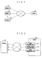
- FIG. 1 is a diagram showing the outline configuration of a multipoint conference system according to an embodiment of the present invention.
- Reference to FIG. 1 shows a multipoint conference system connecting n (hereinafter, n denotes an integer equal to or greater than 2) terminals 101 to 10n and a multipoint conference server (hereinafter, simply called a server) 200 via a network 500.
- n denotes an integer equal to or greater than 2
- a server hereinafter, simply called a server
- FIG. 2 is a diagram showing a connection between each terminal and the server 200 in the multipoint conference system.
- a terminal 101 shown in FIG. 2 performs communication with each of a video receiving part 210, a control signal receiving part 220, and a video transmitting part 290 of the server 200 via the network 500 to perform transmission and reception of video streams along with transmission and reception of predetermined control signals.
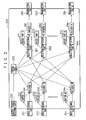
- FIG. 3 is a diagram showing a detailed configuration when n terminals are connected to the server 200 in the multipoint conference system.
- the server 200 can communicate with each of the terminals 101 to 10n by means of n video receiving parts 211 to 21n, n buffers 231 to 23n, n decoders 241 to 24n, n selection/composition parts 261 to 26n, n resize parts 271 to 27n, n encoders 281 to 28n, and n (video) transmitting part 291 to 29n in order to support n terminals.
- the control signal receiving part 220 is a means for receiving a control signal from the terminals 101 to 10n to convey the control signal to the control part 250 and the control part 250 is a means, in addition to control of the whole server 200, for giving instructions to each unit including the decoders 241 to 24n after determining video streams to be delivered to each of the terminals 101 to 10n based on control signals.
- the video receiving parts 211 to 21n are means for receiving packets including video streams from the terminals 101 to 10n via the network 500.
- the buffers 231 to 23n are temporary storage destinations of video streams stored in a memory of the server 200.
- the decoders 241 to 24n are means for decoding video streams to create images and, as described later, have a flag indicating whether or not a video stream received from each terminal is currently to be decoded by means of active/inactive.
- the selection/composition parts 261 to 26n are means for selecting an image output from the decoders 241 to 24n or a plurality of images for amalgamating them according to instructions from the control part 250.
- the resize parts 271 to 27n are means for scaling images output from the selection/composition parts 261 to 26n to the size fitting to each of the terminals 101 to 10n.
- the encoders 281 to 28n are means for encoding images in accordance with the encoding method, encoding settings, and parameters fitting to each of the terminals 101 to 10n to convert such images into a video stream.
- the (video) transmitting parts 291 to 29n are means for transmitting a video stream created by the encoders 281 to 28n to each of the matched terminals 101 to 10n via the network 500.
- the multipoint conference server 200 is equipped with various processing means for manipulating voice streams.
- the video receiving parts 211 to 21n of the server 200 each receive and analyze individually packets from each terminal to extract video streams.
- the buffers 231 to 23n are not used and the streams are individually decoded by the decoders 241 to 24n to create one to n images.
- the selection/composition parts 261 to 26n select/compose images according to instructions of the control part 250 and the encoders 281 to 28n perform encode processing for each terminal.
- a video stream created by encoding is packetized before being individually transmitted to the terminals 101 to 10n by the (video) transmitting parts 291 to 29n.
- the terminals 101 to 10n can switch the video stream received from the server 200 by transmitting a control signal to the control signal receiving part 220 of the server 200 to convey a request to the server 200.
- the flags of the decoders 241 to 24n are referenced.
- the flags of the decoders 241 to 24n are active (to be decoded)
- the video streams are decoded like the aforementioned case.
- the flags of the decoders 241 to 24n are inactive (not to be decoded)
- processing to temporarily store the video streams in the buffers 231 to 23n is performed.
- FIG. 4 is a flow chart showing operations of the decoders 241 to 24n when an activation instruction is received from the control part 250 in an inactive (not to be decoded) state. After receiving the activation instruction, the decoders 241 to 24n check whether or not any video stream is stored in the buffers 231 to 23n (step S001).
- the decoders 241 to 24n decode stored data (stream data) (step S003).
- an intra-frame an intra-frame coded frame; hereafter referred to as an I-frame
- decoding will start from the I-frame.
- a portion of data that has been decoded is deleted from the buffers and if data is still stored in the buffers 231 to 23n, the above steps S001 and S002 are repeated.
- the decoders 241 to 24n ignore time information and decode streams stored in the buffers 231 to 23n all at once.
- the latest image among a plurality of images generated by decoding is used by the selection/composition parts 261 to 26n.
- the decoders 241 to 24n make a transition to a decoding state in which the flag is set to active (to be decoded) (step S002).
- FIG. 5 is a flow chart showing operations of the decoders 241 to 24n when an inactivation instruction is received from the control part 250 in an active (to be decoded) state. After receiving the inactivation instruction, instead of immediately stopping decoding, the decoders 241 to 24n decide behavior based on data receives by the video receiving part.
- step S101 If the video stream of packets received in step S101 is not data of the I-frame (N step S102), the decoders 241 to 24n performs decoding like in the aforementioned active (to be decoded) state (step S103).
- the decoders 241 to 24n store the data in the buffers 231 to 23n without decoding the data (step S104).
- the decoders 241 to 24n check whether or not received data is the last data of the I-frame (step S105) and, if the stored data is not the last data of the I-frame, return to step S101 to receive divided subsequent data of the I-frame.
- the decoders 241 to 24n stop decode processing and makes a transition to a non-decoding state in which the flag is set to inactive (not to be decoded) (step S006).
- the buffers 231 to 23n are controlled in this manner so that data is always stored beginning with the start of an I-frame and, when I-frame data should be newly stored, previous data is deleted.
- FIG. 6 is a diagram for illustrating frame storage control in the buffers 231 to 23n realized by the aforementioned procedure.
- the terms 23x_T0 to 23x_T5 on the left side of FIG. 6 represent changes of the internal state of the same buffer 23x according to the flow of time (T0 to T5).
- the terms P_T0 to P_T4 on the right side of FIG. 6 represent video stream data arriving at each point in time.
- Ix (x is the arrival order) represents stream data of an I-frame and the term Px (x is the arrival order) represents stream data other than the I-frame.
- the buffer is empty in the 23x_T0 state of FIG. 6 and then the data P_T0, which is not an I-frame, arrives. Since a control operation is performed to first store an I-frame in the buffers 231 to 23n, the data P_T0 is discarded in this case.
- the buffer is empty in the 23x_T1 state of FIG. 6 like at the previous point in time and then, when the data P_T1, which is the I-frame, arrives, the data P_T1 is stored to enter the 23x_T2 state.
- the data P_T2 further arrives in the 23x_T2 state of FIG. 6
- the 1-frame data P_T1 is already stored and thus the data P_T2 is subsequently stored to enter the 23x_T3 state.
- the data P_T3 further arrives in the 23x_T3 state of FIG. 6
- similarly the data P_T3 is subsequently stored to enter the 23x_T4 state of FIG. 6 .
- the data P_T4 which is a new I-frame, arrives, all previous data is discarded and the data P_T4 is stored as the first data to enter the 23x_T5 state.
- FIG. 7 is a diagram for illustrating frame storage control when an I-frame divided into a plurality of packets arrives.
- the terms 23x_T10 to 23x_T13 on the left side of FIG. 7 represent changes of the internal state of the same buffer 23x according to the flow of time (T10 to T13).
- the terms P_T10 to P_T12 on the right side of FIG. 7 represent video stream data arriving at each point in time.
- Ixy (x is the arrival order and y is the division number) represents stream data of an I-frame and Px represents data other than the I-frame.
- the arriving data P1_T10 and P2_T10 in the 23x_T10 state of FIG. 7 is data (I2a, I2b) of the I-frame divided into two parts back and forth.
- the data P1_T10 in the first half is stored in the buffer and, in this stage, existing data is not discarded due to arrival of a new I-frame and the 23x_T11 state is entered.
- data P_T11 in the second half is further stored in the buffer in the 23x_T11 state of FIG. 7 , all data prior to the new I-frame data (I2a, I2b) is discarded to enter the 23x_T12 state.
- the operation after decoding by the decoders 241 to 24n is performed will be described again with reference to FIG. 3 .
- the selection/composition parts 261 to 26n acquire decoded images from the decoders 241 to 24n.
- the selection/composition parts 261 to 26n perform processing (composition processing) to compose a plurality of images horizontally and vertically. Further, if the size of an acquired or composed image and that of a video stream transmitted to the terminals 101 to 10n are different, the resize parts 271 to 27n perform scaling processing of the image based on instructions from the control part 250.
- the encoders 281 to 28n encode images fitting to bit rates and parameters of the transmission destination terminals 101 to 10n to convert images into a video stream.
- the (video) transmitting parts 291 to 29n packetize the converted video stream to transmit packets to the terminals 101 to 10n via the network 500.
- the multipoint conference system has the configuration capable of controlling an increase in computational complexity, it is possible to swiftly respond to a switching request of the video stream from the terminals. This is because unused stream data is stored in the buffers and held in a state so that the data stream can be decoded at any time.
- decoding is started with an I-frame by going back in time, inhibiting degradation of image quality.
- FIG. 8 is a diagram showing a detailed configuration of a server 300 of the multipoint conference system according to the second embodiment of the present invention.
- FIG. 8 shows that the server 300 can communicate, in addition to a DTMF (Dual Tone Multi-Frequency) receiving part 320 and a control part 350, n RTP (Real Time transport Protocol) receiving parts 311 to 31n, n buffers 331 to 33n, n MPEG-4 decoders 341 to 34n, n selection/composition parts 361 to 36n, n resize parts 371 to 37n, n MPEG-4 encoders 381 to 38n, and n RTP transmitting parts 391 to 39n in order to support n terminals.
- DTMF Dual Tone Multi-Frequency
- n RTP Real Time transport Protocol
- the DTMF receiving part 320 is a means corresponding to the control signal receiving part 220 in the first embodiment and a means for receiving a DTMF signal from each terminal and conveying the DTMF signal to the control part 350.
- the control part 350 is a means, in addition to control of the whole server 300, for determining MPEG-4 streams to be delivered to each terminal based on the DTMF signal and giving instructions to each unit including the MPEG-4 decoders 341 to 34n.
- the RTP receiving parts 311 to 31n are means corresponding to the video receiving parts 211 to 21n in the first embodiment and means for receiving/analyzing RTP packets including MPEG-4 streams from terminals via the network 500 to extract the MPEG-4 streams.
- the buffers 331 to 33n are temporary storage destinations of video streams in a memory of the server 300.
- the MPEG-4 decoders 341 to 34n are means corresponding to the decoders 241 to 24n in the first embodiment and means for decoding video streams to create images. Like the aforementioned first embodiment, the MPEG-4 decoders 341 to 34n have a flag indicating whether or not a video stream received from each terminal is currently to be decoded by means of active/inactive.
- the selection/composition parts 361 to 36n are means for selecting, according to instructions from the control part 350, an image output from the MPEG-4 decoders 341 to 34n or a plurality of images from the MPEG-4 decoders 341 to 34n for composition into a state in which images are laid out vertically and horizontally.
- the resize parts 371 to 37n are means for scaling images output from the selection/composition parts 361 to 36n to the size fitting to each terminal.
- the MPEG-4 encoders 381 to 38n are means corresponding to the encoders 281 to 28n in the first embodiment and are means for encoding images in accordance with the encoding method, encoding settings, and parameters fitting to each terminal to convert such images into an MPEG-4 stream.
- the RTP transmitting parts 391 to 39n are means corresponding to the (video) transmitting part 291 to 29n in the first embodiment and are means for RTP-packetizing an MPEG-4 stream created by the MPEG-4 encoders 381 to 38n to transmit packets to each of the matched terminals 101 to 10n via the network 500.
- the multipoint conference server 300 is equipped with various processing means for manipulating voice streams.
- each terminal transmits an MPEG-4 stream as RTP packets to the server 300
- the RTP receiving parts 311 to 31n of the server 300 each receive and analyze individually packets from each terminal to extract MPEG-4 streams.
- the MPEG-4 decoders 341 to 34n changes their operation depending on whether or not the held flag is active, as shown below.
- the MPEG-4 decoders 341 to 34n in the active state decode MPEG-4 streams to create images transmitted from each terminal.
- the MPEG-4 decoders 341 to 34n continue decode processing until an I-frame arrives and, after the I-frame arrives, rewrite the flag to make a transition to the non-decoding state.
- the MPEG-4 decoders 341 to 34n After making a transition to the non-decoding state, the MPEG-4 decoders 341 to 34n store MPEG-4 stream data in the 1-frame that has arrived in the buffers 331 to 33n. Like the aforementioned first embodiment, content of the buffers 331 to 33n is retained until a whole new I-frame arrives (If the I-frame is divided, the last data is awaited) and is cleared when the new I-frame arrives.
- the MPEG-4 decoders 341 to 34n decode content by going back to the latest frame (I-frame) accumulated in the buffers.
- the MPEG-4 encoders 381 to 38n perform encode processing for each terminal.
- An MPEG-4 stream created by encoding is RTP-packetized by the RTP transmitting parts 391 to 39n before being individually transmitted to the terminals.
- the terminals can also switch the video received from the server 300 by transmitting a control signal as a DTMF signal to the DTMF receiving part 320 of the server 300 to convey a request to the server 300.
- each of the above embodiments was described assuming that the server holds data after the latest I-frame in its buffer and, when a switching request is made, decodes from the start of the buffer (that is, the latest I-frame).
- the present invention can naturally be carried out in various modification and replacements without departing the spirit of the present invention, namely as far as video streams are stored in the buffer and, when a switching request is made, decoding is performed by going back a predetermined time to the past. For example, apart from the update logic of the buffer, read logic of the buffer (I-frame search) may naturally be provided.
Landscapes
- Engineering & Computer Science (AREA)
- Multimedia (AREA)
- Signal Processing (AREA)
- Two-Way Televisions, Distribution Of Moving Picture Or The Like (AREA)
- Telephonic Communication Services (AREA)
- Compression Or Coding Systems Of Tv Signals (AREA)
Applications Claiming Priority (2)
| Application Number | Priority Date | Filing Date | Title |
|---|---|---|---|
| JP2005202965 | 2005-07-12 | ||
| PCT/JP2006/311549 WO2007007496A1 (ja) | 2005-07-12 | 2006-06-08 | 多地点会議システム、多地点会議方法及びプログラム |
Publications (2)
| Publication Number | Publication Date |
|---|---|
| EP1909497A1 true EP1909497A1 (de) | 2008-04-09 |
| EP1909497A4 EP1909497A4 (de) | 2013-10-30 |
Family
ID=37636895
Family Applications (1)
| Application Number | Title | Priority Date | Filing Date |
|---|---|---|---|
| EP06766511.7A Withdrawn EP1909497A4 (de) | 2005-07-12 | 2006-06-08 | Mehrpunkt-konferenzsystem, mehrpunkt-konferenzverfahren und programm |
Country Status (8)
| Country | Link |
|---|---|
| US (1) | US8253775B2 (de) |
| EP (1) | EP1909497A4 (de) |
| JP (1) | JP4952581B2 (de) |
| KR (1) | KR100953457B1 (de) |
| CN (1) | CN101258748B (de) |
| BR (1) | BRPI0615511A2 (de) |
| RU (1) | RU2008105035A (de) |
| WO (1) | WO2007007496A1 (de) |
Families Citing this family (17)
| Publication number | Priority date | Publication date | Assignee | Title |
|---|---|---|---|---|
| US20080109557A1 (en) * | 2006-11-02 | 2008-05-08 | Vinay Joshi | Method and system for reducing switching delays between digital video feeds using personalized unicast transmission techniques |
| CN101647276A (zh) * | 2007-04-04 | 2010-02-10 | 日本电气株式会社 | 内容递送系统、内容递送方法及其中使用的转换装置 |
| US20100261454A1 (en) * | 2009-04-14 | 2010-10-14 | Research In Motion Limited | Retrieving additional content based on data within a mobile code |
| GB0916765D0 (en) * | 2009-09-24 | 2009-11-04 | Powers David A | Mosaic - web based audio and video stream regulation process |
| KR101234495B1 (ko) * | 2009-10-19 | 2013-02-18 | 한국전자통신연구원 | 화상회의 시스템을 위한 단말, 중계 노드 및 스트림 처리 방법 |
| KR101583088B1 (ko) * | 2009-11-11 | 2016-01-07 | 엘지전자 주식회사 | 화상 회의 시스템에서 데이터를 공유하는 방법 및 장치 |
| CN102131071B (zh) * | 2010-01-18 | 2013-04-24 | 华为终端有限公司 | 视频画面切换的方法和装置 |
| CN102695036B (zh) * | 2011-03-25 | 2015-01-21 | 鸿富锦精密工业(深圳)有限公司 | 视讯会议系统及其使用方法 |
| US9787738B2 (en) | 2012-06-19 | 2017-10-10 | Circle Technology, Inc. | Closed network video presentation |
| US8898449B2 (en) | 2012-06-19 | 2014-11-25 | Circle Technology, Inc. | Closed network presentation |
| US9167040B2 (en) | 2012-06-19 | 2015-10-20 | Circle Technology, Inc. | Closed network presentation with external router |
| KR101220948B1 (ko) * | 2012-09-11 | 2013-01-11 | (주)리얼허브 | 화상 회의 시스템을 위한 매트릭스 형태의 화면 출력 방법 |
| JP5908419B2 (ja) * | 2013-02-08 | 2016-04-26 | 日本電信電話株式会社 | 遠隔映像配信方法及び遠隔映像配信システム |
| CN104581200B (zh) * | 2015-02-06 | 2018-01-02 | 网易传媒科技(北京)有限公司 | 切片转码的方法和设备 |
| CN106850649A (zh) * | 2017-02-21 | 2017-06-13 | 杭州迈可行通信股份有限公司 | 一种视频会议终端的实现方法 |
| CN107277430A (zh) * | 2017-07-27 | 2017-10-20 | 福建星网智慧科技股份有限公司 | 一种视频会议系统的视频流轮播方法 |
| CN111901680B (zh) * | 2020-05-10 | 2022-06-21 | 天地阳光通信科技(北京)有限公司 | 多媒体数据处理方法、装置及服务器 |
Family Cites Families (28)
| Publication number | Priority date | Publication date | Assignee | Title |
|---|---|---|---|---|
| JPS61263385A (ja) * | 1985-05-17 | 1986-11-21 | Fujitsu Ltd | マルチポイントテレビ信号伝送方式 |
| JPH02125588A (ja) * | 1988-11-04 | 1990-05-14 | Nippon Telegr & Teleph Corp <Ntt> | 多地点画像表示装置 |
| JPH05328344A (ja) * | 1992-05-27 | 1993-12-10 | Mitsubishi Electric Corp | 映像交換分配システム |
| US5390177A (en) * | 1993-03-24 | 1995-02-14 | At&T Corp. | Conferencing arrangement for compressed information signals |
| JP2550860B2 (ja) * | 1993-06-15 | 1996-11-06 | 日本電気株式会社 | 画像復号化装置 |
| US5440336A (en) * | 1993-07-23 | 1995-08-08 | Electronic Data Systems Corporation | System and method for storing and forwarding audio and/or visual information on demand |
| JP3404808B2 (ja) * | 1993-07-30 | 2003-05-12 | ソニー株式会社 | 復号方法と復号装置 |
| JPH07264580A (ja) * | 1994-03-17 | 1995-10-13 | Toshiba Corp | 映像信号伝送方法並びに映像信号送信装置及び映像信号受信装置 |
| JPH07298257A (ja) * | 1994-04-25 | 1995-11-10 | Sony Corp | 画像データの伝送方法及び復号化装置 |
| US5495291A (en) * | 1994-07-22 | 1996-02-27 | Hewlett-Packard Company | Decompression system for compressed video data for providing uninterrupted decompressed video data output |
| JPH08107553A (ja) * | 1994-10-04 | 1996-04-23 | Canon Inc | 画像処理装置およびその方法 |
| JP2820630B2 (ja) * | 1994-12-07 | 1998-11-05 | 株式会社グラフィックス・コミュニケーション・ラボラトリーズ | 画像復号装置 |
| EP0783817B1 (de) * | 1995-07-19 | 2000-05-10 | Koninklijke Philips Electronics N.V. | Verfahren und vorrichtung zur dekodierung von digitalen videobitdaten und empfängervorrichtung dafür |
| JPH09219851A (ja) * | 1996-02-09 | 1997-08-19 | Nec Corp | 多地点ビデオ会議制御方法及び装置 |
| JP3469705B2 (ja) * | 1996-03-12 | 2003-11-25 | 三洋電機株式会社 | 多重映像信号の復号回路 |
| JP3097736B2 (ja) | 1996-11-29 | 2000-10-10 | 日本電気株式会社 | 多画面伝送式多地点テレビ会議システム |
| JP2000078552A (ja) * | 1998-09-02 | 2000-03-14 | Nec Corp | テレビ会議システム |
| JP2000174909A (ja) * | 1998-12-08 | 2000-06-23 | Nec Corp | 会議端末制御装置 |
| JP2001045495A (ja) * | 1999-08-02 | 2001-02-16 | Nec Eng Ltd | 画面合成装置 |
| EP1323308B1 (de) * | 2000-08-15 | 2014-08-20 | Polycom Israel Ltd. | Verzögerungsreduktion zur übertragung und verarbeitung von videodaten |
| US7266091B2 (en) * | 2001-02-28 | 2007-09-04 | The Trustees Of Columbia University In City Of New York | System and method for conferencing in inter/intranet telephony |
| JP2002290940A (ja) | 2001-03-23 | 2002-10-04 | Nec Eng Ltd | テレビ会議システム |
| JP3788260B2 (ja) * | 2001-04-09 | 2006-06-21 | 日本電気株式会社 | 配信システムとその配信方法、及び配信プログラム |
| CN1422078A (zh) * | 2001-11-22 | 2003-06-04 | 丽台科技股份有限公司 | 视频会议系统 |
| AU2002329160A1 (en) | 2002-08-13 | 2004-02-25 | Nanyang Technological University | Method of increasing speech intelligibility and device therefor |
| KR100463876B1 (ko) | 2003-02-07 | 2005-01-03 | 주식회사 시스캠퍼스 | 화상회의 제어 방법 |
| RU2240657C1 (ru) | 2003-12-29 | 2004-11-20 | Дмитриев Григорий Гемфриевич | Способ и система осуществления видеоконференций |
| JP2005244898A (ja) * | 2004-02-27 | 2005-09-08 | Fujitsu Ltd | ビデオ符号化データ合成装置 |
-
2006
- 2006-06-08 BR BRPI0615511-1A patent/BRPI0615511A2/pt not_active IP Right Cessation
- 2006-06-08 RU RU2008105035/09A patent/RU2008105035A/ru not_active Application Discontinuation
- 2006-06-08 US US11/993,934 patent/US8253775B2/en not_active Expired - Fee Related
- 2006-06-08 WO PCT/JP2006/311549 patent/WO2007007496A1/ja not_active Ceased
- 2006-06-08 KR KR1020087000943A patent/KR100953457B1/ko not_active Expired - Fee Related
- 2006-06-08 CN CN2006800252542A patent/CN101258748B/zh not_active Expired - Fee Related
- 2006-06-08 JP JP2007524545A patent/JP4952581B2/ja not_active Expired - Fee Related
- 2006-06-08 EP EP06766511.7A patent/EP1909497A4/de not_active Withdrawn
Also Published As
| Publication number | Publication date |
|---|---|
| US20090207232A1 (en) | 2009-08-20 |
| RU2008105035A (ru) | 2009-08-20 |
| KR20080017096A (ko) | 2008-02-25 |
| CN101258748B (zh) | 2010-12-08 |
| WO2007007496A1 (ja) | 2007-01-18 |
| JP4952581B2 (ja) | 2012-06-13 |
| EP1909497A4 (de) | 2013-10-30 |
| KR100953457B1 (ko) | 2010-04-19 |
| CN101258748A (zh) | 2008-09-03 |
| JPWO2007007496A1 (ja) | 2009-01-29 |
| US8253775B2 (en) | 2012-08-28 |
| BRPI0615511A2 (pt) | 2011-05-17 |
Similar Documents
| Publication | Publication Date | Title |
|---|---|---|
| US11956472B2 (en) | Video data stream concept | |
| EP1909497A1 (de) | Mehrpunkt-konferenzsystem, mehrpunkt-konferenzverfahren und programm | |
| EP1815684B1 (de) | Verfahren und vorrichtung zum kanalwechseln in dsl system | |
| MX2008000117A (es) | Sistema de conferencia de multipunto, metodo de conferencia de multipunto, y programa. | |
| HK40018301B (en) | Video data stream, encoder, method for encoding video content and decoder |
Legal Events
| Date | Code | Title | Description |
|---|---|---|---|
| PUAI | Public reference made under article 153(3) epc to a published international application that has entered the european phase |
Free format text: ORIGINAL CODE: 0009012 |
|
| 17P | Request for examination filed |
Effective date: 20071220 |
|
| AK | Designated contracting states |
Kind code of ref document: A1 Designated state(s): DE FR GB |
|
| RBV | Designated contracting states (corrected) |
Designated state(s): DE FR GB |
|
| RBV | Designated contracting states (corrected) |
Designated state(s): DE FR GB |
|
| DAX | Request for extension of the european patent (deleted) | ||
| A4 | Supplementary search report drawn up and despatched |
Effective date: 20130926 |
|
| RIC1 | Information provided on ipc code assigned before grant |
Ipc: H04N 7/15 20060101AFI20130920BHEP Ipc: H04M 3/56 20060101ALI20130920BHEP |
|
| STAA | Information on the status of an ep patent application or granted ep patent |
Free format text: STATUS: THE APPLICATION HAS BEEN WITHDRAWN |
|
| 18W | Application withdrawn |
Effective date: 20140429 |