EP1910665B1 - Dispositif d'injection de carburant pour moteur a combustion interne - Google Patents
Dispositif d'injection de carburant pour moteur a combustion interne Download PDFInfo
- Publication number
- EP1910665B1 EP1910665B1 EP06794480A EP06794480A EP1910665B1 EP 1910665 B1 EP1910665 B1 EP 1910665B1 EP 06794480 A EP06794480 A EP 06794480A EP 06794480 A EP06794480 A EP 06794480A EP 1910665 B1 EP1910665 B1 EP 1910665B1
- Authority
- EP
- European Patent Office
- Prior art keywords
- injection
- needle
- fuel
- injection device
- piezoelectric
- Prior art date
- Legal status (The legal status is an assumption and is not a legal conclusion. Google has not performed a legal analysis and makes no representation as to the accuracy of the status listed.)
- Not-in-force
Links
- 238000002347 injection Methods 0.000 title claims abstract description 92
- 239000007924 injection Substances 0.000 title claims abstract description 92
- 239000000446 fuel Substances 0.000 title claims abstract description 74
- 238000002485 combustion reaction Methods 0.000 title claims abstract description 8
- 230000005284 excitation Effects 0.000 claims description 18
- 238000013016 damping Methods 0.000 claims description 11
- 238000006073 displacement reaction Methods 0.000 description 14
- 230000010355 oscillation Effects 0.000 description 14
- 230000000694 effects Effects 0.000 description 4
- 239000000919 ceramic Substances 0.000 description 3
- 238000005194 fractionation Methods 0.000 description 3
- 239000000463 material Substances 0.000 description 3
- 239000007921 spray Substances 0.000 description 2
- 238000005507 spraying Methods 0.000 description 2
- 229910001329 Terfenol-D Inorganic materials 0.000 description 1
- 230000015572 biosynthetic process Effects 0.000 description 1
- 230000006835 compression Effects 0.000 description 1
- 238000007906 compression Methods 0.000 description 1
- 230000003247 decreasing effect Effects 0.000 description 1
- 239000003344 environmental pollutant Substances 0.000 description 1
- 239000012530 fluid Substances 0.000 description 1
- 239000002828 fuel tank Substances 0.000 description 1
- 239000007789 gas Substances 0.000 description 1
- 239000003502 gasoline Substances 0.000 description 1
- 239000000203 mixture Substances 0.000 description 1
- 230000003534 oscillatory effect Effects 0.000 description 1
- 239000002245 particle Substances 0.000 description 1
- 231100000719 pollutant Toxicity 0.000 description 1
- 239000004071 soot Substances 0.000 description 1
- 238000004544 sputter deposition Methods 0.000 description 1
- 238000002604 ultrasonography Methods 0.000 description 1
Images


Classifications
-
- F—MECHANICAL ENGINEERING; LIGHTING; HEATING; WEAPONS; BLASTING
- F02—COMBUSTION ENGINES; HOT-GAS OR COMBUSTION-PRODUCT ENGINE PLANTS
- F02M—SUPPLYING COMBUSTION ENGINES IN GENERAL WITH COMBUSTIBLE MIXTURES OR CONSTITUENTS THEREOF
- F02M51/00—Fuel-injection apparatus characterised by being operated electrically
- F02M51/06—Injectors peculiar thereto with means directly operating the valve needle
- F02M51/0603—Injectors peculiar thereto with means directly operating the valve needle using piezoelectric or magnetostrictive operating means
-
- F—MECHANICAL ENGINEERING; LIGHTING; HEATING; WEAPONS; BLASTING
- F02—COMBUSTION ENGINES; HOT-GAS OR COMBUSTION-PRODUCT ENGINE PLANTS
- F02M—SUPPLYING COMBUSTION ENGINES IN GENERAL WITH COMBUSTIBLE MIXTURES OR CONSTITUENTS THEREOF
- F02M45/00—Fuel-injection apparatus characterised by having a cyclic delivery of specific time/pressure or time/quantity relationship
- F02M45/02—Fuel-injection apparatus characterised by having a cyclic delivery of specific time/pressure or time/quantity relationship with each cyclic delivery being separated into two or more parts
- F02M45/10—Other injectors with multiple-part delivery, e.g. with vibrating valves
-
- F—MECHANICAL ENGINEERING; LIGHTING; HEATING; WEAPONS; BLASTING
- F02—COMBUSTION ENGINES; HOT-GAS OR COMBUSTION-PRODUCT ENGINE PLANTS
- F02M—SUPPLYING COMBUSTION ENGINES IN GENERAL WITH COMBUSTIBLE MIXTURES OR CONSTITUENTS THEREOF
- F02M69/00—Low-pressure fuel-injection apparatus ; Apparatus with both continuous and intermittent injection; Apparatus injecting different types of fuel
- F02M69/04—Injectors peculiar thereto
- F02M69/041—Injectors peculiar thereto having vibrating means for atomizing the fuel, e.g. with sonic or ultrasonic vibrations
Definitions
- the present invention is part of fuel injection devices for internal combustion engines, to provide very finely atomized fuel ( WO-A-01/36813 ).
- the spray fuel injection devices generally comprise a variable frequency ultrasonic actuator, a frequency variation control for controlling the displacement movement of the needle by translation.
- the ultrasonic frequency and the excitation amplitude of the actuator can be slaved to the pressure of the gases in the combustion chamber or to other parameters, which makes it possible to make the flow rate of the backpressure develops after the onset of combustion.
- Injection devices of this type can be used for diesel direct injection or prechamber engines, for homogeneous charge compression ignition engines (HCCI) or for direct or indirect injection gasoline engines. .
- HCCI charge compression ignition engines
- direct or indirect injection gasoline engines HCCI
- the purpose of the precise control of the excitation frequency of the actuator is to reduce pollutant emissions, fuel consumption and the appearance of soot particles.
- Injection devices of this type must also facilitate the operation of the combustion engine lean or stratified mixture.
- such a fuel injection device which comprises, in an injection box fed with fuel at high pressure, a movable needle in translation which can be driven by high frequency oscillations under the action of a vibratory element ultrasonic piezoelectric device comprising a stack of piezoelectric ceramic rings.
- This stack is installed inside the injection box and can print, when excited, a vibratory movement of alternating oscillations to a cylindrical body integral with the injection needle.
- the injection head located at the end of the needle cooperates with a seat to determine a fuel injection passage whose opening, and therefore the fuel flow, is defined by the oscillatory movement of the head of the fuel. injection.
- Such a piezoelectric control element may also be replaced by an ultrasonic magnetostrictive element using a bar of terfenol D magnetostrictive material or any other material having equivalent properties.
- the excitation imparted by the vibratory element to the needle generates oscillations of the needle which can be amplified when the latter is suitably tuned, for example in a quarter-wave.
- the present invention aims to solve these difficulties by producing a fuel injection device for better control of the injected fuel flow, and insensitivity of the flow to the effects of thermal expansion.
- the invention also relates to such an injection device that facilitates cold starts, that is to say the injection of more viscous fuel than during normal operation of the engine.
- the fuel injection device for an internal combustion engine is of the type comprising an injection head integral with the end of a movable needle in translation inside a housing of injection fueled with high pressure fuel.
- the housing has a seat for the injection head.
- a piezoelectric or magnetostrictive vibrating element is able, when excited, to act on the needle, held by a return spring, to put it into vibration.
- the injection head cooperates with its seat to periodically open and close a fuel injection passage.
- the device also comprises a means for controlling the displacement of the needle by translation, which is independent of the control of the vibratory element.
- the movement of the needle, which allows to define the injected fuel flow is controlled independently of the excitation of the vibratory element which ensures in turn the high frequency fractionation of the fuel ply performing the spraying of the fuel injected.
- the excitation frequency of the vibratory element for the fractionation of the injected fuel ply can be variable and it is no longer necessary to optimize it to obtain a specific needle displacement since the displacement of needle is controlled by another means.
- the control of the spraying by the high-frequency oscillations of the needle can further be initiated even before the control of movement of the needle and stopped afterwards.
- the high frequency ultrasonic control spray can be easily adapted to the temperature of the fuel to be injected by acting on the oscillation frequency. A cold start with a more viscous fuel becomes easier to manage.
- the needle displacement control means comprises a piezoelectric or magnetostrictive element that can be energized independently of the vibratory element that generates the oscillations of the needle.
- the needle may advantageously be mounted at the end of a generally cylindrical body part of an assembly movable in translation inside the injection housing.
- the piezoelectric or magnetostrictive vibratory element which generates the oscillations of the needle and the splitting of the injected fuel ply is an integral part of this moving assembly, which comprises also a damping mass adapted to define the resonant frequency of the assembly.
- the piezoelectric or magnetostrictive element of the translational needle displacement control means is integral with the moving assembly.
- the movable assembly includes a piston portion movable in a hydraulic control chamber fed with fuel under high pressure.
- the control chamber communicates with the low pressure fuel return through a discharge valve actuated by the control means.
- the opening of the fuel injection passage may be caused by an exit movement of the injection head relative to the injection housing.
- the excitation of the piezoelectric or magnetostrictive element of the control means causes a closing action of the discharge valve.
- the opening of the fuel injection passage is caused by a re-entry movement of the injection head with respect to the injection box.
- the excitation of the piezoelectric or magnetostrictive element of the control means causes an opening action of the discharge valve.
- the needle is generally integral with a shoulder of the cylindrical body, capable of sliding in a housing of the injection housing ensuring a very low fluid leakage.
- a flow limiter is thus defined for the pressurized fuel that escapes inside the injection box to a return line.
- Fuel supply pipes with high pressure and low pressure fuel return are advantageously provided in the injection box, for example in the wall thickness of the housing.
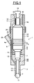
- the fuel injection device As represented on the figure 1 , the fuel injection device, referenced 1 as a whole, comprises an injection head 2 secured to the end of a needle 3 movable in translation inside an injection housing 4.
- a component Piezoelectric vibratory device 5 comprises a stack of four ceramic rings 6 made of piezoelectric material.
- the needle 3 is integral with a shoulder 7, which extends in the direction of the needle 3 a cylindrical body 8 whose diameter is adapted to the internal cavity of the injection housing 4, so as to leave a gap between the cylindrical body 8 mounted inside a chamber 9 and the wall of the housing 4.
- a return spring 10 acts on the cylindrical body 8, so as to move it in the direction which plate the injection head 2 on its seat 11, that is to say closes the passage for the fuel injection.
- the fuel is introduced under high pressure through a feed pipe 12 which passes longitudinally through the wall of the housing 4 and which ends in a space 13 remaining between the needle 3 and a guide 14 at the end of which is defined the seat 11.
- the stack of piezoelectric ceramics 6 which defines the vibratory element 5.
- a damping mass 15 which has a general shape cylindrical of the same diameter as the cylindrical body 8 and the different piezoelectric rings 6.
- the assembly constituted by the needle 3, the shoulder 7, the cylindrical body 8, the vibratory element 5 and the damping mass 15 constitutes a movable assembly 4a in translation inside the injection box 4.
- a magnetostrictive bar 16 which constitutes a means for controlling the displacement of the assembly 4a and therefore of the needle 3.
- the bar 16 is mounted inside an excitation solenoid 17.
- the magnetostrictive bar 16 is furthermore secured to a locking element 18 which ensures its fixing in the injection box 4.
- the housing 4 is in several parts.
- the housing 4 has in fact a central portion 18 defining the chamber 9 inside which can move the assembly 4a comprising the cylindrical body 8, the vibratory element 5 and the damping mass 15.
- the upper cap 19 has a central housing 21 which receives the solenoid 17 and the magnetostrictive bar 16.
- the wall of the upper cap 19 is pierced by a conduit 22 which is in communication with the chamber 9 and allows the return of the non-injected fuel at low pressure.
- the housing 4 is completed by a lower part 23 which has a central housing 24, inside which can move in translation the shoulder 7.
- the housing 24 defines a means of flow rate limitation for the uninjected fuel which can escape upwards in the clearance remaining between the shoulder 7 and the housing 24, then passing through the chamber 9 to the return line 22.
- the feed pipe 12 of the pressurized fuel has an inlet portion 25 made in a lateral block 26 integral with the central portion 18 of the injection box 4.
- the pressurized fuel is supplied by the pipe 12.
- the piezoelectric elements 6 are supplied with electric current by means not shown in the figure, at high ultrasound frequency, so as to cause high frequency oscillations of the needle. 3 and the injection head 2.
- the injection head 2 is here made in the form of a ball of which about half comes out of its seat 11.
- the head can have another shape .
- the very high frequency oscillations of the head 2 allow splitting of the injected fuel layer, which is therefore sprayed in the form of very fine droplets.
- the supply of electrical current to the excitation solenoid 17 causes the formation of a magnetic field inside said solenoid, and thereby an elongation of the bar 16 by magnetostrictive effect.
- This extension causes a downward thrust on the assembly 4a formed by the damping mass 15, the vibratory element 5, the cylindrical body 8, the shoulder 7 and the needle 3. This translational movement downward away the head 2 of its seat 11 and increases the flow of fuel injected.
- the excitation of the piezoelectric elements 6 generates oscillations of the needle 3 which can be amplified by appropriately matching the different parts, for example quarter-wave, taking into account the resonant frequency of the needle 3 , the shoulder 7, the cylindrical body 8 and the damping mass 15.
- the displacement of the needle is obtained by the magnetostrictive rod only 16, while the fractionation of the fuel ply causing the sputtering of the injected fuel can be optimized by separate excitation.
- FIG. figure 2 differs from the embodiment illustrated in FIG. figure 1 by the mode of action of the magnetostrictive bar 16.
- a cylindrical piston portion 27 is mounted at the upper end of the damping mass 15.
- the piston 27 is movable in a hydraulic control chamber 28 which is supplied with pressurized fuel by a bypass 29 connected to the pipe 25 pressurized fuel supply.
- the magnetostrictive bar 16 and the excitation solenoid 17 are therefore not, as in the embodiment illustrated in FIG. figure 1 secured to the movable assembly 4a comprising the needle 3.
- the lower end 30 of the bar 16 has a conical shaped part which can cooperate with an equally conical seat 31 formed in the upper cap 19 and defining a passage for the pressurized fuel in the control chamber 28.
- the assembly comprising the end 30 and the seat 31 therefore constitutes a discharge valve 30a for the fuel.
- the discharge valve 30a When the discharge valve 30a is open, the pressurized fuel can enter the chamber 21 and then, through a pipe 32 communicating with the return line 22, be brought back into the fuel tank at low pressure.
- An excitation of the magnetostrictive bar 16 by the solenoid 17 can, as in the previous embodiment, cause an expansion of the magnetostrictive bar 16 causing a downward movement of the conical end 30, which tends to close the discharge valve 30a by decreasing the leakage passage for the pressurized fuel in the control chamber 28.
- the fuel injection passage is therefore increased by the descent of the injection head 2.
- the stack of piezoelectric rings 6 constituting the vibratory element 5 can be supplied with electric current at a very high frequency, which makes it possible to animate the needle 3 and the injection head 2 a reciprocating movement at very high frequency, closing and periodically opening the arrival of the fuel which is fractionated into very fine droplets.
- the rod 16 retracts, which opens the discharge valve 30a and increases the leakage passage between the end 30 and its seat 31. The fuel can then escape more easily.
- the hydraulic control chamber 28 to join the return pipe 22 at low pressure.
- the piston 27 being subjected to a lower pressure, can no longer oppose the upward force exerted by the return spring 10, so that the needle 3 is raised and the injection head 2 comes close the injection passage.
- the vibratory actuator can be achieved using a magnetostrictive element.
- the injection head 2 is of the "outgoing" type. It is by a translational movement downwards in the figures, of the needle 3, that it is possible to increase the flow rate of the fuel injected.
- the embodiment illustrated on the figure 3 shows on the contrary a needle of the type "reentrant".
- the needle 3 has indeed a conical end 33 which cooperates with the seat 11, here made in conical form. In this embodiment, it is a translation movement upwards, on the figure 3 , the needle 3, which increases the opening of the injection passage.
- the return spring 10 is here mounted to the upper part of the damping mass 15 and exerts a downward force, tending to lower the needle 3 and to close the fuel injection passage.
- the control of the displacement of the needle is made by hydraulic means, as in the embodiment of the figure 2 .
- the piston piece 27 movable inside the hydraulic control chamber 28.
- the control movement of the needle 3 must however be reversed, the discharge valve 30a is here reversed by compared to that used in the embodiment illustrated on the figure 2 .
- the magnetostrictive rod 16 is secured, by its lower end, to a frustoconical piece 34 against which a spring returns to act, which is also supported on the upper face of the piston 27.
- the return spring 35 is housed in the hydraulic control chamber 28.
- the magnetostrictive bar 16 expands and moves its conical end 34 downwards, which has the effect of opening the passage defined by the discharge valve 30a by moving the piece away. frustoconical 34 of its seat 31.
- the return spring 10 must be chosen so as to allow this upward movement of the moving assembly 4a comprising the piston 27, the needle 3 and the other elements intercalated, during a decrease in the hydraulic pressure in the control chamber 28.
- the return spring 35 allows him to stabilize the operation of the assembly, but can optionally be removed.
Landscapes
- Engineering & Computer Science (AREA)
- Chemical & Material Sciences (AREA)
- Combustion & Propulsion (AREA)
- Mechanical Engineering (AREA)
- General Engineering & Computer Science (AREA)
- Fuel-Injection Apparatus (AREA)
Description
- La présente invention s'inscrit dans le cadre des dispositifs d'injection de carburant pour moteurs à combustion interne, permettant de fournir du carburant très finement pulvérisé (
WO-A-01/36813 - On peut utiliser des dispositifs d'injection de ce type pour des moteurs de type Diesel à injection directe ou à préchambre, pour des moteurs à allumage par compression à charge homogène (dits HCCI) ou également pour des moteurs à essence à injection directe ou indirecte. Dans tous les cas, le but recherché par la commande précise de la fréquence d'excitation de l'actionneur est de réduire les émissions polluantes, la consommation de carburant et l'apparition de particules de suies. Les dispositifs d'injection de ce type doivent également faciliter le fonctionnement du moteur à combustion en mélange pauvre ou stratifié.
- On connaît par exemple, par la demande de brevet
2 807 008 - Un tel élément de commande piézoélectrique peut également être remplacé par un élément magnétostrictif ultrasonore utilisant un barreau de matière magnétostrictive de type Terfenol D ou toute autre matière ayant des propriétés équivalentes.
- Dans les deux cas, l'excitation imprimée par l'élément vibratoire à l'aiguille engendre des oscillations de l'aiguille qui peuvent être amplifiées lorsque cette dernière est convenablement accordée, par exemple en quart d'onde.
- On constate cependant qu'un tel dispositif d'injection présente différents inconvénients. En effet, il est nécessaire de maîtriser parfaitement les oscillations de la tête d'injection ainsi que les différents effets de résonance de façon à contrôler avec précision le débit de carburant injecté. Tout frottement de l'aiguille d'injection dans son alésage à l'intérieur du dispositif d'injection, ou de la tête dans la culasse entraîne un impact significatif sur le débit du carburant injecté. De même, un désaccord de la fréquence de résonance entraîne une modification de la position du noeud de déplacement lors des oscillations de l'aiguille, ce qui modifie le débit du carburant injecté. On constate, dans la pratique, qu'il est difficile de maîtriser parfaitement ces différents paramètres et de réaliser des dispositifs d'injection dont les performances soient identiques et ne varient pas dans le temps.
- La présente invention a pour objet de résoudre ces difficultés par la réalisation d'un dispositif d'injection de carburant permettant un meilleur contrôle du débit de carburant injecté, ainsi qu'une insensibilité du débit aux effets des dilatations thermiques. L'invention a également pour objet un tel dispositif d'injection qui permette de faciliter les démarrages à froid, c'est-à-dire l'injection de carburant plus visqueux qu'au cours du fonctionnement normal du moteur thermique.
- Dans un mode de réalisation, le dispositif d'injection de carburant pour moteur à combustion interne, est du type comprenant une tête d'injection solidaire de l'extrémité d'une aiguille mobile en translation à l'intérieur d'un boîtier d'injection alimenté en carburant à haute pression. Le boîtier présente un siège pour la tête d'injection. Un élément vibratoire piézoélectrique ou magnétostrictif est capable, lorsqu'il est excité, d'agir sur l'aiguille, maintenue par un ressort de rappel, pour la mettre en vibration. De cette manière, la tête d'injection coopère avec son siège pour ouvrir et fermer périodiquement un passage d'injection du carburant. Le dispositif comprend également un moyen de commande de déplacement de l'aiguille par translation, qui est indépendant de la commande de l'élément vibratoire.
- Le déplacement de l'aiguille, qui permet de définir le débit de carburant injecté est commandé indépendamment de l'excitation de l'élément vibratoire qui assure quant à lui le fractionnement à haute fréquence de la nappe de carburant réalisant la pulvérisation du carburant injecté.
- En commandant ainsi le déplacement de l'aiguille indépendamment de l'excitation de fractionnement, on obtient un débit de carburant plus précis et mieux contrôlé. La fréquence d'excitation de l'élément vibratoire pour le fractionnement de la nappe de carburant injecté peut être variable et il n'est plus nécessaire de l'optimiser pour l'obtention d'un déplacement d'aiguille spécifique puisque le déplacement de l'aiguille est commandé par un autre moyen.
- La commande de la pulvérisation par les oscillations à haute fréquence de l'aiguille peut en outre être initiée avant même la commande de déplacement de l'aiguille et être arrêtée après.
- La pulvérisation à commande ultrasonore à haute fréquence peut être facilement adaptée à la température du carburant à injecter en agissant sur la fréquence des oscillations. Un démarrage à froid avec un carburant plus visqueux devient donc plus facile à gérer.
- Il devient également facile de maintenir le débit de carburant injecté parfaitement constant malgré les dilatations thermiques des organes du dispositif d'injection, en rattrapant les jeux de dilatation par la commande de déplacement de l'aiguille.
- Dans un mode de réalisation préféré, le moyen de commande de déplacement de l'aiguille comprend un élément piézoélectrique ou magnétostrictif qui peut être excité indépendamment de l'élément vibratoire qui génère les oscillations de l'aiguille.
- L'aiguille peut avantageusement être montée à l'extrémité d'un corps de forme générale cylindrique faisant partie d'un ensemble mobile en translation à l'intérieur du boîtier d'injection. L'élément vibratoire piézoélectrique ou magnétostrictif qui engendre les oscillations de l'aiguille et le fractionnement de la nappe de carburant injecté, fait partie intégrante de cet ensemble mobile, lequel comprend également une masse d'amortissement adaptée pour définir la fréquence de résonance de l'ensemble.
- Dans un mode de réalisation, l'élément piézoélectrique ou magnétostrictif du moyen de commande de déplacement de l'aiguille par translation est solidaire de l'ensemble mobile.
- Dans un autre mode de réalisation, l'ensemble mobile comporte une partie formant piston, mobile dans une chambre de commande hydraulique alimentée en carburant sous haute pression. La chambre de commande communique avec le retour de carburant à basse pression par l'intermédiaire d'une vanne de décharge actionnée par le moyen de commande. En faisant varier la position de la vanne de décharge, on peut ainsi modifier la pression dans la chambre de commande, ce qui entraîne un déplacement du piston et de l'ensemble mobile.
- L'ouverture du passage d'injection du carburant peut être provoquée par un mouvement de sortie de la tête d'injection par rapport au boîtier d'injection. Dans ce cas, l'excitation de l'élément piézoélectrique ou magnétostrictif du moyen de commande provoque une action de fermeture de la vanne de décharge.
- En variante, l'ouverture du passage d'injection du carburant est provoquée par un mouvement de rentrée de la tête d'injection par rapport au boîtier d'injection. Dans ce cas, l'excitation de l'élément piézoélectrique ou magnétostrictif du moyen de commande provoque une action d'ouverture de la vanne de décharge.
- L'aiguille est généralement solidaire d'un épaulement du corps cylindrique, capable de coulisser dans un logement du boîtier d'injection en assurant une fuite de fluide très faible. Un limiteur de débit se trouve ainsi défini pour le carburant sous pression qui s'échappe à l'intérieur du boîtier d'injection vers une conduite de retour.
- Des conduites d'amenée du carburant à haute pression et de retour du carburant à basse pression sont avantageusement prévues dans le boîtier d'injection, par exemple dans l'épaisseur de paroi du boîtier.
- L'invention sera mieux comprise à l'étude de la description détaillée de quelques modes de réalisation pris à titre d'exemples non limitatifs et illustrés par les dessins annexés, sur lesquels :
- la
figure 1 représente schématiquement en coupe un premier mode de réalisation d'un dispositif d'injection de carburant conforme à l'invention ; - la
figure 2 est une vue en coupe analogue d'un deuxième mode de réalisation d'un dispositif conforme à l'invention ; et - la
figure 3 est une vue en coupe analogue d'un troisième mode de réalisation d'un dispositif selon l'invention. - Tel qu'il est représenté sur la
figure 1 , le dispositif d'injection de carburant, référencé 1 dans son ensemble, comprend une tête d'injection 2 solidaire de l'extrémité d'une aiguille 3 mobile en translation à l'intérieur d'un boîtier d'injection 4. Un élément vibratoire piézoélectrique 5 comprend un empilement de quatre anneaux céramique 6 en matériau piézoélectrique. - L'aiguille 3 est solidaire d'un épaulement 7, qui prolonge en direction de l'aiguille 3 un corps cylindrique 8 dont le diamètre est adapté à la cavité interne du boîtier d'injection 4, de façon à laisser subsister un jeu entre le corps cylindrique 8 monté à l'intérieur d'une chambre 9 et la paroi du boîtier 4. Un ressort de rappel 10 agit sur le corps cylindrique 8, de façon à déplacer celui-ci dans le sens qui plaque la tête d'injection 2 sur son siège 11, c'est-à-dire ferme le passage pour l'injection du carburant. Le carburant est introduit sous haute pression par une conduite d'alimentation 12 qui traverse longitudinalement la paroi du boîtier 4 et qui aboutit dans un espace 13 subsistant entre l'aiguille 3 et un guide 14 à l'extrémité duquel se trouve défini le siège 11.
- Au-dessus du corps cylindrique 8, se trouve monté l'empilement de céramiques piézoélectriques 6 qui définit l'élément vibratoire 5. Au-dessus de l'élément vibratoire 5, se trouve montée une masse d'amortissement 15 qui présente une forme générale cylindrique de même diamètre que le corps cylindrique 8 et les différents anneaux piézoélectriques 6. L'ensemble constitué par l'aiguille 3, l'épaulement 7, le corps cylindrique 8, l'élément vibratoire 5 et la masse d'amortissement 15, constitue un ensemble mobile 4a en translation à l'intérieur du boîtier d'injection 4.
- A la partie supérieure de cet ensemble 4a et fixé sur la masse d'amortissement 15, se trouve monté un barreau magnétostrictif 16 qui constitue un moyen de commande de déplacement de l'ensemble 4a et donc de l'aiguille 3. A cet effet, le barreau 16 est monté à l'intérieur d'un solénoïde d'excitation 17. Le barreau magnétostrictif 16 est en outre solidaire d'un élément de blocage 18 qui assure sa fixation dans le boîtier d'injection 4.
- On notera que, pour permettre le montage des différents éléments constituant le dispositif d'injection 1, le boîtier 4 est en plusieurs parties. Le boîtier 4 comporte en effet une partie centrale 18 définissant la chambre 9 à l'intérieur de laquelle peut se déplacer l'ensemble 4a comprenant le corps cylindrique 8, l'élément vibratoire 5 et la masse d'amortissement 15. Au-dessus de cette partie centrale 18, se trouve monté un chapeau supérieur 19 qui est maintenu sur la partie centrale 18 au moyen d'un anneau de cerclage 20. Le chapeau supérieur 19 comporte un logement central 21 qui reçoit le solénoïde 17 et le barreau magnétostrictif 16. De plus, la paroi du chapeau supérieur 19 est percée par un conduit 22 qui est en communication avec la chambre 9 et permet le retour du carburant non-injecté à basse pression.
- Dans la partie basse du dispositif d'injection 1, le boîtier 4 est complété par une pièce inférieure 23 qui présente un logement central 24, à l'intérieur duquel peut se déplacer en translation l'épaulement 7. Le logement 24 définit un moyen de limitation de débit pour le carburant non-injecté qui peut s'échapper vers le haut dans le jeu subsistant entre l'épaulement 7 et le logement 24, puis en passant par la chambre 9 jusqu'à la conduite de retour 22.
- La conduite d'alimentation 12 du carburant sous pression présente une portion d'entrée 25 pratiquée dans un bloc latéral 26 solidaire de la portion centrale 18 du boîtier d'injection 4.
- En fonctionnement, le carburant sous pression est alimenté par la conduite 12. Les éléments piézoélectriques 6 sont alimentés en courant électrique par des moyens non représentés sur la figure, à haute fréquence ultrasonore, de façon à entraîner des oscillations à haute fréquence de l'aiguille 3 et de la tête d'injection 2. On notera que la tête d'injection 2 est ici réalisée sous la forme d'une bille dont la moitié environ sort à l'extérieur de son siège 11. La tête peut avoir une autre forme.
- Les oscillations à très haute fréquence de la tête 2 permettent un fractionnement de la nappe de carburant injecté, qui est donc pulvérisée sous la forme de très fines gouttelettes.
- De plus, l'alimentation en courant électrique du solénoïde d'excitation 17 entraîne la formation d'un champ magnétique à l'intérieur dudit solénoïde, et de ce fait un allongement du barreau 16 par effet magnétostrictif. Cet allongement entraîne une poussée vers le bas sur l'ensemble 4a formé par la masse d'amortissement 15, l'élément vibratoire 5, le corps cylindrique 8, l'épaulement 7 et l'aiguille 3. Ce mouvement de translation vers le bas éloigne la tête 2 de son siège 11 et permet d'augmenter le débit du carburant injecté.
- En alimentant indépendamment en courant électrique le solénoïde 17 d'une part, et les éléments piézoélectriques 6 d'autre part, il est possible de commander de façon totalement indépendante le mouvement de déplacement de l'aiguille 3 qui commande le débit du carburant injecté d'une part, et la fréquence des oscillations de la tête d'injection 2 d'autre part, qui commande le fractionnement de la nappe de carburant injecté.
- On notera que l'excitation des éléments piézoélectriques 6 engendre des oscillations de l'aiguille 3 qui peuvent être amplifiées en accordant convenablement les différentes pièces, par exemple en quart d'onde, en tenant compte de la fréquence de résonance de l'aiguille 3, de l'épaulement 7, du corps cylindrique 8 et de la masse d'amortissemen.t 15.
- Grâce au dispositif de l'invention, le déplacement de l'aiguille est obtenu par le seul barreau magnétostrictif 16, tandis que le fractionnement de la nappe de carburant entraînant la pulvérisation du carburant injecté peut être optimisé par une excitation séparée.
- Bien que dans l'exemple illustré, on ait prévu un élément vibratoire 5 du type piézoélectrique, on comprendra que l'on puisse également envisager l'utilisation d'un élément magnétostrictif pour obtenir les mêmes oscillations. De la même manière, au lieu d'utiliser le barreau magnétostrictif 16 pour provoquer le déplacement en translation de l'aiguille 3, il serait possible d'utiliser un dispositif piézoélectrique.
- Le mode de réalisation illustré sur la
figure 2 , sur laquelle les pièces analogues portent les mêmes références, se différencie du mode de réalisation illustré sur lafigure 1 par le mode d'action du barreau magnétostrictif 16. En effet, dans le mode de réalisation illustré sur lafigure 2 , une partie cylindrique 27 formant piston est montée à l'extrémité supérieure de la masse d'amortissement 15. Le piston 27 est mobile dans une chambre de commande hydraulique 28 qui est alimentée en carburant sous pression par une dérivation 29 branchée sur la conduite 25 d'alimentation en carburant sous pression. - Le barreau magnétostrictif 16 ainsi que le solénoïde d'excitation 17 ne sont donc pas, comme dans le mode de réalisation illustré sur la
figure 1 , solidaires de l'ensemble mobile 4a comprenant l'aiguille 3. Au contraire, l'extrémité inférieure 30 du barreau 16 comporte une pièce de forme conique qui peut coopérer avec un siège également conique 31 formé dans le chapeau supérieur 19 et définissant un passage pour le carburant sous pression se trouvant dans la chambre de commande 28. L'ensemble comprenant l'extrémité 30 et le siège 31 constitue donc une vanne de décharge 30a pour le carburant. Lorsque la vanne de décharge 30a est ouverte, le carburant sous pression peut pénétrer dans la chambre 21 puis, par une conduite 32 communiquant avec la conduite de retour 22, être ramené dans le réservoir de carburant à basse pression. - Une excitation du barreau magnétostrictif 16 par le solénoïde 17 peut, comme dans le mode de réalisation précédent, provoquer une dilatation du barreau magnétostrictif 16 entraînant un mouvement vers le bas de l'extrémité conique 30, ce qui tend à fermer la vanne de décharge 30a en diminuant le passage de fuite pour le carburant sous pression se trouvant dans la chambre de commande 28. Il en résulte une augmentation de la pression régnant dans ladite chambre 28, qui provoque une poussée sur le piston 27 et une translation vers le bas de l'ensemble mobile 4a constitué par la masse d'amortissement 15, l'élément vibratoire 5, l'épaulement 7, le corps cylindrique 8 et l'aiguille 3. Le passage d'injection du carburant se trouve donc augmenté par la descente de la tête d'injection 2.
- Comme dans le mode de réalisation précédent, l'empilement d'anneaux piézoélectriques 6 constituant l'élément vibratoire 5 peut être alimenté en courant électrique à très haute fréquence, ce qui permet d'animer l'aiguille 3 et la tête d'injection 2 d'un mouvement alternatif à très haute fréquence, fermant et ouvrant périodiquement l'arrivée du carburant qui est fractionné en gouttelettes très fines.
- Lorsque le solénoïde 17 n'est pas alimenté, le barreau 16 se rétracte, ce qui ouvre la vanne de décharge 30a et augmente le passage de fuite entre l'extrémité 30 et son siège 31. Le carburant peut alors plus facilement s'échapper de la chambre de commande hydraulique 28 pour rejoindre la canalisation de retour 22 à basse pression. Le piston 27 étant soumis à une pression moins importante, ne peut plus s'opposer à la force dirigée vers le haut exercée par le ressort de rappel 10, de sorte que l'aiguille 3 se soulève et que la tête d'injection 2 vient fermer le passage d'injection. De même que dans la première figure l'actionneur vibratoire peut être réalisé à l'aide d'un élément magnétostrictif.
- Dans les deux modes de réalisation illustrés sur les
figures 1 et2 , la tête d'injection 2 est du type « sortante ». C'est par un mouvement de translation vers le bas sur les figures, de l'aiguille 3, qu'il est possible d'augmenter le débit du carburant injecté. - Le mode de réalisation illustré sur la
figure 3 montre au contraire une aiguille du type « rentrante ». L'aiguille 3 présente en effet une extrémité de forme conique 33 qui coopère avec le siège 11, réalisé ici sous de forme conique. Dans ce mode de réalisation, c'est un mouvement de translation vers le haut, sur lafigure 3 , de l'aiguille 3, qui permet d'augmenter l'ouverture du passage d'injection. Le ressort de rappel 10 est donc ici monté à la partie supérieure de la masse d'amortissement 15 et exerce un effort vers le bas, tendant à faire descendre l'aiguille 3 et à fermer le passage d'injection de carburant. - Dans le mode de réalisation illustré sur la
figure 3 , sur laquelle les pièces analogues portent les mêmes références, la commande du déplacement de l'aiguille est faite par des moyens hydrauliques, comme dans le mode de réalisation de lafigure 2 . On retrouve donc, dans la même disposition, la pièce formant piston 27 mobile à l'intérieur de la chambre de commande hydraulique 28. Le mouvement de commande de l'aiguille 3 devant cependant être inversé, la vanne de décharge 30a est ici inversée par rapport à celle qui est utilisée dans le mode de réalisation illustré sur lafigure 2 . Le barreau magnétostrictif 16 est solidaire, par son extrémité inférieure, d'une pièce tronconique 34 contre laquelle vient agir un ressort de rappel 35 qui s'appuie en outre sur la face supérieure du piston 27. Le ressort de rappel 35 se trouve logé dans la chambre de commande hydraulique 28. - Lorsque le solénoïde d'excitation 17 est alimenté en courant électrique, le barreau magnétostrictif 16 se dilate et déplace vers le bas son extrémité conique 34, ce qui a pour effet d'ouvrir le passage défini par la vanne de décharge 30a en éloignant la pièce tronconique 34 de son siège 31.
- Il en résulte un débit de fuite plus important pour le carburant sous pression se trouvant dans la chambre hydraulique 28 qui s'échappe par la chambre 21 et la conduite 32 en communication avec la conduite de retour à basse pression 22. Cela entraîne une diminution de la pression dans la chambre hydraulique 28, qui permet un mouvement vers le haut du piston 27 et donc de l'aiguille 3 qui ouvre le passage d'injection par son extrémité 33. L'épaulement 7 agit comme un piston pour pousser l'ensemble 4a vers le haut.
- On comprendra bien entendu que le ressort de rappel 10 doit être choisi de façon à permettre ce mouvement vers le haut de l'ensemble mobile 4a comprenant le piston 27, l'aiguille 3 et les autres éléments intercalés, lors d'une diminution de la pression hydraulique dans la chambre de commande 28. Le ressort de rappel 35 permet quant à lui de stabiliser le fonctionnement de l'ensemble, mais peut éventuellement être supprimé.
- On comprendra que les différents moyens illustrés à partir des exemples ci-dessus pour provoquer un mouvement de translation de l'aiguille 3, pourraient chaque fois être adaptés au type de l'aiguille, qu'elle soit sortante ou rentrante. En d'autres termes, il serait possible d'adapter le barreau magnétostrictif illustré sur la
figure 1 à un dispositif d'injection, tel qu'illustré sur lafigure 3 . C'est par exemple par une diminution de l'alimentation du solénoïde d'excitation 17 qu'il serait alors possible de provoquer une rétraction du barreau magnétostrictif, provoquant un mouvement de déplacement de l'aiguille vers le haut.
Claims (9)
- Dispositif d'injection de carburant pour moteur à combustion interne, du type comprenant une tête d'injection solidaire de l'extrémité d'une aiguille (3) mobile en translation à l'intérieur d'un boîtier d'injection (4) alimenté en carburant à haute pression et présentant un siège pour la tête d'injection, et un élément vibratoire (5) piézoélectrique ou magnétostrictif capable, lorsqu'il est excité, d'agir sur l'aiguille (3), maintenue par un ressort de rappel (10), pour la mettre en vibration, de façon que la tête d'injection coopère avec son siège pour ouvrir et fermer périodiquement un passage d'injection du carburant, caractérisé par le fait qu'il comprend un moyen de commande (16, 17) de déplacement de l'aiguille par translation, à l'encontre du ressort de rappel (10), indépendant de la commande de l'élément vibratoire (5).
- Dispositif d'injection selon la revendication 1 dans lequel le moyen de commande de déplacement de l'aiguille par translation comprend un élément piézoélectrique ou magnétostrictif.
- Dispositif d'injection selon les revendications 1 ou 2 dans lequel l'aiguille (3) est montée à l'extrémité d'un corps (8) de forme générale cylindrique faisant partie d'un ensemble (4a) mobile en translation à l'intérieur du boîtier d'injection (4), ledit ensemble comprenant en outre l'élément vibratoire piézoélectrique ou magnétostrictif (5) et une masse d'amortissement (15).
- Dispositif d'injection selon la revendication 3 dans lequel l'élément piézoélectrique ou magnétostrictif (16) du moyen de commande de déplacement de l'aiguille est solidaire de l'ensemble mobile (4a).
- Dispositif d'injection selon la revendication 3 dans lequel l'ensemble mobile (4a) comporte une partie formant piston(27), mobile dans une chambre de commande hydraulique (28) alimentée en carburant sous pression, ladite chambre communiquant avec le retour (22) de carburant à basse pression par l'intermédiaire d'une vanne de décharge (30a) actionnée par le moyen de commande (16, 17).
- Dispositif d'injection selon la revendication 5 dans lequel l'ouverture du passage d'injection du carburant est provoquée par un mouvement de sortie de la tête d'injection (2) par rapport au boîtier d'injection, l'excitation de l'élément piézoélectrique ou magnétostrictif (16) du moyen de commande provoquant une action de fermeture de la vanne de décharge (30a).
- Dispositif d'injection selon la revendication 5 dans lequel l'ouverture du passage d'injection du carburant est provoquée par un mouvement de rentrée de la tête d'injection (33) par rapport au boîtier d'injection (4), l'excitation de l'élément piézoélectrique ou magnétostrictif (16) du moyen de commande provoquant une action d'ouverture de la vanne de décharge (30a).
- Dispositif d'injection selon l'une des revendications précédentes dans lequel l'aiguille (3) est solidaire d'un épaulement (7) du corps cylindrique (8), capable de coulisser dans un logement (24) du boîtier d'injection.
- Dispositif d'injection selon l'une des revendications précédentes dans lequel des conduites d'amenée (12) du carburant sous pression et de retour (22) du carburant à basse pression sont prévues dans le boîtier d'injection.
Applications Claiming Priority (2)
| Application Number | Priority Date | Filing Date | Title |
|---|---|---|---|
| FR0507714A FR2888889B1 (fr) | 2005-07-20 | 2005-07-20 | Dispositif d'injection de carburant pour moteur a combustion interne |
| PCT/FR2006/050725 WO2007010166A2 (fr) | 2005-07-20 | 2006-07-18 | Dispositif d'injection de carburant pour moteur a combustion interne |
Publications (2)
| Publication Number | Publication Date |
|---|---|
| EP1910665A2 EP1910665A2 (fr) | 2008-04-16 |
| EP1910665B1 true EP1910665B1 (fr) | 2009-03-18 |
Family
ID=35976734
Family Applications (1)
| Application Number | Title | Priority Date | Filing Date |
|---|---|---|---|
| EP06794480A Not-in-force EP1910665B1 (fr) | 2005-07-20 | 2006-07-18 | Dispositif d'injection de carburant pour moteur a combustion interne |
Country Status (7)
| Country | Link |
|---|---|
| US (1) | US20080210773A1 (fr) |
| EP (1) | EP1910665B1 (fr) |
| JP (1) | JP4942749B2 (fr) |
| AT (1) | ATE426095T1 (fr) |
| DE (1) | DE602006005819D1 (fr) |
| FR (1) | FR2888889B1 (fr) |
| WO (1) | WO2007010166A2 (fr) |
Cited By (1)
| Publication number | Priority date | Publication date | Assignee | Title |
|---|---|---|---|---|
| US11519322B1 (en) * | 2021-08-27 | 2022-12-06 | Caterpillar Inc. | Method and system for fuel combustion |
Families Citing this family (19)
| Publication number | Priority date | Publication date | Assignee | Title |
|---|---|---|---|---|
| US7963458B2 (en) | 2006-01-23 | 2011-06-21 | Kimberly-Clark Worldwide, Inc. | Ultrasonic liquid delivery device |
| US7810743B2 (en) | 2006-01-23 | 2010-10-12 | Kimberly-Clark Worldwide, Inc. | Ultrasonic liquid delivery device |
| US8028930B2 (en) | 2006-01-23 | 2011-10-04 | Kimberly-Clark Worldwide, Inc. | Ultrasonic fuel injector |
| US7735751B2 (en) | 2006-01-23 | 2010-06-15 | Kimberly-Clark Worldwide, Inc. | Ultrasonic liquid delivery device |
| US8191732B2 (en) | 2006-01-23 | 2012-06-05 | Kimberly-Clark Worldwide, Inc. | Ultrasonic waveguide pump and method of pumping liquid |
| US7819335B2 (en) | 2006-01-23 | 2010-10-26 | Kimberly-Clark Worldwide, Inc. | Control system and method for operating an ultrasonic liquid delivery device |
| US7424883B2 (en) | 2006-01-23 | 2008-09-16 | Kimberly-Clark Worldwide, Inc. | Ultrasonic fuel injector |
| US7744015B2 (en) | 2006-01-23 | 2010-06-29 | Kimberly-Clark Worldwide, Inc. | Ultrasonic fuel injector |
| FR2914024A1 (fr) * | 2007-03-23 | 2008-09-26 | Renault Sas | Injecteur de carburant pour moteur a combustion interne |
| FR2918123A1 (fr) * | 2007-06-27 | 2009-01-02 | Renault Sas | Dispositif d'injection de fluide. |
| US7533830B1 (en) * | 2007-12-28 | 2009-05-19 | Kimberly-Clark Worldwide, Inc. | Control system and method for operating an ultrasonic liquid delivery device |
| FR2936025A1 (fr) * | 2008-09-16 | 2010-03-19 | Renault Sas | Dispositif d'injection de fuide. |
| FR2936024B1 (fr) * | 2008-09-16 | 2014-08-08 | Renault Sas | Dispositif d'injection de fluide. |
| US9261060B2 (en) * | 2010-04-01 | 2016-02-16 | GM Global Technology Operations LLC | Fuel injector with variable area poppet nozzle |
| CN102005968B (zh) * | 2010-11-01 | 2013-04-10 | 西南石油大学 | 一种石油钻井井下振动发电装置 |
| US9948213B2 (en) * | 2011-03-10 | 2018-04-17 | Halliburton Energy Services, Inc. | Magnetostrictive power supply for bottom hole assembly with rotation-resistant housing |
| KR101349647B1 (ko) | 2012-02-17 | 2014-01-16 | 자동차부품연구원 | 직접분사식 디젤엔진용 인젝터 |
| US9404556B2 (en) * | 2013-03-12 | 2016-08-02 | Waukesha Bearings Corporation | Damper |
| DE102015222035B4 (de) | 2015-11-10 | 2017-09-14 | Ford Global Technologies, Llc | Einspritzventil mit Piezo-Direktantrieb sowie Betriebsverfahren |
Family Cites Families (24)
| Publication number | Priority date | Publication date | Assignee | Title |
|---|---|---|---|---|
| DE3010985A1 (de) * | 1980-03-21 | 1981-10-01 | Siemens AG, 1000 Berlin und 8000 München | Kraftstoff-einspritzduese mit zusaetzlicher kraftstoff-zerstaeubung |
| JPS6060254A (ja) * | 1983-09-09 | 1985-04-06 | Hitachi Ltd | 燃料噴射弁 |
| DE3533085A1 (de) * | 1985-09-17 | 1987-03-26 | Bosch Gmbh Robert | Zumessventil zur dosierung von fluessigkeiten oder gasen |
| JPH0610461B2 (ja) * | 1985-09-24 | 1994-02-09 | 株式会社日立製作所 | 内燃機関の燃料噴射弁 |
| JPS62169252A (ja) * | 1986-01-22 | 1987-07-25 | Hitachi Ltd | デ−タ転送方式 |
| US4723708A (en) * | 1986-05-09 | 1988-02-09 | Sono-Tek Corporation | Central bolt ultrasonic atomizer |
| JP2635041B2 (ja) * | 1987-04-27 | 1997-07-30 | 株式会社日立製作所 | 燃料噴射装置 |
| DE3833093A1 (de) * | 1988-09-29 | 1990-04-12 | Siemens Ag | Fuer verbrennungskraftmaschine vorgesehene kraftstoff-einspritzduese mit steuerbarer charakteristik des kraftstoffstrahls |
| US4978067A (en) * | 1989-12-22 | 1990-12-18 | Sono-Tek Corporation | Unitary axial flow tube ultrasonic atomizer with enhanced sealing |
| JPH0476968A (ja) * | 1990-07-19 | 1992-03-11 | Toyota Motor Corp | 積層型圧電素子の製造方法 |
| US5330100A (en) * | 1992-01-27 | 1994-07-19 | Igor Malinowski | Ultrasonic fuel injector |
| DE19531652A1 (de) * | 1995-08-29 | 1997-05-07 | Bosch Gmbh Robert | Kraftstoffeinspritzventil für Brennkraftmaschinen |
| JP3838288B2 (ja) * | 1997-03-31 | 2006-10-25 | 株式会社日本自動車部品総合研究所 | 燃料噴射弁 |
| GB2327982B (en) * | 1997-08-07 | 2000-12-06 | Lotus Car | An internal combustion engine with fuel injection means and a method of delivering gasoline fuel into a combustion chamber of an internal combustion engine |
| DE19932760A1 (de) * | 1999-07-14 | 2001-01-18 | Bosch Gmbh Robert | Brennstoffeinspritzventil |
| US6364221B1 (en) * | 1999-09-29 | 2002-04-02 | Siemens Automotive Corporation | Electronic fuel injector actuated by magnetostrictive transduction |
| FR2801346B1 (fr) * | 1999-11-19 | 2002-10-31 | Renault | Dispositif d'injection de carburant pour moteur a combustion interne |
| JP2002097960A (ja) * | 2000-09-25 | 2002-04-05 | Komatsu Ltd | 内燃機関における燃焼方法 |
| US6663027B2 (en) * | 2000-12-11 | 2003-12-16 | Kimberly-Clark Worldwide, Inc. | Unitized injector modified for ultrasonically stimulated operation |
| US6543700B2 (en) * | 2000-12-11 | 2003-04-08 | Kimberly-Clark Worldwide, Inc. | Ultrasonic unitized fuel injector with ceramic valve body |
| DE10135735B4 (de) * | 2001-07-21 | 2009-04-16 | Robert Bosch Gmbh | Verfahren zum Betreiben einer Brennkraftmaschine, insbesondere mit Direkteinspritzung, sowie Computerprogramm und Steuer- und/oder Regelgerät |
| EP1300585A3 (fr) * | 2001-10-02 | 2003-06-18 | Ngk Insulators, Ltd. | Dispositif d'injection de liquide |
| US6792921B2 (en) * | 2001-12-17 | 2004-09-21 | Caterpillar Inc | Electronically-controlled fuel injector |
| JP3997983B2 (ja) * | 2003-11-10 | 2007-10-24 | 株式会社デンソー | 圧電素子駆動による3方向切替弁およびその3方向切替弁を用いた燃料噴射弁 |
-
2005
- 2005-07-20 FR FR0507714A patent/FR2888889B1/fr not_active Expired - Fee Related
-
2006
- 2006-07-18 AT AT06794480T patent/ATE426095T1/de not_active IP Right Cessation
- 2006-07-18 JP JP2008522030A patent/JP4942749B2/ja not_active Expired - Fee Related
- 2006-07-18 DE DE602006005819T patent/DE602006005819D1/de active Active
- 2006-07-18 EP EP06794480A patent/EP1910665B1/fr not_active Not-in-force
- 2006-07-18 US US11/996,454 patent/US20080210773A1/en not_active Abandoned
- 2006-07-18 WO PCT/FR2006/050725 patent/WO2007010166A2/fr not_active Ceased
Cited By (1)
| Publication number | Priority date | Publication date | Assignee | Title |
|---|---|---|---|---|
| US11519322B1 (en) * | 2021-08-27 | 2022-12-06 | Caterpillar Inc. | Method and system for fuel combustion |
Also Published As
| Publication number | Publication date |
|---|---|
| WO2007010166A3 (fr) | 2007-03-15 |
| JP2009501868A (ja) | 2009-01-22 |
| ATE426095T1 (de) | 2009-04-15 |
| EP1910665A2 (fr) | 2008-04-16 |
| DE602006005819D1 (de) | 2009-04-30 |
| US20080210773A1 (en) | 2008-09-04 |
| WO2007010166A2 (fr) | 2007-01-25 |
| FR2888889B1 (fr) | 2007-08-31 |
| JP4942749B2 (ja) | 2012-05-30 |
| FR2888889A1 (fr) | 2007-01-26 |
Similar Documents
| Publication | Publication Date | Title |
|---|---|---|
| EP1910665B1 (fr) | Dispositif d'injection de carburant pour moteur a combustion interne | |
| EP1248904B1 (fr) | Dispositif d'injection de carburant pour moteur a combustion interne | |
| FR2738294A1 (fr) | Injecteur pour moteur a combustion interne | |
| EP3365548B1 (fr) | Injecteur de carburant | |
| EP1963665B1 (fr) | Injecteur de carburant pour moteur a combustion interne | |
| FR2815085A1 (fr) | Structure perfectionnee d'injecteur de carburant destinee a eviter l'injection d'une quantite excessive de carburant | |
| FR2786269A1 (fr) | Dispositif d'injection de maniere dosee d'un fluide s'accommodant d'une variation de la pression du fluide injecte | |
| FR2806445A1 (fr) | Procede pour former un melange carburant-air inflammable | |
| FR2817918A1 (fr) | Injecteur de carburant a haute pression commande en pression avec un comportement d'ouverture et de fermeture etage | |
| EP1913253B1 (fr) | Dispositif d'injection de carburant et procede de commande d'un tel dispositif | |
| FR2751702A1 (fr) | Dispositif d'injection de carburant pour moteur a combustion interne | |
| FR2772430A1 (fr) | Injecteur de carburant pour un moteur a combustion interne | |
| FR2816665A1 (fr) | Injecteur a dispositif de commande en cascade et alimente a partir d'une rampe commune | |
| FR2811023A1 (fr) | Injecteur commande en pression pour injecter du carburant dans un moteur a combustion interne | |
| EP2126334B1 (fr) | Injecteur de carburant pour moteur a combustion interne | |
| FR2859766A1 (fr) | Soupape d'injection de carburant | |
| FR2792371A1 (fr) | Valve de commande pour dispositif d'injection, comprenant un piston et des butees pour celui-ci | |
| FR2792369A1 (fr) | Dispositif d'injection de carburant pour moteur a combustion interne | |
| FR2722540A1 (fr) | Buse d'injection de carburant | |
| WO2009056774A1 (fr) | Dispositif d'injection de fluide a aiguille resonante pour moteur a combustion interne | |
| FR2886685A1 (fr) | Soupape d'injection de fluide | |
| EP3006718B1 (fr) | Dispositif d'atomisation de liquide | |
| FR2908835A1 (fr) | Injecteur de carburant pour moteur a combustion interne | |
| FR2986574A1 (fr) | Injecteur de carburant gazeux sous pression | |
| FR2908836A1 (fr) | Injecteur de carburant pour moteur a combustion interne |
Legal Events
| Date | Code | Title | Description |
|---|---|---|---|
| PUAI | Public reference made under article 153(3) epc to a published international application that has entered the european phase |
Free format text: ORIGINAL CODE: 0009012 |
|
| 17P | Request for examination filed |
Effective date: 20080220 |
|
| AK | Designated contracting states |
Kind code of ref document: A2 Designated state(s): AT BE BG CH CY CZ DE DK EE ES FI FR GB GR HU IE IS IT LI LT LU LV MC NL PL PT RO SE SI SK TR |
|
| GRAP | Despatch of communication of intention to grant a patent |
Free format text: ORIGINAL CODE: EPIDOSNIGR1 |
|
| DAX | Request for extension of the european patent (deleted) | ||
| GRAS | Grant fee paid |
Free format text: ORIGINAL CODE: EPIDOSNIGR3 |
|
| GRAA | (expected) grant |
Free format text: ORIGINAL CODE: 0009210 |
|
| AK | Designated contracting states |
Kind code of ref document: B1 Designated state(s): AT BE BG CH CY CZ DE DK EE ES FI FR GB GR HU IE IS IT LI LT LU LV MC NL PL PT RO SE SI SK TR |
|
| REG | Reference to a national code |
Ref country code: GB Ref legal event code: FG4D Free format text: NOT ENGLISH |
|
| REG | Reference to a national code |
Ref country code: CH Ref legal event code: EP |
|
| REG | Reference to a national code |
Ref country code: IE Ref legal event code: FG4D Free format text: LANGUAGE OF EP DOCUMENT: FRENCH |
|
| REF | Corresponds to: |
Ref document number: 602006005819 Country of ref document: DE Date of ref document: 20090430 Kind code of ref document: P |
|
| PG25 | Lapsed in a contracting state [announced via postgrant information from national office to epo] |
Ref country code: SI Free format text: LAPSE BECAUSE OF FAILURE TO SUBMIT A TRANSLATION OF THE DESCRIPTION OR TO PAY THE FEE WITHIN THE PRESCRIBED TIME-LIMIT Effective date: 20090318 Ref country code: NL Free format text: LAPSE BECAUSE OF FAILURE TO SUBMIT A TRANSLATION OF THE DESCRIPTION OR TO PAY THE FEE WITHIN THE PRESCRIBED TIME-LIMIT Effective date: 20090318 Ref country code: LT Free format text: LAPSE BECAUSE OF FAILURE TO SUBMIT A TRANSLATION OF THE DESCRIPTION OR TO PAY THE FEE WITHIN THE PRESCRIBED TIME-LIMIT Effective date: 20090318 Ref country code: FI Free format text: LAPSE BECAUSE OF FAILURE TO SUBMIT A TRANSLATION OF THE DESCRIPTION OR TO PAY THE FEE WITHIN THE PRESCRIBED TIME-LIMIT Effective date: 20090318 |
|
| PG25 | Lapsed in a contracting state [announced via postgrant information from national office to epo] |
Ref country code: SE Free format text: LAPSE BECAUSE OF FAILURE TO SUBMIT A TRANSLATION OF THE DESCRIPTION OR TO PAY THE FEE WITHIN THE PRESCRIBED TIME-LIMIT Effective date: 20090618 Ref country code: PL Free format text: LAPSE BECAUSE OF FAILURE TO SUBMIT A TRANSLATION OF THE DESCRIPTION OR TO PAY THE FEE WITHIN THE PRESCRIBED TIME-LIMIT Effective date: 20090318 Ref country code: AT Free format text: LAPSE BECAUSE OF FAILURE TO SUBMIT A TRANSLATION OF THE DESCRIPTION OR TO PAY THE FEE WITHIN THE PRESCRIBED TIME-LIMIT Effective date: 20090318 Ref country code: LV Free format text: LAPSE BECAUSE OF FAILURE TO SUBMIT A TRANSLATION OF THE DESCRIPTION OR TO PAY THE FEE WITHIN THE PRESCRIBED TIME-LIMIT Effective date: 20090318 |
|
| NLV1 | Nl: lapsed or annulled due to failure to fulfill the requirements of art. 29p and 29m of the patents act | ||
| REG | Reference to a national code |
Ref country code: IE Ref legal event code: FD4D |
|
| PG25 | Lapsed in a contracting state [announced via postgrant information from national office to epo] |
Ref country code: ES Free format text: LAPSE BECAUSE OF FAILURE TO SUBMIT A TRANSLATION OF THE DESCRIPTION OR TO PAY THE FEE WITHIN THE PRESCRIBED TIME-LIMIT Effective date: 20090629 Ref country code: CZ Free format text: LAPSE BECAUSE OF FAILURE TO SUBMIT A TRANSLATION OF THE DESCRIPTION OR TO PAY THE FEE WITHIN THE PRESCRIBED TIME-LIMIT Effective date: 20090318 Ref country code: IE Free format text: LAPSE BECAUSE OF FAILURE TO SUBMIT A TRANSLATION OF THE DESCRIPTION OR TO PAY THE FEE WITHIN THE PRESCRIBED TIME-LIMIT Effective date: 20090318 Ref country code: EE Free format text: LAPSE BECAUSE OF FAILURE TO SUBMIT A TRANSLATION OF THE DESCRIPTION OR TO PAY THE FEE WITHIN THE PRESCRIBED TIME-LIMIT Effective date: 20090318 Ref country code: PT Free format text: LAPSE BECAUSE OF FAILURE TO SUBMIT A TRANSLATION OF THE DESCRIPTION OR TO PAY THE FEE WITHIN THE PRESCRIBED TIME-LIMIT Effective date: 20090827 |
|
| PG25 | Lapsed in a contracting state [announced via postgrant information from national office to epo] |
Ref country code: SK Free format text: LAPSE BECAUSE OF FAILURE TO SUBMIT A TRANSLATION OF THE DESCRIPTION OR TO PAY THE FEE WITHIN THE PRESCRIBED TIME-LIMIT Effective date: 20090318 Ref country code: IS Free format text: LAPSE BECAUSE OF FAILURE TO SUBMIT A TRANSLATION OF THE DESCRIPTION OR TO PAY THE FEE WITHIN THE PRESCRIBED TIME-LIMIT Effective date: 20090718 Ref country code: RO Free format text: LAPSE BECAUSE OF FAILURE TO SUBMIT A TRANSLATION OF THE DESCRIPTION OR TO PAY THE FEE WITHIN THE PRESCRIBED TIME-LIMIT Effective date: 20090318 |
|
| PLBE | No opposition filed within time limit |
Free format text: ORIGINAL CODE: 0009261 |
|
| STAA | Information on the status of an ep patent application or granted ep patent |
Free format text: STATUS: NO OPPOSITION FILED WITHIN TIME LIMIT |
|
| PG25 | Lapsed in a contracting state [announced via postgrant information from national office to epo] |
Ref country code: BG Free format text: LAPSE BECAUSE OF FAILURE TO SUBMIT A TRANSLATION OF THE DESCRIPTION OR TO PAY THE FEE WITHIN THE PRESCRIBED TIME-LIMIT Effective date: 20090618 Ref country code: DK Free format text: LAPSE BECAUSE OF FAILURE TO SUBMIT A TRANSLATION OF THE DESCRIPTION OR TO PAY THE FEE WITHIN THE PRESCRIBED TIME-LIMIT Effective date: 20090318 |
|
| BERE | Be: lapsed |
Owner name: RENAULT SAS Effective date: 20090731 |
|
| 26N | No opposition filed |
Effective date: 20091221 |
|
| PG25 | Lapsed in a contracting state [announced via postgrant information from national office to epo] |
Ref country code: MC Free format text: LAPSE BECAUSE OF NON-PAYMENT OF DUE FEES Effective date: 20090731 |
|
| REG | Reference to a national code |
Ref country code: FR Ref legal event code: ST Effective date: 20100331 |
|
| PG25 | Lapsed in a contracting state [announced via postgrant information from national office to epo] |
Ref country code: FR Free format text: LAPSE BECAUSE OF NON-PAYMENT OF DUE FEES Effective date: 20090731 |
|
| PG25 | Lapsed in a contracting state [announced via postgrant information from national office to epo] |
Ref country code: BE Free format text: LAPSE BECAUSE OF NON-PAYMENT OF DUE FEES Effective date: 20090731 |
|
| PG25 | Lapsed in a contracting state [announced via postgrant information from national office to epo] |
Ref country code: GR Free format text: LAPSE BECAUSE OF FAILURE TO SUBMIT A TRANSLATION OF THE DESCRIPTION OR TO PAY THE FEE WITHIN THE PRESCRIBED TIME-LIMIT Effective date: 20090619 |
|
| REG | Reference to a national code |
Ref country code: CH Ref legal event code: PL |
|
| PG25 | Lapsed in a contracting state [announced via postgrant information from national office to epo] |
Ref country code: IT Free format text: LAPSE BECAUSE OF FAILURE TO SUBMIT A TRANSLATION OF THE DESCRIPTION OR TO PAY THE FEE WITHIN THE PRESCRIBED TIME-LIMIT Effective date: 20090318 |
|
| PG25 | Lapsed in a contracting state [announced via postgrant information from national office to epo] |
Ref country code: LI Free format text: LAPSE BECAUSE OF NON-PAYMENT OF DUE FEES Effective date: 20100731 Ref country code: CH Free format text: LAPSE BECAUSE OF NON-PAYMENT OF DUE FEES Effective date: 20100731 Ref country code: LU Free format text: LAPSE BECAUSE OF NON-PAYMENT OF DUE FEES Effective date: 20090718 |
|
| PG25 | Lapsed in a contracting state [announced via postgrant information from national office to epo] |
Ref country code: HU Free format text: LAPSE BECAUSE OF FAILURE TO SUBMIT A TRANSLATION OF THE DESCRIPTION OR TO PAY THE FEE WITHIN THE PRESCRIBED TIME-LIMIT Effective date: 20090919 |
|
| PG25 | Lapsed in a contracting state [announced via postgrant information from national office to epo] |
Ref country code: TR Free format text: LAPSE BECAUSE OF FAILURE TO SUBMIT A TRANSLATION OF THE DESCRIPTION OR TO PAY THE FEE WITHIN THE PRESCRIBED TIME-LIMIT Effective date: 20090318 |
|
| PG25 | Lapsed in a contracting state [announced via postgrant information from national office to epo] |
Ref country code: CY Free format text: LAPSE BECAUSE OF FAILURE TO SUBMIT A TRANSLATION OF THE DESCRIPTION OR TO PAY THE FEE WITHIN THE PRESCRIBED TIME-LIMIT Effective date: 20090318 |
|
| PGFP | Annual fee paid to national office [announced via postgrant information from national office to epo] |
Ref country code: DE Payment date: 20110722 Year of fee payment: 6 Ref country code: GB Payment date: 20110721 Year of fee payment: 6 |
|
| GBPC | Gb: european patent ceased through non-payment of renewal fee |
Effective date: 20120718 |
|
| PG25 | Lapsed in a contracting state [announced via postgrant information from national office to epo] |
Ref country code: GB Free format text: LAPSE BECAUSE OF NON-PAYMENT OF DUE FEES Effective date: 20120718 Ref country code: DE Free format text: LAPSE BECAUSE OF NON-PAYMENT OF DUE FEES Effective date: 20130201 |
|
| REG | Reference to a national code |
Ref country code: DE Ref legal event code: R119 Ref document number: 602006005819 Country of ref document: DE Effective date: 20130201 |