EP1910860B1 - Système de positionnement et procédé - Google Patents
Système de positionnement et procédé Download PDFInfo
- Publication number
- EP1910860B1 EP1910860B1 EP06766178.5A EP06766178A EP1910860B1 EP 1910860 B1 EP1910860 B1 EP 1910860B1 EP 06766178 A EP06766178 A EP 06766178A EP 1910860 B1 EP1910860 B1 EP 1910860B1
- Authority
- EP
- European Patent Office
- Prior art keywords
- signal
- receiver
- antennas
- portions
- phase difference
- Prior art date
- Legal status (The legal status is an assumption and is not a legal conclusion. Google has not performed a legal analysis and makes no representation as to the accuracy of the status listed.)
- Active
Links
Images



Classifications
-
- G—PHYSICS
- G01—MEASURING; TESTING
- G01S—RADIO DIRECTION-FINDING; RADIO NAVIGATION; DETERMINING DISTANCE OR VELOCITY BY USE OF RADIO WAVES; LOCATING OR PRESENCE-DETECTING BY USE OF THE REFLECTION OR RERADIATION OF RADIO WAVES; ANALOGOUS ARRANGEMENTS USING OTHER WAVES
- G01S1/00—Beacons or beacon systems transmitting signals having a characteristic or characteristics capable of being detected by non-directional receivers and defining directions, positions, or position lines fixed relatively to the beacon transmitters; Receivers co-operating therewith
- G01S1/02—Beacons or beacon systems transmitting signals having a characteristic or characteristics capable of being detected by non-directional receivers and defining directions, positions, or position lines fixed relatively to the beacon transmitters; Receivers co-operating therewith using radio waves
- G01S1/08—Systems for determining direction or position line
-
- G—PHYSICS
- G01—MEASURING; TESTING
- G01S—RADIO DIRECTION-FINDING; RADIO NAVIGATION; DETERMINING DISTANCE OR VELOCITY BY USE OF RADIO WAVES; LOCATING OR PRESENCE-DETECTING BY USE OF THE REFLECTION OR RERADIATION OF RADIO WAVES; ANALOGOUS ARRANGEMENTS USING OTHER WAVES
- G01S1/00—Beacons or beacon systems transmitting signals having a characteristic or characteristics capable of being detected by non-directional receivers and defining directions, positions, or position lines fixed relatively to the beacon transmitters; Receivers co-operating therewith
- G01S1/02—Beacons or beacon systems transmitting signals having a characteristic or characteristics capable of being detected by non-directional receivers and defining directions, positions, or position lines fixed relatively to the beacon transmitters; Receivers co-operating therewith using radio waves
- G01S1/08—Systems for determining direction or position line
- G01S1/20—Systems for determining direction or position line using a comparison of transit time of synchronised signals transmitted from non-directional antennas or antenna systems spaced apart, i.e. path-difference systems
Definitions
- This invention relates to transmitting/receiving systems and methods and more specifically, to positioning systems and methods.
- VOR VHF Omnidirectional Range
- DME Distance Measuring Equipment
- the GPS Global Positioning System
- the GPS is another positioning and navigation system allowing a platform equipped with a GPS receiver (and one antenna) to be provided with information about its position relative to one or more GPS satellites orbiting the earth.
- the precision of the GPS is typically in the range of 2-3 meters (before the year 2000 the precision of the signal available for non military users was even more limited). This imposes a drawback for devices and operations which require a better precision.
- the operation of the GPS satellite communication infrastructure is controlled by the US Government, which reserves the right to limit the signal strength or accuracy of the GPS system, or to shut it down completely.
- the GPS signal can be blocked or jammed, e.g. by a transmitter radiating a relatively low power radiation in the vicinity of the GPS receiver.
- the typical update rate of GPS data is in the range of 50-100Hz. This rate is not sufficient for highly maneuvering platforms, such as missiles and certain airplanes.
- US Patent No. 3,981,015 discloses a phase comparison radio navigation system in which a prime transmitting station and one or more secondary transmitting stations radiate phase-locked signals of the same frequency in a time-shared sequence. Phase locking at the secondary station or stations is effected by using a common phase comparator both for locking a phase memory oscillator to the receiving prime signals and for locking the secondary signals at the antenna with the phase memory oscillator.
- US Patent No. 4,975,710 discloses methods, algorithms and apparatus for direction-of arrival (DOA) measurement/computation based on long-baseline, phase-difference, paired-antenna interferometry and on DOA-computing array processing algorithms. Specifically, methods and algorithms based on direct, cyclically unambiguous estimation of the cosine of the DOA are described for resolving the cyclic ambiguities in long-baseline, phase-difference paired-antenna interferometers, and for steering the computations to the vicinities of the solutions in computation-intensive array processing algorithms, thereby reducing computation load and time.
- DOA direction-of arrival
- US Patent No. 4,197,542 discloses an electronic navigation system ground station, which may be either an omni-range beacon (such as VOR) or a passive direction finder.
- a circular array of antenna elements has a feed arrangement which includes switched programming of at least one discrete set of phase shifters to effect successively changed phase-rotation fields for minimizing the adverse effects of multipath signals between the ground station and a remote station, aboard an aircraft for example.
- US Patent Nos. 6,573,865 and 5,084,709 disclose multi-element antenna clusters or arrays for the reception and transmission of radio waves for direction-finding, navigation aid and emitter and/or receiver location purposes.
- they relate to arrangements of multiple antennas whereby the direction of propagation (arrival or departure) of a wavefront is determined from a combination of the amplitudes of phasor (or total individual antenna output) differences between pairs of antennas, said arrangements being along certain geometrical patterns, such as a circle, an ellipse, a polygon, an open straight line, etc., with at least one longest dimension measuring more than one wavelength of the incident or departing wave.
- Us Patent No. 3,967,277 discloses a radio navigation system which includes a first pair of fixed transmitting stations, a second pair of fixed transmitting stations and a mobile station.
- the mobile station includes a receiver having first means for deriving a first signal indicative of the difference in the distances between the mobile station and each of the first pair of fixed stations and second means for deriving a second signal indicative of the difference in the distances between the mobile station and each of the second pair of fixed stations.
- Summing means are provided for adding the first and second signals to obtain a third signal indicative of a first line of position on which the mobile station is located, and difference means are provided for subtracting one of the first and second signals from the other to obtain a fourth signal indicative of a second line of position on which the mobile station is located,
- a positioning system and method that allows a platform equipped with only one receiver and one antenna to be provided with highly accurate positioning information.
- a positioning system and method which provides its operators with full control over the system.
- a positioning system and method which cannot be easily jammed.
- a positioning system providing update rate of more than 50-100Hz.
- a positioning system capable of operating in outer space.
- US 2001/020917 A1 discloses two antennas of a base station that are disposed at different positions and transmit first and second signals that have been spread by mutually orthogonal spreading codes.
- a mobile station has a phase detector for receiving the first and second signals transmitted from respective ones of the antennas and obtaining a phase difference between these signals, and a direction estimator for calculating the direction of the mobile station, as seen from the base station, based upon the phase difference and for feeding back a signal representing the calculated direction from the mobile station to the base station.
- the object of the present invention is to improve the accuracy of a radio navigation system.
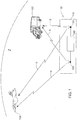
- Fig. 1 is a schematic illustration of a simplified architecture of a positioning system 10 according to an embodiment of the invention.
- the positioning system 10 includes a base station 110 of a known position, having at least two spaced-apart RF antennas (two antennas 120 and 130 are shown in Fig. 1 ) and a generating and switching unit 140 commonly coupled to the antennas.
- Base station 110 radiates a positioning signal S, which can be received at a certain local zone Z.
- a Platform 100 of an unknown position an airborne platform in this non-limiting example
- equipped with an RF receiver and one antenna not shown in Fig. 1
- flying in zone Z receives signal S and uses it for positioning.
- Also shown in Fig. 1 is another platform 102 (a ground vehicle) traveling within zone Z and receiving positioning signal from base station 110.
- Positioning Signal S is a periodic signal (e.g. a 1GHz sinusoidal signal) generated by unit 140 and switched between antenna 120 and antenna 130.
- signal S includes signal portions emitted by antenna 120 which alternates with signal portions emitted by antenna 130 (see discussion below referring to Fig. 6 ). Therefore, any platform within zone Z having an RF receiver equipped with a phase difference estimator for estimating the frequency and phase of the received signal (also known as a digital phase difference detector, see below with reference to Fig. 7 ) would be able to estimate the phase differences ⁇ between portions of the positioning signal emitted by antennas 120 and 130.
- a phase difference estimator for estimating the frequency and phase of the received signal
- Phase differences detected at one point within zone Z differ from those detected at another point (say, by platform 102 ), and correspond to the geometrical disposition of the receiver relative to antennas 120 and 130.
- antennas 120 and 130 are located apart from each other (e.g. by 10 meters)
- any platform within zone Z receiving signal S, detecting phase differences ⁇ and the frequency f of signal S is provided with information sufficient for the determination of its position relative to the known position of antennas 120 and 130.
- the position of the station is e.g. known to any platform traveling within zone Z, or is transmitted to the platform via a dedicated transmission or embedded in the positioning signal S.
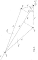
- FIG. 2 there is presented another illustration of the positioning system 10, showing the geometrical disposition of the positioning system operating in zone Z (zone Z is not shown in Fig. 2 ) and a platform 100 located within zone Z.
- Platform 100 is equipped with an RF receiver having a phase difference estimator allowing the estimation of the frequency f and phase differences ⁇ that characterize portions of signal S (this will be detailed further below with reference to Fig. 7 ).
- ⁇ R c 2 ⁇ N + ⁇ / 2 ⁇ f
- a surface CS is defined, which is the surface of a cone generated by angle ⁇ , onto which points 100, 120 and 130 are located.
- This provides information indicating the orientation of point 100 relative to points 120 and 130.
- the orientation of point 100 relative to points 120 and 130 could be determined using additional information, e.g. information gathered in a manner detailed below with reference to Fig. 3 , or elimination procedures known per-se in the field of interferometry (including but not limited to the use of the assumed or measured height of point 100).
- a system 110 further includes a third antenna 150, located at a distance R 4 away from antenna 120.
- signal S is generated by a common unit 140 and switched between the three spaced-apart antennas 120, 130 and 150.
- the positioning signal S includes signal portions that are alternatively transmitted by antennas 120, 130 and 150.
- Signal S, as received at point 100 therefore allows the estimation of the phase difference between portions of the positioning signal transmitted by antennas 120 and 130, as well as the phase difference between portions of the positioning signal transmitted by antennas 120 and 150, as detected at point 100.
- ⁇ 1 and ⁇ 2 are determined with respect to antenna 120 and antennas 130 and 100; and ⁇ 2 is determined with respect to antennas 120, 150 (the other antenna) and 100. Consequently, two Surfaces, CS 1 (representing the surface of a cone onto which points 100, 120 and 130 are located) and CS 2 (representing the surface of a cone onto which points 100, 120 and 150 are located) are defined. CS 1 and CS 2 intersect with each other, and the intersection line represents the pointing vector PV between antenna 120 and the unknown point 100. In other words, the orientation of the receiver relative to the positioning system could be determined.
- Fig. 4a schematically illustrates a positioning system 400 according to the embodiment of the invention illustrated in Fig. 3 .
- the system 400 comprises a base station 410 which is coupled to an array of three spaced-apart antennas, (namely antennas 120, 130 and 150 shown in Fig. 3 .
- Base station 410 comprises a signal generator 420 for generating a periodic signal (e.g. a sinusoidal signal). Also shown are an amplifier 430 and a switch 440 common to all antennas for switching the periodic signal between antennas 120, 130 and 150.
- a periodic signal e.g. a sinusoidal signal
- the antennas are coupled to base station 410 via substantially identical feed lines 411 (note that non-identical feed lines could also be used, with appropriate means for compensation for consequent delays), such that the output of base station 410 feeds the antennas in a switched manner, thereby giving rise to a positioning signal which includes portions of signal transmitted alternatively from the antennas.
- an RF receiver having a phase difference estimator and receiving the positioning signal e.g. platform 100 in Figs. 1-3 ) is able to determine the pointing vector to antenna 120.
- platform 100 is equipped with an altimeter (altitude meter)
- its position could be defined in a manner known per-se using the determination of the pointing vector PV between the platform and antenna 120, in combination with the readings of the altimeter at point 100 (unless point 100 is at the same height as the antennas).
- a positioning system 402 is shown in Fig. 4b .
- System 402 comprises an array of two antennas, 120 and 130.
- the base station 402 is further equipped with an accurate clock 450 (e.g. an atomic clock or a similar device).
- a platform receiving the positioning signal and having an atomic clock or a similar device in synchrony with clock 450 of the base station, is able to determine, in a manner known per-se, the distances between the platform (point 100 in Fig. 2 ) and antennas 120 and 130 (parameters R 1 , R 2 shown in Fig. 3 ), and its position.
- system 404 comprises an array of four antennas ( 120, 130, 150 and 170 ) .
- the base station 414 is substantially identical to base station 410 shown in Fig. 4a .
- the antenna array is arranged in a tetrahedron form, in which antennas 120, 130 and 150 are located onto the same plane, and antenna 170 is located outside that plane. Note that the three-dimensional arrangement of the antenna array affects the directivity and shape of Zone Z (the zone in which the positioning signal can be received). In case full symmetry is substantially maintained, the resultant positioning system is substantially omni-directional.
- FIG. 4e Another positioning system 406, according to yet another embodiment of the invention, is illustrated in Fig. 4e : in this embodiment, two positioning systems 408 and 409 operate in the same zone (this embodiment and additional embodiments, employing two adjacent positioning systems as will be detailed below, are hereinafter referred to as 'dual configuration' embodiments).
- Systems 408 and 409 can be any one of the types illustrated in Figs. 4a-4d .
- both systems are of the type illustrated in Figs. 4c- 4d, comprising an array of four antennas ( 122, 132, 152, 172 and 124, 134, 154 and 174, respectively) and base stations 416 and 418, respectively.
- the position of the RF receiver could be determined based on positioning information obtained from a pair of positioning systems of the type described with reference to Fig. 2 , also illustrated in Fig. 4f .
- This type of dual configuration system comprises two positioning systems, each having a base station (e.g. base station 410 shown in Fig. 4a ) and an array of two antennas (e.g. antennas 120 and 130 illustrated in Fig. 2 ).
- a positioning signal switched and emitted by an array of two antennas 120 and 130 and received at point 100 allows the determination of a surface plane of a cone, onto which are located points 100, 120 and 130 . Therefore, in this dual configuration, two cones are thus determined.
- both positioning systems need not be identical in their structure. Therefore, one positioning system could be of the type shown in Fig. 4c , and the other of the types shown in Figs. 4a-4b or discussed above, all as required.
- Figs. 4e and 4f relating to the 'dual configuration , the base stations (e.g. elements 416 and 418 shown in Fig. 4e ) were presented as a separate unit. It should be understood that the 'dual configuration' of the invention can be implemented with a single base station coupled to and operating dual arrays of antennas, such that each antenna array constitutes its own positioning signal.
- the ambiguity of N is solved in the following manner, discussed with reference to Fig. 5 together with Fig. 2 : in order to determine N, the positioning signal S includes signal portions having a first frequency f 1 , and signal portions having a second frequency, f 2 . The signal portions having the frequency f 1 are switched between and emitted by all the antennas at the antenna array (two antennas 120 and 130 in the example shown in Fig.
- a receiver having a phase difference estimator located at point 100 will measure a first phase difference ⁇ 1 corresponding to the first frequency f 1 , and a second phase difference ⁇ 2 , corresponding to the second frequency f 2 .
- N 1 (k) f 1 ⁇ 1 + f 2 ⁇ 2 / 2 ⁇ f 2 ⁇ f 1 + f 1 k / f 2 ⁇ f 1
- N 1 is determined as the optimal solution of relation (7) (e.g. when the minimum of a truncN 1 or (1 - truncN 1 ) is achieved).
- the periodic signal includes two frequencies of a predefined difference (e.g.
- the predefined difference gives rise to a limited set of values for k, and therefore the value of N could be easily determined by measuring parameters f and ⁇ of signal portions of both frequencies (that is, parameters f 1 , f 2 , ⁇ 1 and ⁇ 2 ).
- Fig. 5 is a flow chart showing a sequence of operations 500 carried out by the receiver (platform 100 shown in Fig. 1 ) for the determination of parameter N:
- the positioning signal S includes signal portions having a first frequency f 1 , and signal portions having a second frequency, f 2 .
- the signal portions having the frequency f 1 are switched between and emitted by all the antennas at the antenna array, as well as those having the frequency f 2 .
- a schematic illustration of a positioning signal S as generated for example, by the positioning system 402 shown in Fig. 4b is illustrated in Fig. 6 . It should be noted that the portions transmitted by one antenna need not be identical in length to those transmitted by the other antenna/s.
- the timing and duration of the switching of the signal between the transmitting antennas can be changed along the transmission of the positioning signal. Furthermore, there is no need to sequence f 2 portions after each f 1 portions of signal, and other combinations are possible. Furthermore, additional signal portions carrying additional information (e.g. the identity of the base station, and more) could be embedded in the positioning signal.
- the positioning signal needs to be transmitted in a continuous manner while being alternately switched between the antennas.
- phase difference between portions of positioning signal alternatively transmitted by the different antennas is affected by the geometrical arrangement of the antennas. Furthermore, the phase difference is detected by the receiver by comparing a portion of the positioning signal with a delayed portion of the same positioning signal.
- Fig. 7 is a schematic illustration of a receiver 700 designed for receiving a positioning signal generated and transmitted by a positioning system according to the invention as described above, and for determining its position accordingly.
- Receiver 700 can be mounted onboard a flying object, e.g. an aircraft, an Airborne Unmanned Vehicle (AUV), a missile, etc., or any other type of moving or stationary object.
- Receiver 700 is operable with one antenna only.
- Receiver 700 comprises, inter-alia, a single antenna 710, a phase difference estimator 720 and a positioning hardware/software utility 730.
- the phase difference estimator 720 can be realized based on any devices and methods known in the art for estimating phase differences.
- phase difference estimator 720 may include a digital comparator for comparing a currently received portion of signal with a previously received portion of the same signal (a portion fed via a delay component, e.g. a FIFO (First In First Out) buffer providing a 0.5 ⁇ sec. delay).
- the phase difference estimator 720 can be realized based on a Modulation-on-Pulse device, known in the art.
- Positioning utility 730 comprises an f/ ⁇ determination module 740 for determining the frequency f and phase ⁇ of various portions of the received signal, N determination module 750 for determination of parameter N (see discussion above with reference to Fig. 5 ), and position determination module 760 for calculating the position of the receiver.
- Fig. 7 are Analog-to Digital converters, which may be required.
- Receiver 700 is illustrated in Fig. 7 in a non-limiting manner as a stand-alone receiver.
- the receiver can be integrated with onboard hardware without departing from the scope of the invention.
- the receiver could comprise only a positioning utility (element 730 ), and be coupled to on-board antenna and phase difference estimator, also used for other purposes.
- the positioning utility 730 could be implemented as a software utility operable by an onboard computer for positioning purposes.
- the receiver could serve as a transponder and comprise only a transmit/receive module, and transpond the positioning signal to a remote control station, which analyzes the signal, determines the position of the receiver and, if required, transmits it navigation and/or guidance information.
- Fig. 8 illustrates a positioning method according to an embodiment of the invention, showing a sequence of operations 800 carried out for determining position information indicative of the position of a receiver of unknown position, receiving a positioning signal generated and transmitted by a positioning system according to the invention.
- the positioning method comprises the following operations:
- the position of the receiver relative to the antennas could be determined, as described above.
- the invention was described mainly with reference to an airborne platform. It should be noted that the invention is also applicable for ground and sea-borne vehicles, with the required alterations and modifications. The invention could also be realized as a hand-held mobile device.
- the concept of the present invention can be implemented in a system that involves two-way communication of the base station with the platform of the unknown location, e.g. a guided UAV (Unmanned Airborne Vehicle), a mobile wireless communication device, etc.
- the returned signal coming from the platform allows, in a manner known per-se, to determine the range between the platform and the base station.
- the direction of the platform relative to the base station can be determined, and in combination the positioning of the platform is established.
- the platform communicates with the base station, it is possible to have the platform operate as a transponder, returning to the base station the signal coming therefrom as received by the transponder. In such a case, it is also possible to conduct all position calculations at the base station (or at another station connected thereto), and e.g. provide the platform with flight instructions based on its calculated position.
- the present invention could be integrated with a cellular communication network, e.g. for supporting geographically-based services.
- a cellular communication network is formed as a grid of cells covering a service area.
- network components e.g. cell site or base station, including transmitting/receiving equipment
- Each mobile communication device communicates in a timely manner with its cell site, receiving and returning a control signal, thereby providing the network with information indicating the current range between the mobile device and the serving cell site.
- the specific position of the mobile device within a cell is unknown to the network. For example, as is clear in light of the detailed discussion above, by proving a cell site having two antennas and switching the control signal therebetween information about the direction of the mobile device relative to the cell site can be established.
- the present invention could be integrated with other positioning systems (e.g. GPS system), in order to validate the readings of such other positioning systems.
- the present invention could be used that way to indicate jamming or deception of the GPS signal, or to calibrate INS (Inertial Navigation System) drifts.
- INS Inertial Navigation System
- the present invention could also be used for correlating timed information between different and remote systems.
- the positioning system provides high precision position measurements.
- the precision is affected by the range of frequencies, and it is clear that at higher frequencies, better precision is yielded. However, in order to provide greater system range, lower frequencies are required. Note that while at the frequency range of about 1GHz, Line Of Sight (LOS) transmission is required; this limitation is decreased at lower frequencies.
- the precision is further affected by the geometry of the array of the antennas which are coupled to a common switch, and in the dual configuration' of the invention, also by the geometry of the two antenna arrays. Additional precision is achieved by averaging phase measurements over a period of time (e.g. over 1 msec.). System errors are minimal as there is no need to compensate for receiver errors and to correlate readings from different receivers.
- the positioning system provides high update rate.
- the update rate is affected by the width of the periodic signal as well as by the length of the switching cycle (i.e. the length of time needed for transmission of the periodic signal by all antennas in the antenna array). For example, by setting the width of a 1GHz periodic signal to 1 msec, and the length of the switching cycle to 4 msec, a 100KHz update rate is maintained. Note that high update rate provides better navigation precision and better signal-to-noise ratio, and consequently, larger coverage area.
- the positioning system is better protected against blocking and jamming.
- the positioning signal available to receivers located within the coverage area of the positioning system is stronger than the GPS signal available in most areas covered by the GPS system, and therefore a stronger signal is required for blocking and jamming.
- the invention was described with reference to RF radiation, and mamly to RF radiation of frequencies of about 1Ghz. It should be noted that the.invention is not limited by the exemplified frequencies, and could be employed along other portions of the radio spectrum as well as other electromagnetic radiation spectra. Furthermore, the invention is not limited to electromagnetic radiation and is applicable to any other form of propagating wave-borne energy, such as acoustic, ultrasonic, etc.
- positioning systems were described as stand-alone systems. It should be noted that a positioning system according to the invention could be integrated with other systems e.g. other positioning systems, direction-finders, radar systems and many more, with the required alterations and modifications.
Landscapes
- Engineering & Computer Science (AREA)
- Computer Networks & Wireless Communication (AREA)
- Physics & Mathematics (AREA)
- General Physics & Mathematics (AREA)
- Radar, Positioning & Navigation (AREA)
- Remote Sensing (AREA)
- Position Fixing By Use Of Radio Waves (AREA)
Claims (15)
- Système de positionnement utilisable pour permettre la détermination de la position d'un récepteur RF distant, le système comprenant :un réseau d'antennes constitué d'au moins deux antennes espacées (120, 130, 150, 170), la distance entre les antennes espacées étant connue, ledit réseau d'antennes étant couplé à une unité commune de génération et de commutation (140), ladite unité de génération et de commutation étant configurée pour générer un signal périodique S et pour commuter le signal périodique S entre lesdites deux antennes ou plus dudit réseau d'antennes, où Δt représente le retard entre des parties du signal périodique S émis par les antennes espacées,dans lequel un récepteur RF distant peut recevoir ledit signal périodique S et un dispositif d'estimation de différence de phases (720) peut mesurer la différence de phases ϕ entre des parties dudit signal périodique S présentant la même fréquence, ladite différence de phases indiquant au moins une surface, la surface incluant au moins un cône et le récepteur RF distant étant situé sur le ou les cônes, etdans lequel l'angle α du ou des cônes est défini sur la base de la fréquence respective dudit signal périodique S détecté par le récepteur RF distant, la différence de phases ϕ et un nombre entier N de cycles dudit signal périodique S correspondant à la différence ΔR de distance de trajet depuis les antennes, le retard Δt entre les parties du signal périodique S et la distance connue entre les antennes,le système étant caractérisé en ce que :ladite unité de génération et de commutation est configurée pour générer ledit signal périodique S incluant des parties de signal présentant une première fréquence f1 et des parties de signal présentant une seconde fréquence f2, ainsi que pour commuter le signal entre les deux antennes plus de sorte à ce que les parties de signal de la première fréquence soient commutées entre les deux antennes espacées ou plus et soient suivies par les parties de signal de la seconde fréquence qui sont commutées entre les deux antennes espacées ou plus,dans lequel ledit dispositif d'estimation de différence de phases peut mesurer ladite différence de phases comme première différence de phase entre des parties de signal de ladite première fréquence f1 et comme seconde différence de phases entre des parties de signal de ladite seconde fréquence f2,dans lequel le nombre N est déterminé en utilisant les première et seconde différences de phases.
- Système selon la revendication 1, dans lequel lesdites antennes espacées sont couplées à l'unité commune de génération et de commutation par l'intermédiaire de lignes d'alimentation pratiquement identiques.
- Système selon l'une quelconque des revendications 1 et 2, dans lequel ledit réseau d'antennes inclut au moins trois antennes ce qui autorise ainsi la détermination d'un vecteur de pointage entre ledit récepteur RF distant et ledit réseau d'antennes.
- Système selon l'une quelconque des revendications précédentes, dans lequel ledit réseau d'antennes comprend quatre antennes sous la forme d'un tétraèdre.
- Système comprenant le système de positionnement conforme à l'une quelconque des revendications 1 à 4, comprenant en outre ledit récepteur RF distant et le dispositif d'estimation de différence de phases qui lui est accouplé.
- Système selon la revendication 5, comprenant en outre une plate-forme (100) munie du récepteur RF distant, la plate-forme étant munie d'un altimètre, ou
dans lequel ladite unité de commutation et de génération est couplée à une première horloge précise, et ledit récepteur RF distant est associé à une seconde horloge précise, ladite seconde horloge étant synchronisée avec ladite première horloge et ledit système étant configuré pour déterminer la position dudit récepteur. - Système selon l'une quelconque des revendications 1 à 4, dans lequel ledit récepteur RF distant est un répondeur, ledit répondeur étant configuré pour recevoir ledit signal périodique S et renvoyer ledit signal périodique S à une station de télécommande, ladite station de télécommande étant configurée pour analyser le signal et pour déterminer la position dudit récepteur RF distant.
- Système selon l'une quelconque des revendications 1 à 5, comprenant en outre un second réseau d'antennes comprenant au moins deux antennes espacées, configuré pour transmettre un second signal périodique de positionnement, ledit signal périodique S étant un premier signal périodique de positionnement et ladite surface étant la première surface d'un cône,
le récepteur RF est configuré pour recevoir le premier et le second signal périodique de positionnement, et
dans lequel ledit dispositif d'estimation de différence de phases est en outre capable de mesurer d'autres différences de phases entre des parties du second signal de positionnement, lesdites parties étant séparées par un retard, lesdites parties différentes du second signal de positionnement étant transmises par une antenne différente du second réseau d'antennes et lesdites autres différences de phases indiquant au moins une seconde surface de cône entre ledit second réseau d'antennes et ledit récepteur, et où l'intersection entre ladite première surface de cône et ladite seconde surface de cône détermine une ligne sur laquelle est situé le récepteur. - Système selon la revendication 8, dans lequel chacun des premier et second signaux de positionnement inclut les parties de signal d'au moins une première fréquence et une seconde fréquence, ladite ou lesdites unités de génération et de commutation étant en outre configurées pour commuter le signal entre les deux antennes ou plus dans le second réseau d'antennes de sorte à ce que les parties de signal de la première fréquence soient commutées entre les deux antennes espacées ou plus et soient suivies par des parties de signal de seconde fréquence qui sont commutées entre les deux antennes espacées ou plus.
- Système selon la revendication 8 ou la revendication 9, dans lequel le second réseau d'antennes comprend au moins trois antennes ce qui autorise la détermination de la position dudit récepteur.
- Système selon la revendication 1, intégré dans un réseau de communication cellulaire, ledit réseau de communication cellulaire comprenant au moins un site de cellule et au moins un dispositif cellulaire, ledit réseau d'antennes d'au moins deux antennes espacées étant intégré avec ledit ou lesdits sites de cellules et un dispositif cellulaire étant muni du récepteur RF distant, et ledit système étant configuré pour autoriser le positionnement dudit dispositif cellulaire dans ledit système de communication.
- Système selon la revendication 9, dans lequel, pour chacun desdits premier et dudit second signal de positionnement, ledit dispositif d'estimation de différence de phases est configuré pour mesurer une première différence de phases entre des parties de signal de ladite première fréquence et une seconde différence de phases entre des parties de signal de ladite seconde fréquence.
- Procédé permettant d'activer la détermination de la position d'un récepteur comportant un dispositif d'estimation de différence de phases, le récepteur pouvant être monté sur une plate-forme (100), le procédé comprenant :- la réception, par le récepteur, d'un signal périodique S transmis et commuté entre au moins deux antennes espacées d'emplacements connus, couplées à une unité commune de génération et de commutation, la distance entre les antennes espacées étant connue,- la mesure (820), par le dispositif d'estimation de différence de phases, d'une différence de phases ϕentre des parties dudit signal périodique S reçu par ledit récepteur, lesdites parties étant séparées par un retard Δt et présentant la même fréquence f, chaque partie étant transmise par l'une desdites deux antennes espacées ou plus, et- sur la base de ladite différence de phases ϕ, la récupération d'informations au moins indicatives d'une surface, la surface incluant au moins un cône et le récepteur étant situé sur le ou les cônes,dans lequel l'angle α du ou des cônes est défini sur la base de la fréquence respective dudit signal périodique S détecté par le récepteur RF, la différence de phases ϕ et un nombre entier N de cycles dudit signal périodique S correspondant à la différence ΔR de distance de trajet depuis les antennes, le retard Δt entre les parties du signal périodique S et la distance connue entre les antennes,
dans lequel ledit signal périodique S inclut des parties de signal d'au moins une première fréquence f1 et des parties de signal d'au moins une seconde fréquence f2, et dans lequel les parties du signal présentant ladite ou lesdites premières fréquences f1 sont commutées entre lesdites deux antennes espacées ou plus et sont suivies par des parties de signal de la seconde fréquence f2 qui sont commutées entre lesdites deux antennes espacées ou plus,
le procédé comprenant en outre la mesure, par le dispositif d'estimation de différence de phases, de ladite différence de phases comme étant une première différence de phases entre des parties de signal de ladite première fréquence f1 et une seconde différence de phases entre des parties de signal de ladite seconde fréquence f2,
dans lequel le nombre N est déterminé en utilisant les première et seconde différences de phases. - Procédé selon la revendication 13, comprenant en outre :
la génération du signal périodique S et la commutation du signal entre lesdites deux antennes ou plus dudit réseau d'antennes afin de générer ainsi des parties séparées par le retard Δt et présentant la même fréquence, ainsi que la transmission des différentes parties par une antenne différente desdites deux antennes ou plus. - Procédé selon la revendication 13 ou la revendication 14, dans lequel le signal périodique S est un premier signal périodique et ladite surface est une première surface de cône, le procédé comprenant en outre :- la réception d'un second signal périodique, ledit second signal périodique étant commuté entre au moins deux antennes espacées d'un second réseau d'antennes et dans lequel lesdites antennes espacées desdits premier et second réseaux d'antennes proviennent d'emplacements connus et sont couplées à une autre unité commune de génération et de commutation,- la mesure, par le dispositif d'estimation de différence de phases, des différences de phases entre des parties du signal respectif reçu par ledit récepteur, lesdites parties étant séparées par un retard et présentant la même fréquence, et chaque partie étant transmise par une antenne différente desdites deux antennes espacées ou plus,- la détermination d'informations indicatives d'une seconde surface de cône entre ledit second réseau d'antennes et ledit récepteur, et- la détermination d'une intersection entre ladite première surface de cône et ladite seconde surface de cône, ladite intersection déterminant une ligne sur laquelle est situé ledit récepteur.
Applications Claiming Priority (2)
| Application Number | Priority Date | Filing Date | Title |
|---|---|---|---|
| IL169855A IL169855A (en) | 2005-07-25 | 2005-07-25 | A system and method for locating a receiver location |
| PCT/IL2006/000863 WO2007013071A1 (fr) | 2005-07-25 | 2006-07-25 | Système de positionnement et procédé |
Publications (2)
| Publication Number | Publication Date |
|---|---|
| EP1910860A1 EP1910860A1 (fr) | 2008-04-16 |
| EP1910860B1 true EP1910860B1 (fr) | 2021-06-16 |
Family
ID=37027717
Family Applications (1)
| Application Number | Title | Priority Date | Filing Date |
|---|---|---|---|
| EP06766178.5A Active EP1910860B1 (fr) | 2005-07-25 | 2006-07-25 | Système de positionnement et procédé |
Country Status (5)
| Country | Link |
|---|---|
| US (1) | US8249618B2 (fr) |
| EP (1) | EP1910860B1 (fr) |
| IL (1) | IL169855A (fr) |
| SG (1) | SG159527A1 (fr) |
| WO (1) | WO2007013071A1 (fr) |
Families Citing this family (17)
| Publication number | Priority date | Publication date | Assignee | Title |
|---|---|---|---|---|
| IL169854A (en) * | 2005-07-25 | 2013-11-28 | Elta Systems Ltd | System and method for finding receiver-transmitter location |
| JP4900360B2 (ja) * | 2008-10-17 | 2012-03-21 | ソニー株式会社 | 受信装置、移動角度推定方法、プログラム、および無線通信システム |
| US20120313820A1 (en) * | 2011-06-07 | 2012-12-13 | Raytheon Company | System technique for conical geo-location of radio frequency sources |
| US8907846B2 (en) * | 2013-02-05 | 2014-12-09 | King Fahd University Of Petroleum And Minerals | Single-antenna direction finding system for multi-rotor platforms |
| US9606224B2 (en) * | 2014-01-14 | 2017-03-28 | Alstom Transport Technologies | Systems and methods for vehicle position detection |
| CN104090265B (zh) * | 2014-07-04 | 2016-10-05 | 北京智谷睿拓技术服务有限公司 | 定位方法和设备 |
| US11086019B2 (en) * | 2015-06-12 | 2021-08-10 | Robotic Researchh, LLC | Atomic clock base navigation system for on-the-move radar, obfuscation, sensing, and ad-hoc third party localization |
| DE102015122420A1 (de) | 2015-12-21 | 2017-06-22 | Fraunhofer-Gesellschaft zur Förderung der angewandten Forschung e.V. | Sendeanordnung zum Erzeugen eines für eine Lokalisierung geeigneten Signalmusters und Empfangsanordnung zum Durchführen einer Lokalisierung |
| US11874386B2 (en) | 2017-02-01 | 2024-01-16 | Cobham Advanced Electronic Solutions, Inc. | RF polarimeters with optical delay lines |
| US10725142B2 (en) * | 2017-02-01 | 2020-07-28 | Cobham Advanced Electronic Solutions, Inc. | Single channel interferometer with optical delay lines |
| JP7144801B2 (ja) * | 2018-06-01 | 2022-09-30 | 国立大学法人京都大学 | 計測装置、受電装置、送電装置、および飛行システム |
| CN109001768B (zh) * | 2018-07-31 | 2022-09-13 | 太原理工大学 | 一种应用于天线中的改进双极化顺序ml多径抑制方法 |
| CN112787417A (zh) * | 2019-11-04 | 2021-05-11 | 北京小米移动软件有限公司 | 无线能量发射装置、无线能量接收装置、无线供能方法及系统 |
| CN112769251B (zh) * | 2019-11-04 | 2022-11-22 | 北京小米移动软件有限公司 | 无线能量发射装置及电子设备 |
| JP2021197638A (ja) * | 2020-06-15 | 2021-12-27 | 株式会社東海理化電機製作所 | 通信制御装置及び通信制御方法 |
| WO2022096511A1 (fr) * | 2020-11-04 | 2022-05-12 | Lambda:4 Entwicklungen Gmbh | Procédé de télémétrie par radio unilatérale |
| CN112782728B (zh) * | 2021-01-26 | 2024-03-22 | 中国人民解放军92728部队 | 一种基于惯性辅助的天线阵欺骗干扰信号检测方法 |
Citations (1)
| Publication number | Priority date | Publication date | Assignee | Title |
|---|---|---|---|---|
| US20010020917A1 (en) * | 2000-02-23 | 2001-09-13 | Fujitsu Limited | Radio transceiver and method of controlling direction of radio-wave emission |
Family Cites Families (60)
| Publication number | Priority date | Publication date | Assignee | Title |
|---|---|---|---|---|
| US1532178A (en) * | 1921-07-25 | 1925-04-07 | Louis A Godbold | Lubricator |
| US3808597A (en) | 1968-03-14 | 1974-04-30 | Teledyne Inc | Iso-phase position determining system |
| US3647809A (en) * | 1968-04-26 | 1972-03-07 | Chinoin Gyogyszer Es Vegyeszet | Certain pyridyl-1 2 4-oxadiazole derivatives |
| GB1468016A (en) | 1973-11-16 | 1977-03-23 | Decca Ltd | Phase comparison radio navigation systems |
| US3946385A (en) * | 1975-01-20 | 1976-03-23 | The United States Of America As Represented By The Secretary Of The Department Of Transportation | Interferometric navigation and guidance system |
| US4022901A (en) * | 1975-03-05 | 1977-05-10 | E. R. Squibb & Sons, Inc. | 3-Pyridinyl-5-isothiocyanophenyl oxadiazoles |
| CA1050140A (fr) * | 1975-12-19 | 1979-03-06 | National Research Council Of Canada | Indicateur de position radio vlf |
| DE2715383C3 (de) | 1977-04-06 | 1981-02-19 | Standard Elektrik Lorenz Ag, 7000 Stuttgart | Funknavigationsanlage |
| US4283726A (en) * | 1978-09-05 | 1981-08-11 | Lewis C. Spence | Dual frequency distance measuring system |
| DE2843253A1 (de) | 1978-10-04 | 1980-04-17 | Standard Elektrik Lorenz Ag | Navigationssystem zur richtungs- und entfernungsmessung |
| FR2481465A1 (fr) | 1980-04-25 | 1981-10-30 | Trt Telecom Radio Electr | Procede et dispositif pour la determination precise d'azimut a partir de la mesure de plusieurs dephasages |
| US4386668A (en) * | 1980-09-19 | 1983-06-07 | Hughes Tool Company | Sealed lubricated and air cooled rock bit bearing |
| SE442348B (sv) | 1984-07-04 | 1985-12-16 | Stiftelsen Inst Mikrovags | Forfarande och anordning for bestemning av inbordes lege mellan tva objekt |
| US5236952A (en) * | 1986-03-11 | 1993-08-17 | Hoffmann-La Roche Inc. | Catechol derivatives |
| YU213587A (en) * | 1986-11-28 | 1989-06-30 | Orion Yhtymae Oy | Process for obtaining new pharmacologic active cateholic derivatives |
| US5099245A (en) * | 1987-10-23 | 1992-03-24 | Hughes Aircraft Company | Vehicle location system accuracy enhancement for airborne vehicles |
| US4975710A (en) | 1989-08-01 | 1990-12-04 | Baghdady Elie J | Methods and apparatus for direction of arrival measurement and radio navigation aids |
| US5084709A (en) | 1990-05-17 | 1992-01-28 | Baghdady Elie J | Method and apparatus for radio location |
| US5126513A (en) * | 1991-05-10 | 1992-06-30 | U.S. Philips Corporation | Interactive display system |
| US5883598A (en) | 1995-12-15 | 1999-03-16 | Signatron Technology Corporation | Position location system and method |
| US6206110B1 (en) * | 1996-09-09 | 2001-03-27 | Smith International, Inc. | Protected lubricant reservoir with pressure control for sealed bearing earth boring drill bit |
| US6270433B1 (en) | 1997-12-15 | 2001-08-07 | Toy Builders | Player position detection system |
| JP2002526482A (ja) * | 1998-09-18 | 2002-08-20 | バーテックス ファーマシューティカルズ インコーポレイテッド | p38のインヒビター |
| US6660753B2 (en) * | 1999-08-19 | 2003-12-09 | Nps Pharmaceuticals, Inc. | Heteropolycyclic compounds and their use as metabotropic glutamate receptor antagonists |
| US6347229B1 (en) | 1999-08-26 | 2002-02-12 | Intech 21, Inc. | Method for tracking the location of mobile units |
| US6489923B1 (en) | 1999-09-16 | 2002-12-03 | Nortel Networks Limited | Position location method and apparatus for a mobile telecommunications system |
| US6590498B2 (en) | 1999-10-19 | 2003-07-08 | Lucent Technologies Inc. | Method and apparatus for improving the interrogation range of an RF-Tag |
| CN1280640C (zh) | 2000-06-05 | 2006-10-18 | Tc许可有限公司 | 确定调制的反向散射通信系统中应答器方向的方法和设备 |
| US6868073B1 (en) | 2000-06-06 | 2005-03-15 | Battelle Memorial Institute K1-53 | Distance/ranging by determination of RF phase delta |
| US7024331B2 (en) | 2000-11-15 | 2006-04-04 | Scientific Generics Limited | Tag tracking |
| US20040097555A1 (en) * | 2000-12-26 | 2004-05-20 | Shinegori Ohkawa | Concomitant drugs |
| US6784826B2 (en) * | 2001-01-26 | 2004-08-31 | Tera Research Incorporated | Body motion tracking system |
| US6876326B2 (en) | 2001-04-23 | 2005-04-05 | Itt Manufacturing Enterprises, Inc. | Method and apparatus for high-accuracy position location using search mode ranging techniques |
| JP2005504014A (ja) * | 2001-06-08 | 2005-02-10 | サイトビア インコーポレイテッド | カスパーゼの活性化因子およびアポトーシスの誘導因子としての置換された3−アリール−5−アリール−[1,2,4]−オキサジアゾール類および類似体、並びにその使用法 |
| US6700536B1 (en) * | 2001-10-25 | 2004-03-02 | Richard J. Wiegand | System and method for determining a direction of incident electromagnetic signals |
| FI111037B (fi) * | 2002-02-25 | 2003-05-15 | Nokia Corp | Menetelmä ja järjestelmä elektroniikkalaitteen sijainnin määrittämiseksi ja elektroniikkalaite |
| JP2003339070A (ja) * | 2002-05-21 | 2003-11-28 | Hitachi Ltd | 位置検出システムおよび携帯端末およびサーバ |
| WO2004002012A1 (fr) | 2002-06-21 | 2003-12-31 | Siemens Aktiengesellschaft | Determination de la position d'un utilisateur dans un systeme de communication radio a diversite d'emission |
| CN100364531C (zh) * | 2002-12-18 | 2008-01-30 | 西托维亚公司 | 3,5-二取代-[1,2,4]-二唑及类似物和其用途 |
| WO2005006945A2 (fr) * | 2003-07-03 | 2005-01-27 | The Salk Institute For Biological Studies | Procedes de traitement de troubles neurologiques et composes utiles a cet effet |
| US6914559B2 (en) * | 2003-09-22 | 2005-07-05 | Northrop Grumman Corporation | Direction finding method and system using digital directional correlators |
| GB0325956D0 (en) * | 2003-11-06 | 2003-12-10 | Addex Pharmaceuticals Sa | Novel compounds |
| US7260408B2 (en) | 2004-02-20 | 2007-08-21 | Airespace, Inc. | Wireless node location mechanism using antenna pattern diversity to enhance accuracy of location estimates |
| WO2005105780A2 (fr) * | 2004-04-28 | 2005-11-10 | Vertex Pharmaceuticals Incorporated | Compositions utiles en tant qu'inhibiteurs de la rock et d'autres proteines kinases |
| US20080051441A1 (en) * | 2004-12-28 | 2008-02-28 | Astrazeneca Ab | Aryl Sulphonamide Modulators |
| US7778651B2 (en) | 2005-02-16 | 2010-08-17 | Harris Corporation | Wireless network range estimation and associated methods |
| US8017631B2 (en) * | 2005-04-26 | 2011-09-13 | Neurosearch A/S | Oxadiazole derivatives and their medical use |
| GB0510139D0 (en) * | 2005-05-18 | 2005-06-22 | Addex Pharmaceuticals Sa | Novel compounds B1 |
| US7553964B2 (en) * | 2005-06-03 | 2009-06-30 | Abbott Laboratories | Cyclobutyl amine derivatives |
| IL169854A (en) * | 2005-07-25 | 2013-11-28 | Elta Systems Ltd | System and method for finding receiver-transmitter location |
| PL1907382T3 (pl) * | 2005-07-26 | 2016-01-29 | Bial Portela & Ca Sa | Pochodne nitrokatecholowe jako inhibitory COMT |
| FR2889525A1 (fr) * | 2005-08-04 | 2007-02-09 | Palumed Sa | Nouveaux derives de polyquinoleines et leur utilisation therapeutique. |
| US20070048384A1 (en) * | 2005-08-26 | 2007-03-01 | Joerg Rosenberg | Pharmaceutical compositions |
| EP1954137A4 (fr) * | 2005-11-18 | 2008-12-17 | Janssen Pharmaceutica Nv | 2-ceto-oxazoles en tant que modulateurs d'amide d'acide gras hydrolase |
| WO2007063946A1 (fr) * | 2005-11-30 | 2007-06-07 | Fujifilm Ri Pharma Co., Ltd. | Diagnostic et remede pour une maladie provoquee par l’aggregation et/ou le depot d’amyloide |
| EP1845097A1 (fr) * | 2006-04-10 | 2007-10-17 | Portela & Ca., S.A. | Derives de oxadiazole en tant qu' inhibiteurs de l'enzyme COMT |
| US20080167286A1 (en) * | 2006-12-12 | 2008-07-10 | Abbott Laboratories | Pharmaceutical compositions and their methods of use |
| US8486979B2 (en) * | 2006-12-12 | 2013-07-16 | Abbvie Inc. | 1,2,4 oxadiazole compounds and methods of use thereof |
| BRPI0721213B1 (pt) * | 2007-01-31 | 2021-11-09 | Bial - Portela & Ca, S.A. | Uso de nitrocatecóis substituídos, e embalagem |
| MX2010009043A (es) * | 2008-02-28 | 2010-10-25 | Bial Portela & Ca Sa | Composicion farmaceutica para farmacos poco solubles. |
-
2005
- 2005-07-25 IL IL169855A patent/IL169855A/en active IP Right Grant
-
2006
- 2006-07-25 US US11/989,477 patent/US8249618B2/en active Active
- 2006-07-25 EP EP06766178.5A patent/EP1910860B1/fr active Active
- 2006-07-25 WO PCT/IL2006/000863 patent/WO2007013071A1/fr not_active Ceased
- 2006-07-25 SG SG201000797-9A patent/SG159527A1/en unknown
Patent Citations (1)
| Publication number | Priority date | Publication date | Assignee | Title |
|---|---|---|---|---|
| US20010020917A1 (en) * | 2000-02-23 | 2001-09-13 | Fujitsu Limited | Radio transceiver and method of controlling direction of radio-wave emission |
Also Published As
| Publication number | Publication date |
|---|---|
| IL169855A (en) | 2014-05-28 |
| WO2007013071A1 (fr) | 2007-02-01 |
| US8249618B2 (en) | 2012-08-21 |
| US20090111483A1 (en) | 2009-04-30 |
| SG159527A1 (en) | 2010-03-30 |
| EP1910860A1 (fr) | 2008-04-16 |
Similar Documents
| Publication | Publication Date | Title |
|---|---|---|
| US8229472B2 (en) | System and method for enabling determination of a position of a transponder | |
| EP1910860B1 (fr) | Système de positionnement et procédé | |
| US10620296B1 (en) | System for positioning, navigation, and time (PNT) | |
| US8120526B2 (en) | Methods, apparatuses and systems for locating non-cooperative objects | |
| Han et al. | Future alternative positioning, navigation, and timing techniques: A survey | |
| Chen et al. | Determining RF angle of arrival using COTS antenna arrays: A field evaluation | |
| EP2523019B1 (fr) | Réception de signaux de système mondial de positionnement présentant une résistance accrue aux interférences | |
| EP2449626A1 (fr) | Antenne réseau à commande de phase conformée à auto-étalonnage | |
| US10754002B1 (en) | Method and apparatus for determining the direction of arrival of radio or acoustic signals, and for transmitting directional radio or acoustic signals | |
| EP2870489B1 (fr) | Procédé de détermination de direction vers un objet émettant un signal | |
| del Peral-Rosado et al. | Design considerations of dedicated and aerial 5G networks for enhanced positioning services | |
| CN101156077A (zh) | 具有稀疏天线阵列的定位系统 | |
| KR102287852B1 (ko) | 무인항공기용 전파측위시스템 및 무인항공기용 항행방법 | |
| US11300687B2 (en) | Discriminating and mitigating SNS spoofing signals | |
| RU2739486C1 (ru) | Способ пеленгования источника радиосигнала | |
| Friedman et al. | Angle-of-arrival assisted radio interferometry (ARI) target localization | |
| US8952848B2 (en) | System and method for determining the location of the phase center of an antenna | |
| Gumiero et al. | Multistatic passive radar geometry optimization for target 3D positioning accuracy | |
| Fabrizio | Geolocation of HF skywave radar signals using multipath in an unknown ionosphere | |
| EP3583441A1 (fr) | Géolocalisation multi-récepteur à l'aide de gps différentiel | |
| US10390581B1 (en) | Radio frequency head tracker | |
| Weinzierl et al. | Blind Geolocation of RF-Signals with LEO Satellite Formations | |
| Cheung et al. | Differencing Methods for 3D Positioning of Spacecraft | |
| Li et al. | An effective integrated communication and localization method based on digital phased array antenna | |
| EP4502642A1 (fr) | Système de navigation cellulaire basé sur le doppler |
Legal Events
| Date | Code | Title | Description |
|---|---|---|---|
| PUAI | Public reference made under article 153(3) epc to a published international application that has entered the european phase |
Free format text: ORIGINAL CODE: 0009012 |
|
| 17P | Request for examination filed |
Effective date: 20080218 |
|
| AK | Designated contracting states |
Kind code of ref document: A1 Designated state(s): AT BE BG CH CY CZ DE DK EE ES FI FR GB GR HU IE IS IT LI LT LU LV MC NL PL PT RO SE SI SK TR |
|
| RIN1 | Information on inventor provided before grant (corrected) |
Inventor name: FRIEAIZEN, MOSHE |
|
| 17Q | First examination report despatched |
Effective date: 20110505 |
|
| RIN1 | Information on inventor provided before grant (corrected) |
Inventor name: FIREAIZEN, MOSHE |
|
| DAX | Request for extension of the european patent (deleted) | ||
| STAA | Information on the status of an ep patent application or granted ep patent |
Free format text: STATUS: EXAMINATION IS IN PROGRESS |
|
| GRAP | Despatch of communication of intention to grant a patent |
Free format text: ORIGINAL CODE: EPIDOSNIGR1 |
|
| STAA | Information on the status of an ep patent application or granted ep patent |
Free format text: STATUS: GRANT OF PATENT IS INTENDED |
|
| INTG | Intention to grant announced |
Effective date: 20210205 |
|
| GRAS | Grant fee paid |
Free format text: ORIGINAL CODE: EPIDOSNIGR3 |
|
| GRAA | (expected) grant |
Free format text: ORIGINAL CODE: 0009210 |
|
| STAA | Information on the status of an ep patent application or granted ep patent |
Free format text: STATUS: THE PATENT HAS BEEN GRANTED |
|
| AK | Designated contracting states |
Kind code of ref document: B1 Designated state(s): AT BE BG CH CY CZ DE DK EE ES FI FR GB GR HU IE IS IT LI LT LU LV MC NL PL PT RO SE SI SK TR |
|
| REG | Reference to a national code |
Ref country code: GB Ref legal event code: FG4D |
|
| REG | Reference to a national code |
Ref country code: CH Ref legal event code: EP |
|
| REG | Reference to a national code |
Ref country code: DE Ref legal event code: R096 Ref document number: 602006060089 Country of ref document: DE Ref country code: AT Ref legal event code: REF Ref document number: 1402783 Country of ref document: AT Kind code of ref document: T Effective date: 20210715 |
|
| REG | Reference to a national code |
Ref country code: IE Ref legal event code: FG4D |
|
| REG | Reference to a national code |
Ref country code: LT Ref legal event code: MG9D |
|
| PG25 | Lapsed in a contracting state [announced via postgrant information from national office to epo] |
Ref country code: BG Free format text: LAPSE BECAUSE OF FAILURE TO SUBMIT A TRANSLATION OF THE DESCRIPTION OR TO PAY THE FEE WITHIN THE PRESCRIBED TIME-LIMIT Effective date: 20210916 Ref country code: LT Free format text: LAPSE BECAUSE OF FAILURE TO SUBMIT A TRANSLATION OF THE DESCRIPTION OR TO PAY THE FEE WITHIN THE PRESCRIBED TIME-LIMIT Effective date: 20210616 Ref country code: FI Free format text: LAPSE BECAUSE OF FAILURE TO SUBMIT A TRANSLATION OF THE DESCRIPTION OR TO PAY THE FEE WITHIN THE PRESCRIBED TIME-LIMIT Effective date: 20210616 |
|
| PGFP | Annual fee paid to national office [announced via postgrant information from national office to epo] |
Ref country code: FR Payment date: 20210727 Year of fee payment: 16 |
|
| REG | Reference to a national code |
Ref country code: AT Ref legal event code: MK05 Ref document number: 1402783 Country of ref document: AT Kind code of ref document: T Effective date: 20210616 |
|
| PG25 | Lapsed in a contracting state [announced via postgrant information from national office to epo] |
Ref country code: SE Free format text: LAPSE BECAUSE OF FAILURE TO SUBMIT A TRANSLATION OF THE DESCRIPTION OR TO PAY THE FEE WITHIN THE PRESCRIBED TIME-LIMIT Effective date: 20210616 Ref country code: GR Free format text: LAPSE BECAUSE OF FAILURE TO SUBMIT A TRANSLATION OF THE DESCRIPTION OR TO PAY THE FEE WITHIN THE PRESCRIBED TIME-LIMIT Effective date: 20210917 Ref country code: LV Free format text: LAPSE BECAUSE OF FAILURE TO SUBMIT A TRANSLATION OF THE DESCRIPTION OR TO PAY THE FEE WITHIN THE PRESCRIBED TIME-LIMIT Effective date: 20210616 |
|
| PGFP | Annual fee paid to national office [announced via postgrant information from national office to epo] |
Ref country code: DE Payment date: 20210720 Year of fee payment: 16 Ref country code: GB Payment date: 20210722 Year of fee payment: 16 |
|
| PG25 | Lapsed in a contracting state [announced via postgrant information from national office to epo] |
Ref country code: AT Free format text: LAPSE BECAUSE OF FAILURE TO SUBMIT A TRANSLATION OF THE DESCRIPTION OR TO PAY THE FEE WITHIN THE PRESCRIBED TIME-LIMIT Effective date: 20210616 Ref country code: RO Free format text: LAPSE BECAUSE OF FAILURE TO SUBMIT A TRANSLATION OF THE DESCRIPTION OR TO PAY THE FEE WITHIN THE PRESCRIBED TIME-LIMIT Effective date: 20210616 Ref country code: NL Free format text: LAPSE BECAUSE OF FAILURE TO SUBMIT A TRANSLATION OF THE DESCRIPTION OR TO PAY THE FEE WITHIN THE PRESCRIBED TIME-LIMIT Effective date: 20210616 Ref country code: PT Free format text: LAPSE BECAUSE OF FAILURE TO SUBMIT A TRANSLATION OF THE DESCRIPTION OR TO PAY THE FEE WITHIN THE PRESCRIBED TIME-LIMIT Effective date: 20211018 Ref country code: ES Free format text: LAPSE BECAUSE OF FAILURE TO SUBMIT A TRANSLATION OF THE DESCRIPTION OR TO PAY THE FEE WITHIN THE PRESCRIBED TIME-LIMIT Effective date: 20210616 Ref country code: EE Free format text: LAPSE BECAUSE OF FAILURE TO SUBMIT A TRANSLATION OF THE DESCRIPTION OR TO PAY THE FEE WITHIN THE PRESCRIBED TIME-LIMIT Effective date: 20210616 Ref country code: CZ Free format text: LAPSE BECAUSE OF FAILURE TO SUBMIT A TRANSLATION OF THE DESCRIPTION OR TO PAY THE FEE WITHIN THE PRESCRIBED TIME-LIMIT Effective date: 20210616 Ref country code: SK Free format text: LAPSE BECAUSE OF FAILURE TO SUBMIT A TRANSLATION OF THE DESCRIPTION OR TO PAY THE FEE WITHIN THE PRESCRIBED TIME-LIMIT Effective date: 20210616 |
|
| PG25 | Lapsed in a contracting state [announced via postgrant information from national office to epo] |
Ref country code: PL Free format text: LAPSE BECAUSE OF FAILURE TO SUBMIT A TRANSLATION OF THE DESCRIPTION OR TO PAY THE FEE WITHIN THE PRESCRIBED TIME-LIMIT Effective date: 20210616 |
|
| REG | Reference to a national code |
Ref country code: CH Ref legal event code: PL |
|
| REG | Reference to a national code |
Ref country code: DE Ref legal event code: R097 Ref document number: 602006060089 Country of ref document: DE |
|
| PG25 | Lapsed in a contracting state [announced via postgrant information from national office to epo] |
Ref country code: MC Free format text: LAPSE BECAUSE OF FAILURE TO SUBMIT A TRANSLATION OF THE DESCRIPTION OR TO PAY THE FEE WITHIN THE PRESCRIBED TIME-LIMIT Effective date: 20210616 |
|
| REG | Reference to a national code |
Ref country code: BE Ref legal event code: MM Effective date: 20210731 |
|
| PLBE | No opposition filed within time limit |
Free format text: ORIGINAL CODE: 0009261 |
|
| STAA | Information on the status of an ep patent application or granted ep patent |
Free format text: STATUS: NO OPPOSITION FILED WITHIN TIME LIMIT |
|
| PG25 | Lapsed in a contracting state [announced via postgrant information from national office to epo] |
Ref country code: LI Free format text: LAPSE BECAUSE OF NON-PAYMENT OF DUE FEES Effective date: 20210731 Ref country code: DK Free format text: LAPSE BECAUSE OF FAILURE TO SUBMIT A TRANSLATION OF THE DESCRIPTION OR TO PAY THE FEE WITHIN THE PRESCRIBED TIME-LIMIT Effective date: 20210616 Ref country code: CH Free format text: LAPSE BECAUSE OF NON-PAYMENT OF DUE FEES Effective date: 20210731 |
|
| 26N | No opposition filed |
Effective date: 20220317 |
|
| PG25 | Lapsed in a contracting state [announced via postgrant information from national office to epo] |
Ref country code: LU Free format text: LAPSE BECAUSE OF NON-PAYMENT OF DUE FEES Effective date: 20210725 |
|
| PG25 | Lapsed in a contracting state [announced via postgrant information from national office to epo] |
Ref country code: IE Free format text: LAPSE BECAUSE OF NON-PAYMENT OF DUE FEES Effective date: 20210725 Ref country code: BE Free format text: LAPSE BECAUSE OF NON-PAYMENT OF DUE FEES Effective date: 20210731 |
|
| PGFP | Annual fee paid to national office [announced via postgrant information from national office to epo] |
Ref country code: IT Payment date: 20220412 Year of fee payment: 16 |
|
| REG | Reference to a national code |
Ref country code: DE Ref legal event code: R119 Ref document number: 602006060089 Country of ref document: DE |
|
| GBPC | Gb: european patent ceased through non-payment of renewal fee |
Effective date: 20220725 |
|
| PG25 | Lapsed in a contracting state [announced via postgrant information from national office to epo] |
Ref country code: FR Free format text: LAPSE BECAUSE OF NON-PAYMENT OF DUE FEES Effective date: 20220731 |
|
| PG25 | Lapsed in a contracting state [announced via postgrant information from national office to epo] |
Ref country code: HU Free format text: LAPSE BECAUSE OF FAILURE TO SUBMIT A TRANSLATION OF THE DESCRIPTION OR TO PAY THE FEE WITHIN THE PRESCRIBED TIME-LIMIT; INVALID AB INITIO Effective date: 20060725 Ref country code: GB Free format text: LAPSE BECAUSE OF NON-PAYMENT OF DUE FEES Effective date: 20220725 Ref country code: DE Free format text: LAPSE BECAUSE OF NON-PAYMENT OF DUE FEES Effective date: 20230201 Ref country code: CY Free format text: LAPSE BECAUSE OF FAILURE TO SUBMIT A TRANSLATION OF THE DESCRIPTION OR TO PAY THE FEE WITHIN THE PRESCRIBED TIME-LIMIT Effective date: 20210616 |
|
| PG25 | Lapsed in a contracting state [announced via postgrant information from national office to epo] |
Ref country code: IT Free format text: LAPSE BECAUSE OF NON-PAYMENT OF DUE FEES Effective date: 20220725 |
|
| PG25 | Lapsed in a contracting state [announced via postgrant information from national office to epo] |
Ref country code: TR Free format text: LAPSE BECAUSE OF FAILURE TO SUBMIT A TRANSLATION OF THE DESCRIPTION OR TO PAY THE FEE WITHIN THE PRESCRIBED TIME-LIMIT Effective date: 20210616 |