EP1911345A1 - Régulation de la charge en fruit - Google Patents
Régulation de la charge en fruit Download PDFInfo
- Publication number
- EP1911345A1 EP1911345A1 EP07104875A EP07104875A EP1911345A1 EP 1911345 A1 EP1911345 A1 EP 1911345A1 EP 07104875 A EP07104875 A EP 07104875A EP 07104875 A EP07104875 A EP 07104875A EP 1911345 A1 EP1911345 A1 EP 1911345A1
- Authority
- EP
- European Patent Office
- Prior art keywords
- rotatable
- main axis
- fruit
- bodies
- axis
- Prior art date
- Legal status (The legal status is an assumption and is not a legal conclusion. Google has not performed a legal analysis and makes no representation as to the accuracy of the status listed.)
- Granted
Links
- 235000013399 edible fruits Nutrition 0.000 title claims abstract description 71
- 238000000034 method Methods 0.000 claims abstract description 10
- 230000001105 regulatory effect Effects 0.000 claims description 8
- 238000006073 displacement reaction Methods 0.000 claims 1
- 230000006378 damage Effects 0.000 abstract description 8
- 239000000725 suspension Substances 0.000 abstract description 2
- 230000033001 locomotion Effects 0.000 description 15
- 239000002023 wood Substances 0.000 description 10
- 229910000831 Steel Inorganic materials 0.000 description 7
- 239000010959 steel Substances 0.000 description 7
- 239000000126 substance Substances 0.000 description 4
- 241000196324 Embryophyta Species 0.000 description 3
- 230000006978 adaptation Effects 0.000 description 3
- 238000013459 approach Methods 0.000 description 3
- 238000002474 experimental method Methods 0.000 description 3
- 230000009931 harmful effect Effects 0.000 description 2
- 238000002360 preparation method Methods 0.000 description 2
- 239000004575 stone Substances 0.000 description 2
- 238000011282 treatment Methods 0.000 description 2
- UDPGUMQDCGORJQ-UHFFFAOYSA-N (2-chloroethyl)phosphonic acid Chemical compound OP(O)(=O)CCCl UDPGUMQDCGORJQ-UHFFFAOYSA-N 0.000 description 1
- 241000167854 Bourreria succulenta Species 0.000 description 1
- 241000207199 Citrus Species 0.000 description 1
- 235000008733 Citrus aurantifolia Nutrition 0.000 description 1
- 239000005976 Ethephon Substances 0.000 description 1
- 244000141359 Malus pumila Species 0.000 description 1
- 235000011430 Malus pumila Nutrition 0.000 description 1
- 235000015103 Malus silvestris Nutrition 0.000 description 1
- 241000220317 Rosa Species 0.000 description 1
- NINIDFKCEFEMDL-UHFFFAOYSA-N Sulfur Chemical compound [S] NINIDFKCEFEMDL-UHFFFAOYSA-N 0.000 description 1
- 235000011941 Tilia x europaea Nutrition 0.000 description 1
- 150000001412 amines Chemical class 0.000 description 1
- 238000000429 assembly Methods 0.000 description 1
- 230000000712 assembly Effects 0.000 description 1
- 238000010009 beating Methods 0.000 description 1
- 230000009286 beneficial effect Effects 0.000 description 1
- 235000019693 cherries Nutrition 0.000 description 1
- 235000020971 citrus fruits Nutrition 0.000 description 1
- 238000010276 construction Methods 0.000 description 1
- 230000001276 controlling effect Effects 0.000 description 1
- 230000001419 dependent effect Effects 0.000 description 1
- 238000013461 design Methods 0.000 description 1
- 238000003306 harvesting Methods 0.000 description 1
- 239000004615 ingredient Substances 0.000 description 1
- 239000004571 lime Substances 0.000 description 1
- 238000004519 manufacturing process Methods 0.000 description 1
- 238000012986 modification Methods 0.000 description 1
- 230000004048 modification Effects 0.000 description 1
- 238000009527 percussion Methods 0.000 description 1
- 238000000053 physical method Methods 0.000 description 1
- 235000021018 plums Nutrition 0.000 description 1
- 238000013138 pruning Methods 0.000 description 1
- 150000003856 quaternary ammonium compounds Chemical class 0.000 description 1
- 230000009528 severe injury Effects 0.000 description 1
- 125000006850 spacer group Chemical group 0.000 description 1
- 229910052717 sulfur Inorganic materials 0.000 description 1
- 239000011593 sulfur Substances 0.000 description 1
- 238000009369 viticulture Methods 0.000 description 1
Images




Classifications
-
- A—HUMAN NECESSITIES
- A01—AGRICULTURE; FORESTRY; ANIMAL HUSBANDRY; HUNTING; TRAPPING; FISHING
- A01G—HORTICULTURE; CULTIVATION OF VEGETABLES, FLOWERS, RICE, FRUIT, VINES, HOPS OR SEAWEED; FORESTRY; WATERING
- A01G3/00—Cutting implements specially adapted for horticultural purposes; Delimbing standing trees
- A01G3/08—Other tools for pruning, branching or delimbing standing trees
Definitions
- Crop control in fruit trees, especially in fruit trees, by reducing the number of flowers and / or fruiting approaches is a prerequisite for the production of high quality fruit in terms of fruit size, color, firmness and value-determining ingredients and to break the alternation (change from low-yielding and productive years ).
- the mechanical thinning by hand is a gentle, but very time-consuming and thus costly method of thinning fruit trees. This can be done using special scissors, such as those in KR 10 2001 00 83 978 A is described.
- the document shows an apparatus for thinning out unnecessary flowers or fruits in the form of a special pair of scissors.
- DE 197 13 452 A1 an apparatus for thinning fruit trees, wherein a rotatable body is supported in a frame which is driven in an oscillating motion so that the rotatable body makes a rotational movement and a smooth reciprocating movement.
- JP 13 09 607 A shows a machine that can perform various operations, such as pruning, thinning, harvesting, etc., on plants.
- WO 98/30078 describes a machine for use in viticulture, through which the vine plants can be thinned, among other things.
- a tree-friendly option consists in the combination of chemical and mechanical treatment, such as in DE 199 32 273 A1 is shown.
- the document describes a process for fruit thinning in fruit trees, in which the trees are first pretreated with ethephon and then mechanically shaken several times.
- An object of the invention is to provide a novel method and apparatus for regulating the fruiting fruit of fruit trees, which gently removes individual flowers of fruit trees. The removal of flowers should be done regardless of the shape of the fruit carrier and also on its inner areas.
- the inventive device for regulating the Fruchtbehangs of fruit trees, especially fruit trees, by mechanically removing or damaging flowers and / or fruit stalls comprising at least two bodies rotatable about a longitudinal axis, in each case at least one, in operation substantially radially from the rotatable body protruding, flexible impact element is arranged.
- the at least two rotatable bodies are arranged so that they are arranged independently of each other with respect to their longitudinal axes pivotable.
- more than two rotatable bodies are used, which are individually, independently of each other, pivotable.
- the rotatable bodies contain, according to a further preferred embodiment, a multiplicity of flexible impact elements which project largely radially during operation.
- the angle of attack of the at least two rotatable body about a respective longitudinal axis is individually adjustable to a vertical or inclined relative to the vertical main axis of the device. Particularly preferred is an angle of attack between 90 ° and 30 ° relative to the main axis.
- the at least two rotatable bodies can be adjusted at different angles of attack. Alternatively, a parallel alignment of the at least two rotatable bodies can take place at the same or a similar angle of attack.
- the rotatable bodies can be largely arranged one above the other with respect to the main vertical axis. According to a further embodiment, it is also possible for the rotatable bodies to point away from the main axis in different directions, so that they can be adjusted to one another skewed relative to one another.
- the device according to the invention is brought laterally to a fruit grove, wherein the main axis is aligned substantially parallel to the main trunk of the fruit tree.
- the main axis is for this purpose preferably mounted on a frame which is movable in at least one direction, in particular by being mounted on an agricultural tractor, such as a tractor.
- the at least two bodies, which are rotatable about their respective longitudinal axes, preferably have an elongate shape and, because of their inclination, can engage in the fruit grove from the side. At an angle of close to 0 ° to 60 ° to the horizontal they can be almost horizontal or as flat as the growth of the wood allows it to intervene in the fruit grove and be introduced with their end portions to close to the main trunk of the wood.
- the rotation of the body about its longitudinal axis leads to a substantially radially projecting from the rotatable bodies alignment of the outgoing of its lateral surface impact elements and to perform a striking movement by the striking elements.
- the largely projecting at right angles from the rotatable bodies impact elements engage in a largely vertical direction in the fruit wood; the end sections of the striking elements strip branches and branches mainly from above or from below.
- this removal and / or damage of individual flowers is possible.
- This is in contrast to the simultaneous damage or removal of several close together flowers or fruit approaches by predominantly movable in the horizontal direction impact elements, as they are known from the prior art.
- the competition between multiple fruiting approaches in the immediate vicinity is minimized by the removal of individual flowers. In practical experiments, this leads to significantly larger fruits with the same tree yield.
- the wood and leaf content of the fruit tree is spared, as it is hardly touched by the impact elements.
- the rotatable bodies are preferably set in rotation by a drive element, in particular a motor, for example via a hydraulic motor. This can be arranged, for example, at an end portion of the rotatable body. Depending on the rotational speed, the strength of the impact movement of the impact elements can be varied. Furthermore, the direction of rotation is preferably variable.
- the at least two bodies rotatable about a longitudinal axis are in each case via a support arm the main axis arranged.
- the support arm can in this case be arranged pivotably or non-pivotably on the main axis.
- a pivotability can in this case be provided both in the vertical and in the horizontal direction, that is, it may be provided a change in the angle of attack to the main axis (inclination relative to the main axis) and / or pivoting in a horizontal plane about the main axis.
- the latter can, for example, be made possible by being rotatable about the main axis.
- pivoting by means of a joint arrangement is also possible.
- the rotatable body is preferably arranged pivotably.
- the pivoting is provided according to the invention, in particular in the vertical direction. However, a pivoting in the horizontal direction is also conceivable.
- the support arm acts as a spacer between the main axis and the rotatable body. Both the rotatable body and the attached impact elements and any existing drive elements gain space hereby.
- the support arm is preferably adjustable in length.
- the support arm can be constructed telescopically.
- the support arm may be slidably disposed in its longitudinal direction on a mounting structure on the main axis, so that the length of the lying between the main axis and the rotatable body portion of the support arm is variable.
- the support arm can also be adjusted in height, that is, upwardly and downwardly displaceable and lockable in various positions, be arranged on the main axis.
- the movable support arm provides increased mobility and flexibility of the device. Especially with a fixed mounting of the main axis on a rack or a tractor, the adjustable support arm offers a possibility for individually optimal adjustment of the rotatable body and thus the impact elements. As a result, it is ensured that a Fruchtbehangsregultechnik is possible in all areas of a Fruchtpflölzes and also on different growth forms of fruit trees. In particular, a removal or damage of flowers or fruit stalks inside the treetop is possible because the at least one rotatable body can extend to the main drive (trunk) in the treetop. This is especially desirable because these fruits are not so high quality.
- a plurality each directly or via a support arm pivotally mounted on the main axis, about its longitudinal axis rotatable body are arranged one above the other on the main axis.
- a support arm pivotally mounted on the main axis about its longitudinal axis rotatable body are arranged one above the other on the main axis.
- Each of these rotatable bodies has impact elements as already described. A Fruchtbehangsregultechnik is thereby simultaneously possible at different heights, which is particularly advantageous for tall trees.
- they are still suspensions of the support arms and / or the rotatable body itself rotatable about the main axis.
- they can be adjusted so that not only arrangements of the support arms exactly above one another, but also offset from each other are adjustable.
- the rotatable bodies can be brought in this way in a non-parallel, for example. V-shaped position to each other.
- the distances between the rotatable bodies or between the support arms on the main axis of the main axis according to the invention are preferably adjustable, so that an individual adaptation to different woody plants and growth forms can take place.
- the rotatable bodies arranged one above the other on the main axis may have different lengths.
- the rotatable body itself can be adjustable in length, for example. By means of telescopic arrangement, or they can be arranged displaceably in a mounting arrangement, so that they can be extended and retracted.
- the movements and / or settings of the rotatable body or the support arms arranged one above the other or offset from one another on the main axis are preferably independently adjustable and controllable, but they may also be coupled together.
- the movements and / or adjustments of at least two rotatable bodies or at least two support arms can be at least partially independent of one another.
- two or more support arms arranged one above the other on the main axis can be extended to different extents, so that the rotatable bodies arranged thereon extend to different extents to the wood.
- the rotatable bodies can include different angles of incidence to the main axis and thus engage with different inclination in the wood. They can rotate at different times and at different speeds, etc.
- the support arms or the rotatable body can each include the same angle to the main axis, they can be equally inclined in the direction of travel, they can rotate simultaneously and at the same speed, etc.
- the respective movements can be carried out separately or simultaneously.
- the length of a support arm can be adjusted or it can be extended or retracted while the rotatable body arranged thereon rotates about its longitudinal axis.
- each rotatable body is operated by means of its own motor, and thus independent movements are simplified.
- pivoting arrangements at the connection points support arm main axis, support arm-rotatable body or main axis-rotatable body are preferably operated hydraulically.
- the technical embodiment of these arrangements is not part of the invention and therefore not the subject of the present description.
- Swivel and rotary joints and their types of drives, also in connection with attachments for tractors, are well known to those skilled in the art.
- the said swivel arrangements can optionally also be operated differently than hydraulically, for example by means of electric motors or the like.
- the at least one flexible striking element of the present invention is preferably made of a flexible, elastic plastic.
- it may be a plastic cord attached in any manner to the rotatable body.
- the cord may be passed through adjacent bores in a flat bar, and the flat bar may be fastened to an outer circumferential surface of the rotatable body, for example screwed.
- another form or fastening manner of the striking element is conceivable.
- the arranged on different rotatable bodies flexible impact elements may have different lengths. Also, several arranged on a rotatable body impact elements have different lengths.
- the main axis itself may also have degrees of freedom.
- the main axis is preferably arranged on a base frame, wherein it can be arranged laterally displaceable on the base frame.
- the base frame can be mobile yourself.
- it is designed as an attachment for a tractor, in particular for a front assembly on the tractor, so that the operation of the device according to the invention can be observed at any time by the tractor driver.
- the main axis may be rotatable about itself.
- the inclination of the main axis can be changed, in particular, the main axis can be tilted by 0 to 45 ° from the vertical. This is advantageous, for example, in case of oblique tree growth.
- the setting angle between the striking elements and the branches can be set even more individual, so that the device can be better adapted to the conditions.
- the device according to the invention can be adapted individually to the tree shape or crown shape of a fruit shrub with the aid of the versatile adjustment options, and is thus usable for all crown shapes and stature strengths customary in fruit-growing practice.
- the individual setting can be changed in particular by the height of the rotatable body or support arms above the ground, the inclination angle of the rotatable bodies and their inclination angle in the direction of travel.
- the prototype device of the invention has been developed for apple trees grown into slender spindles. Adaptation to other tree forms and other fruits, e.g. Also stone fruit (plums, cherries) or tropical fruits (citrus) is conceivable.
- the present invention further comprises a method for regulating the fruiting of fruit trees, in particular of fruit trees, in which at least two bodies rotatable about a respective longitudinal axis, each having at least one flexible impact element, engage in the fruit tree and cut off there individual flowers and / or fruit stands or can damage, the rotatable about its longitudinal axis body are independently adjustable, in particular pivotable.
- Fig. 1 shows schematically the structure of an embodiment of a device according to the invention for regulating the Fruchtbehangs of fruit trees 10.
- the device 10 acts by mechanically removing or damaging individual flowers and / or fruit stalks in all areas of fruit trees, especially fruit trees.
- the apparatus 10 includes a main axle 40 and three support arms 50.
- the main axle 40 is a square steel which is mounted on a rack formed as an attachment for a tractor.
- an elongated body 20 is arranged in each case, which is rotatable about its longitudinal axis.
- the illustrated device thus has three superimposed on the main axis 40, elongated and each rotatable in its longitudinal axis body 201, 202, 203.
- the rotational movement of the rotatable bodies 20 is generated by respective hydraulic motors 28 arranged at their end portion.
- the striking elements 22 are preferably plastic cords, which are brought by the centrifugal force arising in this case in a largely radially projecting from the body 20 position upon rotation of the rotatable body to which they are attached.
- the exact structure of an invention designed rotatable body 20 results from Fig. 4 and the associated description below.
- the rotatable bodies 20 are pivotable relative to the main axis 40 independently of one another.
- a pivoting is provided in the vertical and in the horizontal direction.
- the pivotability can result from a pivoting of the rotatable body 20 at its point of attachment to the support arm 50.
- a pivoting in the region of the starting point of the support arm 50 on the main axis 40 is conceivable.
- the rotatable bodies 20 are pivotable in the region of their attachment point on the support arm 50 in both the vertical and in the horizontal direction and additionally in the region of the attachment point of the support arm 50 on the main axis 40 in the horizontal direction.
- the angle of attack of a rotatable body 20 to the main axis 40 is preferably adjustable between 90 and 30 °. At an angle of 90 ° to the main axis 40, the rotatable body 20 at an angle of about 0 ° to the horizontal, at an angle of 30 ° to the main axis 40, the angle to the horizontal is about 60 °.
- Fig. 1 are all rotatable bodies 20 in an angular position of about 45 ° to the main axis 40. Fig.
- the bottom body 201 has an angle of about 90 ° to the main axis 40 and is thus in a largely horizontal position; the central body 202 has an angle of attack of about 45 ° to the main axis 40; and the uppermost body 203 has an angle of attack of about 30 ° to the main axis 40.
- the different angles of incidence of the rotatable bodies 201, 202 and 203 shown here are chosen such that the engagement areas of the three bodies 201, 202 and 203 do not overlap.
- a rotatable body 20 can engage differently in a fruit tree.
- the angle of attack can be adjusted so that the elongate body 20 can intervene as far as possible into the interior of a fruit shrub to provide for a removal of the inner flowers or fruit stalks, and at the same time to damage the branch and foliage as little as possible.
- An inclination of the impact plane up to an angular position of about 30 ° to the horizontal as a result of a pivoting movement of the rotatable body 20 to an angle of 30 ° to the main axis 40 is inventively possible and useful, since in this angular range an optimal balance between gentle intervention of the body 20 in the wood and the gentle as possible knocking off or damaging the flowers or fruit stands by the striking elements 22 is given. With a further inclination of the beating plane to the horizontal, this has more and more harmful effects on the wood, so that it is not beneficial and generally to be avoided.
- the support arms 50 are arranged adjustable in length or displaceable in a preferably pivotable or rotatable attachment structure 52 on the main axis 40.
- the portion of the support arm 50 that lies between the major axis and the rotatable body 20 can be changed. This is illustrated in FIG. 2:
- the lowermost rotatable body 201 can protrude maximally far into the wood by, on the one hand, it is in the horizontal inclination position and, furthermore, the associated support arm 501 is maximally extended.
- the uppermost rotatable body 203 is maximally inclined and the associated support arm 503 is retracted as far as possible: This shortens the distance between the main axis 40 and rotatable body 20, the rotatable body 20 can be withdrawn in this way until then, that he Fruit dependency regulation is no longer involved.
- the main axis can be attached to a base frame for a wide variety of movement types (lateral movement, turning, tilting) over any technical building structure.
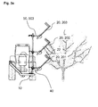
- a design of the base frame as an attachment, in particular a front attachment, for a tractor is particularly preferred and without further description in Fig. 3a and 3b indicated.
- Fig. 3b the possibility is further indicated to change the inclination of the main axis with respect to the vertical, so that further adjustment options for individual adaptation arise.
- Fig. 4 shows an elongate, about its longitudinal axis rotatable body 20 according to the present invention in detail.
- the body 20 is preferably a square steel, but may also be, for example, a polygonal or round steel.
- a hydraulic motor 28 is arranged, which can provide a shaft connection for a rotational movement of the body 20.
- On the outer circumferential surfaces of the body impact elements 22 are arranged. These are plastic cords, in the embodiment with about 2 mm in diameter and about 700 mm long, which are guided by two adjacent holes in a flat steel 24.
- the flat steel 24 is fastened to the body 20 by means of screws 26.
- a single impact element 22 is thus about 350 mm long.
- a plurality of such flat steel plastic cord assemblies are preferably disposed opposite to the representation on the entire circumference of the body 20.
Landscapes
- Life Sciences & Earth Sciences (AREA)
- Biodiversity & Conservation Biology (AREA)
- Ecology (AREA)
- Forests & Forestry (AREA)
- Environmental Sciences (AREA)
- Harvesting Machines For Specific Crops (AREA)
- Breeding Of Plants And Reproduction By Means Of Culturing (AREA)
- Catching Or Destruction (AREA)
- Medicines Containing Plant Substances (AREA)
- Mushroom Cultivation (AREA)
- Harvester Elements (AREA)
- Manipulator (AREA)
- Supports For Plants (AREA)
Priority Applications (2)
| Application Number | Priority Date | Filing Date | Title |
|---|---|---|---|
| PL07104875T PL1911345T3 (pl) | 2006-10-10 | 2007-03-26 | Regulacja ilości owoców na roślinach |
| SI200730909T SI1911345T1 (sl) | 2006-10-10 | 2007-03-26 | Reguliranje gostote sadeĺ˝ev sadnega drevja |
Applications Claiming Priority (1)
| Application Number | Priority Date | Filing Date | Title |
|---|---|---|---|
| DE102006048152 | 2006-10-10 |
Publications (2)
| Publication Number | Publication Date |
|---|---|
| EP1911345A1 true EP1911345A1 (fr) | 2008-04-16 |
| EP1911345B1 EP1911345B1 (fr) | 2012-02-08 |
Family
ID=38953682
Family Applications (1)
| Application Number | Title | Priority Date | Filing Date |
|---|---|---|---|
| EP07104875A Not-in-force EP1911345B1 (fr) | 2006-10-10 | 2007-03-26 | Régulation de la charge en fruit |
Country Status (7)
| Country | Link |
|---|---|
| EP (1) | EP1911345B1 (fr) |
| AT (1) | ATE544367T1 (fr) |
| DK (1) | DK1911345T3 (fr) |
| ES (1) | ES2382052T3 (fr) |
| PL (1) | PL1911345T3 (fr) |
| PT (1) | PT1911345E (fr) |
| SI (1) | SI1911345T1 (fr) |
Cited By (6)
| Publication number | Priority date | Publication date | Assignee | Title |
|---|---|---|---|---|
| ITBO20110480A1 (it) * | 2011-08-01 | 2013-02-02 | Massimo Mondini | Macchina per il dirado vegetale |
| CN103190299A (zh) * | 2013-04-01 | 2013-07-10 | 华南农业大学 | 悬挂式电动仿形疏花疏果机及其使用方法 |
| CN103190298A (zh) * | 2013-04-01 | 2013-07-10 | 华南农业大学 | 悬挂式液压仿形疏花疏果机及其使用方法 |
| CN112584698A (zh) * | 2018-07-17 | 2021-03-30 | 乔治·爱奥里斯 | 稀疏设备 |
| CN113597965A (zh) * | 2021-09-07 | 2021-11-05 | 广西壮族自治区农业科学院 | 一种促进沃柑早熟的种植方法 |
| IT202000020014A1 (it) * | 2020-08-11 | 2022-02-11 | Cl Mecc Snc Di Cavosi Lorenzo E Stefano | Dispositivo di diradamento fiorale delle piante da frutto” |
Citations (8)
| Publication number | Priority date | Publication date | Assignee | Title |
|---|---|---|---|---|
| US4819373A (en) | 1983-07-22 | 1989-04-11 | Gte Laboratories Incorporated | Method of thinning fruitlets or fruits of crops |
| JPH01309607A (ja) | 1988-06-07 | 1989-12-14 | Matsuyama Plow Mfg Co Ltd | 果樹園管理装置 |
| DE4103915A1 (de) * | 1991-02-08 | 1992-08-13 | Hermann Gessler | Verfahren und vorrichtung zum ausduennen von obstbaeumen |
| WO1998030078A2 (fr) | 1997-01-07 | 1998-07-16 | The University Of Arkansas | Materiel viticole, et systeme et procede de mecanisation de la viticulture |
| DE19713452A1 (de) | 1997-04-01 | 1998-10-08 | Hermann Gessler | Vorrichtung zum Ausdünnen von Obstbäumen |
| DE19932273A1 (de) | 1999-07-06 | 2001-01-11 | Saechsische Landesanstalt Fuer | Verfahren zur Fruchtausdünnung bei Obstbäumen |
| CA2045352C (fr) | 1990-06-26 | 2001-08-28 | Robert Jan Butsellar | Procede d'eclaircissement des fleurs d'arbres a drupes |
| KR20010083978A (ko) | 2000-02-23 | 2001-09-06 | 송희무 | 과수용 적과기 |
-
2007
- 2007-03-26 DK DK07104875.5T patent/DK1911345T3/da active
- 2007-03-26 PT PT07104875T patent/PT1911345E/pt unknown
- 2007-03-26 AT AT07104875T patent/ATE544367T1/de active
- 2007-03-26 PL PL07104875T patent/PL1911345T3/pl unknown
- 2007-03-26 ES ES07104875T patent/ES2382052T3/es active Active
- 2007-03-26 SI SI200730909T patent/SI1911345T1/sl unknown
- 2007-03-26 EP EP07104875A patent/EP1911345B1/fr not_active Not-in-force
Patent Citations (9)
| Publication number | Priority date | Publication date | Assignee | Title |
|---|---|---|---|---|
| US4819373A (en) | 1983-07-22 | 1989-04-11 | Gte Laboratories Incorporated | Method of thinning fruitlets or fruits of crops |
| JPH01309607A (ja) | 1988-06-07 | 1989-12-14 | Matsuyama Plow Mfg Co Ltd | 果樹園管理装置 |
| CA2045352C (fr) | 1990-06-26 | 2001-08-28 | Robert Jan Butsellar | Procede d'eclaircissement des fleurs d'arbres a drupes |
| DE4103915A1 (de) * | 1991-02-08 | 1992-08-13 | Hermann Gessler | Verfahren und vorrichtung zum ausduennen von obstbaeumen |
| DE4103915C2 (fr) | 1991-02-08 | 1992-11-12 | Hermann 7990 Friedrichshafen De Gessler | |
| WO1998030078A2 (fr) | 1997-01-07 | 1998-07-16 | The University Of Arkansas | Materiel viticole, et systeme et procede de mecanisation de la viticulture |
| DE19713452A1 (de) | 1997-04-01 | 1998-10-08 | Hermann Gessler | Vorrichtung zum Ausdünnen von Obstbäumen |
| DE19932273A1 (de) | 1999-07-06 | 2001-01-11 | Saechsische Landesanstalt Fuer | Verfahren zur Fruchtausdünnung bei Obstbäumen |
| KR20010083978A (ko) | 2000-02-23 | 2001-09-06 | 송희무 | 과수용 적과기 |
Cited By (7)
| Publication number | Priority date | Publication date | Assignee | Title |
|---|---|---|---|---|
| ITBO20110480A1 (it) * | 2011-08-01 | 2013-02-02 | Massimo Mondini | Macchina per il dirado vegetale |
| CN103190299A (zh) * | 2013-04-01 | 2013-07-10 | 华南农业大学 | 悬挂式电动仿形疏花疏果机及其使用方法 |
| CN103190298A (zh) * | 2013-04-01 | 2013-07-10 | 华南农业大学 | 悬挂式液压仿形疏花疏果机及其使用方法 |
| CN103190299B (zh) * | 2013-04-01 | 2014-09-24 | 华南农业大学 | 悬挂式电动仿形疏花疏果机及其使用方法 |
| CN112584698A (zh) * | 2018-07-17 | 2021-03-30 | 乔治·爱奥里斯 | 稀疏设备 |
| IT202000020014A1 (it) * | 2020-08-11 | 2022-02-11 | Cl Mecc Snc Di Cavosi Lorenzo E Stefano | Dispositivo di diradamento fiorale delle piante da frutto” |
| CN113597965A (zh) * | 2021-09-07 | 2021-11-05 | 广西壮族自治区农业科学院 | 一种促进沃柑早熟的种植方法 |
Also Published As
| Publication number | Publication date |
|---|---|
| EP1911345B1 (fr) | 2012-02-08 |
| PT1911345E (pt) | 2012-05-17 |
| SI1911345T1 (sl) | 2012-09-28 |
| ATE544367T1 (de) | 2012-02-15 |
| ES2382052T3 (es) | 2012-06-04 |
| PL1911345T3 (pl) | 2012-07-31 |
| DK1911345T3 (da) | 2012-05-21 |
Similar Documents
| Publication | Publication Date | Title |
|---|---|---|
| DE3486070T2 (de) | Schneidapparat zur verwendung in der landwirtschaft, dem weinbau und der baumgaertnerei. | |
| EP3091830B1 (fr) | Dispositif d'ébranchage d'arbres vivants | |
| EP3804484B1 (fr) | Dispositif d'entretien des plantes cultivées en rangées et des vignes | |
| EP1911345B1 (fr) | Régulation de la charge en fruit | |
| DE102007051989B4 (de) | Rebenvorschneider | |
| DE69800709T2 (de) | Maschine und Verfahren für die selektive Ernte von Beeren | |
| EP0407896B1 (fr) | Dispositif de travail du sol pour cultures en lignes | |
| DE60206954T2 (de) | Vorrichtung zum anordnen eines blumenstrausses | |
| DE3446281A1 (de) | Maschine zur ernte von kamillenbluetenkoepfchen | |
| DE4103915C2 (fr) | ||
| DE60303552T2 (de) | Verwendung eines Schneidzylinders, Schneidvorrichtung mit Schneidzylinder zum Formen einer Pflanze, Fahrzeug mit einer derartigen Schneidvorrichtung und Verwendung einer derartigen Schneidvorrichtung | |
| EP4282238A1 (fr) | Appareil de travail du sol | |
| DE19713452A1 (de) | Vorrichtung zum Ausdünnen von Obstbäumen | |
| DE2815466C2 (de) | Vorrichtung zum Beschneiden von Reben o.dgl. | |
| DE2452411A1 (de) | Vorrichtung zum ernten von weintrauben | |
| AT351312B (de) | Verfahren zum mechanisierten weinbau und rebenschneidmaschine | |
| DE102019108097B3 (de) | Vorrichtung zur Durchführung eines Verfahrens zur Spargelernte und Verfahren zur Spargelernte unter Verwendung der Vorrichtung | |
| DD273568A1 (de) | Drehegge | |
| EP2394504A1 (fr) | Dispositif de traction d'un véhicule de pulvérisation, notamment un tracteur | |
| DE4032489C2 (fr) | ||
| DE2731298A1 (de) | Verfahren zum mechanisierten weinbau und rebenschneidmaschine | |
| DE3614867A1 (de) | Maschine fuer die ernte von fruechten, beeren u.dgl. die von in reihe gepflanzten obstbaeumen und -straeuchern getragen werden | |
| DE9109887U1 (de) | Gerät zur Pflege hochrankender Pflanzen | |
| DE1176411B (de) | Bodenbearbeitungsgeraet | |
| DE102009006045A1 (de) | Mulch- und/oder Mähmaschine |
Legal Events
| Date | Code | Title | Description |
|---|---|---|---|
| PUAI | Public reference made under article 153(3) epc to a published international application that has entered the european phase |
Free format text: ORIGINAL CODE: 0009012 |
|
| AK | Designated contracting states |
Kind code of ref document: A1 Designated state(s): AT BE BG CH CY CZ DE DK EE ES FI FR GB GR HU IE IS IT LI LT LU LV MC MT NL PL PT RO SE SI SK TR |
|
| AX | Request for extension of the european patent |
Extension state: AL BA HR MK RS |
|
| 17P | Request for examination filed |
Effective date: 20080926 |
|
| AKX | Designation fees paid |
Designated state(s): AT BE BG CH CY CZ DE DK EE ES FI FR GB GR HU IE IS IT LI LT LU LV MC MT NL PL PT RO SE SI SK TR |
|
| 17Q | First examination report despatched |
Effective date: 20090423 |
|
| REG | Reference to a national code |
Ref country code: DE Ref legal event code: R079 Ref document number: 502007009243 Country of ref document: DE Free format text: PREVIOUS MAIN CLASS: A01G0003080000 Ipc: A43B0023140000 |
|
| RIC1 | Information provided on ipc code assigned before grant |
Ipc: A43B 23/14 20060101AFI20110721BHEP |
|
| GRAP | Despatch of communication of intention to grant a patent |
Free format text: ORIGINAL CODE: EPIDOSNIGR1 |
|
| GRAS | Grant fee paid |
Free format text: ORIGINAL CODE: EPIDOSNIGR3 |
|
| RIN1 | Information on inventor provided before grant (corrected) |
Inventor name: DAMEROW, LUTZ Inventor name: BLANKE, MICHAEL |
|
| DIN1 | Information on inventor provided before grant (deleted) | ||
| GRAA | (expected) grant |
Free format text: ORIGINAL CODE: 0009210 |
|
| RIN1 | Information on inventor provided before grant (corrected) |
Inventor name: BLANKE, MICHAEL Inventor name: DAMEROW, LUTZ |
|
| RIN1 | Information on inventor provided before grant (corrected) |
Inventor name: DAMEROW, LUTZ Inventor name: BLANKE, MICHAEL |
|
| RIN1 | Information on inventor provided before grant (corrected) |
Inventor name: DAMEROW, LUTZ Inventor name: BLANKE, MICHAEL |
|
| AK | Designated contracting states |
Kind code of ref document: B1 Designated state(s): AT BE BG CH CY CZ DE DK EE ES FI FR GB GR HU IE IS IT LI LT LU LV MC MT NL PL PT RO SE SI SK TR |
|
| REG | Reference to a national code |
Ref country code: GB Ref legal event code: FG4D Free format text: NOT ENGLISH |
|
| RIN1 | Information on inventor provided before grant (corrected) |
Inventor name: BLANKE, MICHAEL Inventor name: DAMEROW, LUTZ |
|
| REG | Reference to a national code |
Ref country code: AT Ref legal event code: REF Ref document number: 544367 Country of ref document: AT Kind code of ref document: T Effective date: 20120215 Ref country code: CH Ref legal event code: EP |
|
| REG | Reference to a national code |
Ref country code: DE Ref legal event code: R096 Ref document number: 502007009243 Country of ref document: DE Effective date: 20120405 |
|
| REG | Reference to a national code |
Ref country code: SE Ref legal event code: TRGR |
|
| REG | Reference to a national code |
Ref country code: NL Ref legal event code: T3 |
|
| REG | Reference to a national code |
Ref country code: PT Ref legal event code: SC4A Free format text: AVAILABILITY OF NATIONAL TRANSLATION Effective date: 20120504 |
|
| REG | Reference to a national code |
Ref country code: DK Ref legal event code: T3 |
|
| REG | Reference to a national code |
Ref country code: ES Ref legal event code: FG2A Ref document number: 2382052 Country of ref document: ES Kind code of ref document: T3 Effective date: 20120604 |
|
| REG | Reference to a national code |
Ref country code: GR Ref legal event code: EP Ref document number: 20120401006 Country of ref document: GR Effective date: 20120614 |
|
| LTIE | Lt: invalidation of european patent or patent extension |
Effective date: 20120208 |
|
| PG25 | Lapsed in a contracting state [announced via postgrant information from national office to epo] |
Ref country code: LT Free format text: LAPSE BECAUSE OF FAILURE TO SUBMIT A TRANSLATION OF THE DESCRIPTION OR TO PAY THE FEE WITHIN THE PRESCRIBED TIME-LIMIT Effective date: 20120208 Ref country code: IS Free format text: LAPSE BECAUSE OF FAILURE TO SUBMIT A TRANSLATION OF THE DESCRIPTION OR TO PAY THE FEE WITHIN THE PRESCRIBED TIME-LIMIT Effective date: 20120608 |
|
| REG | Reference to a national code |
Ref country code: PL Ref legal event code: T3 |
|
| REG | Reference to a national code |
Ref country code: IE Ref legal event code: FD4D |
|
| PG25 | Lapsed in a contracting state [announced via postgrant information from national office to epo] |
Ref country code: FI Free format text: LAPSE BECAUSE OF FAILURE TO SUBMIT A TRANSLATION OF THE DESCRIPTION OR TO PAY THE FEE WITHIN THE PRESCRIBED TIME-LIMIT Effective date: 20120208 |
|
| PG25 | Lapsed in a contracting state [announced via postgrant information from national office to epo] |
Ref country code: CY Free format text: LAPSE BECAUSE OF FAILURE TO SUBMIT A TRANSLATION OF THE DESCRIPTION OR TO PAY THE FEE WITHIN THE PRESCRIBED TIME-LIMIT Effective date: 20120208 |
|
| PG25 | Lapsed in a contracting state [announced via postgrant information from national office to epo] |
Ref country code: EE Free format text: LAPSE BECAUSE OF FAILURE TO SUBMIT A TRANSLATION OF THE DESCRIPTION OR TO PAY THE FEE WITHIN THE PRESCRIBED TIME-LIMIT Effective date: 20120208 Ref country code: RO Free format text: LAPSE BECAUSE OF FAILURE TO SUBMIT A TRANSLATION OF THE DESCRIPTION OR TO PAY THE FEE WITHIN THE PRESCRIBED TIME-LIMIT Effective date: 20120208 Ref country code: MC Free format text: LAPSE BECAUSE OF NON-PAYMENT OF DUE FEES Effective date: 20120331 Ref country code: CZ Free format text: LAPSE BECAUSE OF FAILURE TO SUBMIT A TRANSLATION OF THE DESCRIPTION OR TO PAY THE FEE WITHIN THE PRESCRIBED TIME-LIMIT Effective date: 20120208 Ref country code: IE Free format text: LAPSE BECAUSE OF FAILURE TO SUBMIT A TRANSLATION OF THE DESCRIPTION OR TO PAY THE FEE WITHIN THE PRESCRIBED TIME-LIMIT Effective date: 20120208 |
|
| REG | Reference to a national code |
Ref country code: CH Ref legal event code: PL |
|
| REG | Reference to a national code |
Ref country code: HU Ref legal event code: AG4A Ref document number: E014496 Country of ref document: HU |
|
| PG25 | Lapsed in a contracting state [announced via postgrant information from national office to epo] |
Ref country code: SK Free format text: LAPSE BECAUSE OF FAILURE TO SUBMIT A TRANSLATION OF THE DESCRIPTION OR TO PAY THE FEE WITHIN THE PRESCRIBED TIME-LIMIT Effective date: 20120208 |
|
| REG | Reference to a national code |
Ref country code: CH Ref legal event code: AECN Free format text: DAS PATENT IST AUFGRUND DES WEITERBEHANDLUNGSANTRAGS VOM 13.11.2012 REAKTIVIERT WORDEN. |
|
| PLBE | No opposition filed within time limit |
Free format text: ORIGINAL CODE: 0009261 |
|
| STAA | Information on the status of an ep patent application or granted ep patent |
Free format text: STATUS: NO OPPOSITION FILED WITHIN TIME LIMIT |
|
| 26N | No opposition filed |
Effective date: 20121109 |
|
| REG | Reference to a national code |
Ref country code: DE Ref legal event code: R097 Ref document number: 502007009243 Country of ref document: DE Effective date: 20121109 |
|
| PG25 | Lapsed in a contracting state [announced via postgrant information from national office to epo] |
Ref country code: BG Free format text: LAPSE BECAUSE OF FAILURE TO SUBMIT A TRANSLATION OF THE DESCRIPTION OR TO PAY THE FEE WITHIN THE PRESCRIBED TIME-LIMIT Effective date: 20120508 Ref country code: MT Free format text: LAPSE BECAUSE OF FAILURE TO SUBMIT A TRANSLATION OF THE DESCRIPTION OR TO PAY THE FEE WITHIN THE PRESCRIBED TIME-LIMIT Effective date: 20120208 |
|
| PG25 | Lapsed in a contracting state [announced via postgrant information from national office to epo] |
Ref country code: LU Free format text: LAPSE BECAUSE OF NON-PAYMENT OF DUE FEES Effective date: 20120326 |
|
| REG | Reference to a national code |
Ref country code: FR Ref legal event code: PLFP Year of fee payment: 9 |
|
| PGFP | Annual fee paid to national office [announced via postgrant information from national office to epo] |
Ref country code: PT Payment date: 20150324 Year of fee payment: 9 Ref country code: IT Payment date: 20150326 Year of fee payment: 9 Ref country code: NL Payment date: 20150319 Year of fee payment: 9 Ref country code: CH Payment date: 20150319 Year of fee payment: 9 Ref country code: DE Payment date: 20150320 Year of fee payment: 9 Ref country code: ES Payment date: 20150326 Year of fee payment: 9 Ref country code: DK Payment date: 20150319 Year of fee payment: 9 Ref country code: HU Payment date: 20150319 Year of fee payment: 9 |
|
| PGFP | Annual fee paid to national office [announced via postgrant information from national office to epo] |
Ref country code: GB Payment date: 20150319 Year of fee payment: 9 Ref country code: FR Payment date: 20150319 Year of fee payment: 9 Ref country code: SI Payment date: 20150225 Year of fee payment: 9 Ref country code: TR Payment date: 20150224 Year of fee payment: 9 Ref country code: PL Payment date: 20150317 Year of fee payment: 9 Ref country code: SE Payment date: 20150319 Year of fee payment: 9 Ref country code: AT Payment date: 20150320 Year of fee payment: 9 Ref country code: GR Payment date: 20150313 Year of fee payment: 9 Ref country code: LV Payment date: 20150218 Year of fee payment: 9 |
|
| PGFP | Annual fee paid to national office [announced via postgrant information from national office to epo] |
Ref country code: BE Payment date: 20150319 Year of fee payment: 9 |
|
| PG25 | Lapsed in a contracting state [announced via postgrant information from national office to epo] |
Ref country code: BE Free format text: LAPSE BECAUSE OF NON-PAYMENT OF DUE FEES Effective date: 20160331 |
|
| REG | Reference to a national code |
Ref country code: DE Ref legal event code: R119 Ref document number: 502007009243 Country of ref document: DE |
|
| REG | Reference to a national code |
Ref country code: DK Ref legal event code: EBP Effective date: 20160331 |
|
| REG | Reference to a national code |
Ref country code: CH Ref legal event code: PL |
|
| REG | Reference to a national code |
Ref country code: SE Ref legal event code: EUG |
|
| REG | Reference to a national code |
Ref country code: AT Ref legal event code: MM01 Ref document number: 544367 Country of ref document: AT Kind code of ref document: T Effective date: 20160326 |
|
| REG | Reference to a national code |
Ref country code: NL Ref legal event code: MM Effective date: 20160401 |
|
| GBPC | Gb: european patent ceased through non-payment of renewal fee |
Effective date: 20160326 |
|
| PG25 | Lapsed in a contracting state [announced via postgrant information from national office to epo] |
Ref country code: LV Free format text: LAPSE BECAUSE OF NON-PAYMENT OF DUE FEES Effective date: 20160326 Ref country code: SE Free format text: LAPSE BECAUSE OF NON-PAYMENT OF DUE FEES Effective date: 20160327 Ref country code: PT Free format text: LAPSE BECAUSE OF NON-PAYMENT OF DUE FEES Effective date: 20160926 |
|
| REG | Reference to a national code |
Ref country code: SI Ref legal event code: KO00 Effective date: 20161121 Ref country code: FR Ref legal event code: ST Effective date: 20161130 |
|
| PG25 | Lapsed in a contracting state [announced via postgrant information from national office to epo] |
Ref country code: DE Free format text: LAPSE BECAUSE OF NON-PAYMENT OF DUE FEES Effective date: 20161001 Ref country code: FR Free format text: LAPSE BECAUSE OF NON-PAYMENT OF DUE FEES Effective date: 20160331 Ref country code: HU Free format text: LAPSE BECAUSE OF NON-PAYMENT OF DUE FEES Effective date: 20160327 Ref country code: GB Free format text: LAPSE BECAUSE OF NON-PAYMENT OF DUE FEES Effective date: 20160326 Ref country code: NL Free format text: LAPSE BECAUSE OF NON-PAYMENT OF DUE FEES Effective date: 20160401 Ref country code: CH Free format text: LAPSE BECAUSE OF NON-PAYMENT OF DUE FEES Effective date: 20160331 Ref country code: LI Free format text: LAPSE BECAUSE OF NON-PAYMENT OF DUE FEES Effective date: 20160331 |
|
| REG | Reference to a national code |
Ref country code: GR Ref legal event code: ML Ref document number: 20120401006 Country of ref document: GR Effective date: 20161006 |
|
| PG25 | Lapsed in a contracting state [announced via postgrant information from national office to epo] |
Ref country code: AT Free format text: LAPSE BECAUSE OF NON-PAYMENT OF DUE FEES Effective date: 20160326 Ref country code: IT Free format text: LAPSE BECAUSE OF NON-PAYMENT OF DUE FEES Effective date: 20160326 Ref country code: SI Free format text: LAPSE BECAUSE OF NON-PAYMENT OF DUE FEES Effective date: 20160327 Ref country code: GR Free format text: LAPSE BECAUSE OF NON-PAYMENT OF DUE FEES Effective date: 20161006 |
|
| PG25 | Lapsed in a contracting state [announced via postgrant information from national office to epo] |
Ref country code: DK Free format text: LAPSE BECAUSE OF NON-PAYMENT OF DUE FEES Effective date: 20160331 |
|
| PG25 | Lapsed in a contracting state [announced via postgrant information from national office to epo] |
Ref country code: PL Free format text: LAPSE BECAUSE OF NON-PAYMENT OF DUE FEES Effective date: 20160326 |
|
| PG25 | Lapsed in a contracting state [announced via postgrant information from national office to epo] |
Ref country code: ES Free format text: LAPSE BECAUSE OF NON-PAYMENT OF DUE FEES Effective date: 20160327 |
|
| REG | Reference to a national code |
Ref country code: ES Ref legal event code: FD2A Effective date: 20181205 |
|
| PG25 | Lapsed in a contracting state [announced via postgrant information from national office to epo] |
Ref country code: TR Free format text: LAPSE BECAUSE OF NON-PAYMENT OF DUE FEES Effective date: 20160326 |