EP1911882A2 - Système de fabrication d'un revêtement pour un toit, un sol ou analogue, sur lequel on peut marcher ou rouler. - Google Patents
Système de fabrication d'un revêtement pour un toit, un sol ou analogue, sur lequel on peut marcher ou rouler. Download PDFInfo
- Publication number
- EP1911882A2 EP1911882A2 EP20070020138 EP07020138A EP1911882A2 EP 1911882 A2 EP1911882 A2 EP 1911882A2 EP 20070020138 EP20070020138 EP 20070020138 EP 07020138 A EP07020138 A EP 07020138A EP 1911882 A2 EP1911882 A2 EP 1911882A2
- Authority
- EP
- European Patent Office
- Prior art keywords
- joint
- profiles
- profile
- spacers
- spacer
- Prior art date
- Legal status (The legal status is an assumption and is not a legal conclusion. Google has not performed a legal analysis and makes no representation as to the accuracy of the status listed.)
- Withdrawn
Links
Images


Classifications
-
- E—FIXED CONSTRUCTIONS
- E01—CONSTRUCTION OF ROADS, RAILWAYS, OR BRIDGES
- E01C—CONSTRUCTION OF, OR SURFACES FOR, ROADS, SPORTS GROUNDS, OR THE LIKE; MACHINES OR AUXILIARY TOOLS FOR CONSTRUCTION OR REPAIR
- E01C11/00—Details of pavings
- E01C11/02—Arrangement or construction of joints; Methods of making joints; Packing for joints
- E01C11/04—Arrangement or construction of joints; Methods of making joints; Packing for joints for cement concrete paving
- E01C11/12—Packing of metal and plastic or elastic materials
- E01C11/126—Joints with only metal and prefabricated packing or filling
-
- E—FIXED CONSTRUCTIONS
- E04—BUILDING
- E04D—ROOF COVERINGS; SKY-LIGHTS; GUTTERS; ROOF-WORKING TOOLS
- E04D11/00—Roof covering, as far as not restricted to features covered by only one of groups E04D1/00 - E04D9/00; Roof covering in ways not provided for by groups E04D1/00 - E04D9/00, e.g. built-up roofs, elevated load-supporting roof coverings
- E04D11/02—Build-up roofs, i.e. consisting of two or more layers bonded together in situ, at least one of the layers being of watertight composition
-
- E—FIXED CONSTRUCTIONS
- E04—BUILDING
- E04F—FINISHING WORK ON BUILDINGS, e.g. STAIRS, FLOORS
- E04F15/00—Flooring
- E04F15/12—Flooring or floor layers made of masses in situ, e.g. seamless magnesite floors, terrazzo gypsum floors
- E04F15/14—Construction of joints, e.g. dividing strips
Definitions
- the invention relates to a system for producing a covering for walk-on and / or passable roof surfaces, soil coverings or the like, in particular for parking roofs. Furthermore, the invention relates to spacers and joint profiles that are used in the system.
- the covering is preferably used in connection with park roofs, but is also suitable for driveways, sidewalks, terraces or the like, so earth covers in general. A use on other roof surfaces, such as balconies, etc. comes into consideration.
- gauges are used which are positioned in the region of joints to be formed and which are removed again after the introduction and at least partial hardening of the concrete, see, for example DE-A-19 08 142 ,
- Object of the present invention is to provide an improved system for the production of a covering for walk-in and / or passable roofs, soil cover or the like.
- the joint profiles are positioned in the area of the joint to be formed during the production of the covering, in order to prevent the penetration of fresh concrete into the joint area. After filling the concrete, the joint profiles remain in the area of the joint and bind at least partially into the concrete.
- the joint profiles are not removed after setting the concrete, but remain as permanent formwork in the concrete or in the area of the joint.
- the joint can thereby have a more complex geometry than in conventional manufacturing processes. In addition, eliminates a single operation, since the joint profiles are not removed.
- the joint profiles are connected to each other in particular circumferential closed frame, wherein the fresh concrete is filled in each case in the frame thus formed, for the production of preferably large-sized concrete slabs with preferably circumferential joint.
- the joint profiles thus serve to produce the mold for the concrete slabs on the one hand and for the production of the joint on the other.
- the joint profiles are positioned on both sides of the joint to be formed, in particular in such a way that the joint has a symmetrical cross section. Furthermore, it is provided that the mutual joint profiles are secured by insertable between the joint profiles separate spacers in position, the spacers are removed after the at least partial setting of the concrete. Alternatively, the spacers can remain in the joints.
- the joint profiles are formed in cross-section such that the joint in the region of an upper side of the covering has a larger cross-sectional width than in a lower region of the joint so that a joint sealable in the region of the upper side of the covering can be supported on the underside by the joint profiles ,
- the joint sealing profile is substantially flush with the top of the concrete slabs.
- joint profiles limit upright side surfaces of the concrete slabs and form in this way a formwork for the individual elements of the covering.
- the joint profiles extend from an upper side of the lining over at least the major part of the height of the concrete slabs in the direction of an underside thereof.
- the joint profiles may be formed bent several times, such that an upper portion of the joint for receiving the joint-sealing profile has a width which corresponds approximately to the width of the joint-sealing profile, or preferably has a slightly narrower width than the joint-sealing profile.
- the joint profiles are then angled projecting to the interior of the joint at the top, to form transverse support surfaces for a bottom of the jointing profile. In this way, the jointing profile is safely supported on the underside, without further action must be taken. In particular, it is not necessary to fill the lower part of the joint, so that, as a result, the entire joint width in the lower region is available for dissipating moisture.
- joint profiles of a joint run in the upper region of the same upright, preferably in cross section parallel to each other.
- the joint profiles following the projecting to the interior of the joint angled region continue to be angled such that the joint has a lower portion with a smaller width than in the upper region.
- the joint profiles may be formed such that the lower region of the joint preferably extends continuously to at least near the underside of the concrete slabs.
- the joint profiles run upright in the lower region of the joint, preferably parallel to one another in cross section.
- the joint profiles can also extend in the area of the top of the concrete slabs, to protect the between top and upright Side surfaces of the concrete slabs formed edges.
- the joint profiles extend in a horizontally angled region at the top of the concrete slabs.
- the joint profiles are angled in the area of the upper side such that a free end of the joint profile projects downward into the concrete or binds it.
- the joint profiles extend in a horizontally angled region at least near the underside of the concrete slabs or in the region thereof. In this way, a footprint for the joint profiles is created, whereby the installation can be facilitated.
- the joint profiles in the region or in the vicinity of the underside of the concrete slabs are then bent in such a way that a free end of the joint profile protrudes upward into the concrete or binds.
- the joint profiles can form a preferably circumferential and closed frame as formwork for the concrete slabs.
- the frame can be formed from floor plan profiles that are rectilinear in plan, which are arranged in the region of the upright side surfaces of the concrete slabs.
- special connecting profiles can be provided for connecting longitudinally adjoining joint profiles, which have substantially the same shape as the straight joint profiles, but different dimensions, so that the connection profiles in the joint area of the joint profiles fit positively against these and can be connected to them.
- the positionable between the mutual joint profiles spacers have a special shape, which preferably corresponds to the joint cross-section between the mutual joint profiles, so that the spacers lie laterally positively against the joint profiles.
- the spacers have interlocking elements, which can be arranged laterally projecting, in particular on both sides of the spacers and which are designed such that they each engage behind the adjacent joint profiles.
- the interlocking elements are arranged below an upper side of the respective spacer and in particular directed downwards.
- the joint profiles have recordings for the hooking elements.
- the receptacles are preferably recesses or openings, for example in the form of oblong holes.
- the hooking elements engage in the recesses.
- the receptacles for the Verhakungs institute are preferably arranged in the projecting angled region of the joint profiles, ie below the upper portion of the joint profile.
- the width of the receptacle extends over the entire protruding angled region of the joint profile.
- the spacers preferably have a wider cross section in their upper portion than in their lower portion, the hooking elements extending downwardly from the upper portion, in particular such that lateral outer surfaces of the upper portion extend in respective same plane as outer surfaces of the interlocking members.
- the outer surfaces of the upper portion on the one hand and the outer surfaces of the Verhakungs comprise other hand, go over without transition into each other.
- a downwardly open gap is formed between the respective hooking element and the lower portion of the spacer, the width of which in particular corresponds to the thickness of the joint profile at this point, wherein the joint profile at least partially hineinerstreckt into the gap.
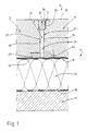
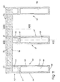
- the embodiment shown in the figures is a covering 10 for a parking roof 11.
- the covering 10 consists of several concrete slabs 12, which are each laid at a distance from each other on the parking roof 11. Between the concrete slabs 12 joints 13 are formed. Preferably, the joints 13 have a constant width and are arranged circumferentially around each concrete slab 12 around.
- the joints 13 preferably extend over the entire height of the concrete slabs 12 between the respective mutually facing upright side surfaces 14 adjacent concrete slabs 12.
- the joints thus preferably extend continuously from a top 15 to the bottom 16 of the concrete slabs 12th
- the covering 10 described below in detail of concrete slabs 12 with joint 13 will be described with reference to a parking roof 11.
- the pad 10 is basically suitable for other purposes, such. As a coating for roads, sidewalks, terraces or the like, so for soil coverings in general. Furthermore, the covering can of course also be laid on balconies or other roof surfaces.
- a lower raw ceiling 17 of a parking garage is present.
- the raw ceiling 17 is usually made of concrete and is provided on the top with a horizontal Notabdichtung 18.
- Above the emergency seal follows a layer of thermal insulation 19, which in turn is provided with a double-layered seal 20.
- a double-layered seal 20 As far as it concerns the usual structure of a parking roof.
- the covering 10 On the upper seal 20 of the covering 10 is made of concrete slabs 12. This takes place in cast-in-situ construction, ie on site at the construction site.
- the covering to be created 10 is first divided into individual concrete slabs 12 and thereby determines the location of the high points and low points in order to derive the resulting surface water can.
- joint profiles 21 are placed in the field of joints to be produced 13 special joint profiles 21 are placed.
- the joint profiles 21 rest on the underside on a foam strip 22, which serves to compensate for height differences.
- a foam strip 22 which serves to compensate for height differences.
- other elastically deformable materials can be used.
- the joint profiles 21 may also be directly on the seal 20.
- the joint profiles 21 serve as a formwork for the concrete slabs 12.
- the joint profiles 21 are connected to preferably closed, surrounding frame, each surrounding a concrete slab 12 to be produced. Concrete is then poured into these frames until the concrete 4 on the upper side is substantially flush with the joint profiles 21. Too much filled concrete 45 can optionally be deducted.
- the joint profiles 21 remain in their position, ie, they are not removed after the setting or partial setting of the concrete 45.
- the joint profiles 21 are used so to speak as a lost formwork.
- Fig. 1 come on both sides of the joint 13 identical joint profiles 21 are used, which are, however, mirror-inverted, so that the joint 13 has a symmetrical cross-section.
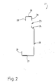
- the joint profile 21 shown in Fig. 1 on the left side of the joint 13 is shown in Fig. 2 on a larger scale and is described in detail below:
- the joint profile 21 consists of an upper, upright portion 23, a thereto On the underside adjoining oblique portion 24 and a lower side subsequent thereto lower, upright portion 25.
- At the upper portion 23 and the lower portion 25 close in each case two horizontal portions 26, 27 at.
- the free ends 28, 29 are each angled at 90 ° to the horizontal sections 26, 27 so that they face the interior of the concrete slab 12.
- the lower horizontal portion 27 of the joint profile 21 serves as a footprint.
- the adjoining lower portion 25 extends upward, preferably vertically and limits the concrete slab 12 and the joint 13 in a lower joint portion 30.
- this lower joint portion 30 is the Fugue formed with a small width.
- the lower portion 25 of the joint profile 21 to the joint 13 is arranged flush with the foam strip 22, so that the lower joint portion 30 extends with a constant width over the lower portion 25 and the foam strip 22.
- the width of the joint is increased, namely in the direction of an upper joint portion 31, which is bounded laterally by the upper upright portion 23 of the joint profile 21.
- the adjoining horizontally directed portion 26 extends along the top 15 of the concrete slabs 12.
- the free end 28 extends from the top 15 of the concrete slab 12 to the interior thereof and serves to anchor the joint profile 21 in the concrete.
- the course of the upright side surfaces 14 of the concrete slabs 12 is formed by the sections 23, 24 and 25 of the joint profile.
- the peripheral upper edges of the concrete slab 12 are protected by the angled course of the upper portion 23 and the horizontal portion 26.
- the joint profile 21 thus also serves to reinforce the upper edges of the concrete slabs.
- a special feature with regard to the formation of the joints 13 is not only that the joint profiles 21 remain in the concrete, but also in that the upper joint portion 31 is adapted to receive a joint sealing profile 32.
- the joint-sealing profile 32 preferably has a greater width than the upper joint section 31, so that it can be inserted into the upper joint section 31 under sealing engagement with the upright upper sections 23 of the mutual joint profiles 21. This is preferably done such that an upper side of the joint-sealing profile 32 runs essentially flush with the upper side 15 of the concrete slabs 12.
- the joint-sealing profile 32 is supported by the oblique sections 24 of the mutual joint profiles 21, so that the joint-sealing profile 32 can not be pressed into the lower joint section 30.
- the oblique portions 24 of the jointing profiles 32 thus serve as a support for the jointing profile 32. Due to the predetermined by the joint profiles 21 shape of the joint 13 are essentially no further operations in the region of the joint 13 to do after concreting the concrete slabs 12 to the final Shape of the joint 13 produce. In particular, the known from the prior art widening of the joint 13 in the region of the top 15 of the concrete slabs 12 omitted. The lower joint portion 30 also remains free and does not need to be filled to create a support for the jointing profile 32. The preparation of the joint 13 is thus carried out in a few operations and therefore correspondingly inexpensive.
- the joint profiles 21 are preferably made of a stainless steel or sheet metal, such as V2A.
- the sheet thickness can be for example 1 mm.
- the joint profiles 21 can also be made of other materials, such as non-metallic building materials, such as plastic, composite materials, etc.
- the free ends 28, 29 each protrude into the concrete slab 12 by 10 mm.
- the upper horizontal portion 26 may have a width of 16 mm.
- the upper portion 23 may have a height of 25 mm.
- the inclined section 24, which in the embodiment shown by 60 ° to the upper portion. 23 is angled formed.
- the lower portion 25 projects from the upper portion 23 about 6 mm to the interior of the joint and extends over a height of 62 mm to 82 mm.
- the lower footprint of the lower horizontal portion 27 may be 30 mm. If one assumes a horizontal width of the lower one Joint section 30 of about 6 mm, the width of the upper joint portion 31 is at a horizontal extent of the inclined portions 24 of 6 mm in total 18 mm.
- the joint sealing profile 32 is preferably made of an elastic plastic. As described above, the joint-sealing profile 32 has an excess width, so that it has to be squeezed or hammered into the upper joint section 31. For this purpose, the jointing profile 32 on both sides protruding sealing lips 33 and inner hollow chambers 34th
- the joint profiles 21 are placed so that they form a preferably closed, circumferential frame for each concrete slab 12.
- the joint profiles 21 thus extend along the four upright side surfaces 14.
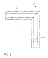
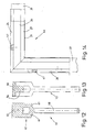
- the frames are preferably formed in several parts and consist of substantially rectilinear joint profiles 21 in the region of the upright side surfaces 14 and angled corner profiles 35 in the area Grundrissecken the concrete slab 12.
- the straight joint profiles 21 and the corner profiles 35 are connected together in a joint area 36.
- a shock profile 37 is used, which is shown in Fig. 6.
- the impact profile 37 has the same shape as the straight joint profiles 13 and the corner profile 35, but has smaller dimensions, so that it can be inserted on the side facing away from the joint 13 in the joint profile 21 on one side and the corner profile 35 on the other side substantially form-fitting manner , Joint profile 21 and corner profile 35 thus butt against each other.
- the joint 36 is concealed on the side remote from the joint 13 by the impact profile 37.
- a provided in the joint profile 21 or corner profile 35 bore 38 see Fig. 2
- these can be connected to the impact profile 37, for example by screws, rivets, etc.
- the individual sections of the shock profile 37 correspond to those of the joint profile 21, so far as for the individual sections corresponding reference numerals are used.
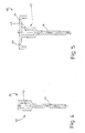
- FIGS. 4 and 5 show spacers 39, 40, which are used in the manufacture of concrete slabs 12. Looking together at FIGS. 1 and 4 or 5, it can be seen that the spacers 39, 40 are intended to be placed between the joint profiles 21.
- the shape of the spacers 39, 40 therefore corresponds completely (FIG. 4) or substantially (FIG. 5) to the cross section of the joint 13.
- Both spacers 39, 40 have a lower web 41, which has the same shape and dimensions as the lower one Joint section 30 corresponds.
- This is followed on the upper side by a chamber 42 whose outer shape and dimensions correspond to the upper joint section 31.
- the chambers 42 also have a central cavity 43, which brings a saving of material without the stability of the spacers 39, 40 suffers.
- the spacers may of course be formed without the chamber 42.
- the spacer 40 shown in Fig. 5 differs from the spacer 39 shown in FIG. 4 by two laterally projecting webs 44 which are angled.
- the webs 44 abut the horizontal portions 26 and the free ends 28 of the mutual joint profiles 21, so that the spacers 39 are held in position.
- the webs 44 thus serve as quasi Verhakungsmaschine.
- the spacers 40 or their webs 44 are formed such that the spacers 40 can be connected to the joint profiles 21 in a latching manner.
- the spacers 39, 40 are preferably made of plastic, but may also be made of other materials.
- the spacers 39, 40 are inserted into the joint 13 after installation of the joint profiles 21.
- the spacers 39, 40 have only a small depth in the longitudinal direction of the joint 13 and are arranged distributed at a distance from one another over the longitudinal direction of the joint 13. This is done for the purpose that the established frame from the joint profiles 21 can not move against each other, so that the joint 13 always has a constant width. In addition, it can be prevented in this way that the joint profiles 21 deform during the filling of the concrete by the concrete pressure and thus arise irregular joint progressions.
- FIGS. 7 to 14 will be explained below. As far as possible and objectively required, the reference numbers of the preceding embodiments are adopted.
- a joint profile 46 of FIG. 7 is consistent in its dimensions and in its shape with the joint profile 21 of FIG. The only difference is a recess 47 in the region of the oblique section 24.
- the recess 47 is formed as a slot with a larger dimension perpendicular to the image plane.
- the recess 47 extends up to the upper portion 23 and the lower portion 25 zoom.
- a plurality of recesses 47 may be present.
- a spacer 48 shown in FIGS. 8 and 9 is formed similarly to the spacer 39.
- the spacer 48 has hooking elements 49 which are directed downwards from the (upper) chamber 42 and parallel to the (lower) web 41, so that the chamber 42 and hooking elements 49 each have a common continuous, upright side surface 50.
- the width of the gap 51 corresponds approximately to the thickness of the lower portion 25 of the joint profile 46.
- the interlocking elements 49 are short webs or studs with rounded ends and extend from the chamber 42 downwards by about one third of the chamber height. Other length dimensions are possible.
- the spacer 48 completely fills the gap between the two joint profiles 46, at least in the directions of the image plane.
- the side surfaces 50 come to rest on the upper sections 23, as does the web 41 on the lower sections 25.
- an upper side 52 of the spacer 48 is flush with the horizontal sections 26 of the joint profiles 46.
- Fig. 14 shows a corner profile 53 corresponding to the corner profile 35 in Fig. 3, but with the recesses 47 in the region of the oblique sections 24. Dashed lines are still shock profiles 37 as a connector with joint profiles not shown 46 or 21st
- a special feature is the spacer 54 shown in FIGS. 11 to 13.
- the spacers 48 are only selectively placed between the joint profiles 46, corresponding to the arrangement of the recesses 47. In the longitudinal direction of the joints formed between the joint profiles 46 so arise between the spacers 48th open joint areas. So that they are not filled with concrete during the production of the concrete lining, the spacer 54 is provided, which is placed between two longitudinally longitudinal direction of the gap 48. Formed is the Spacer by a T-profile extending in the longitudinal direction of the joint, see FIG. 13, with upper transverse web 55 and subsequent longitudinal web 56 (in each case hatched in FIG. 13).
- the T-profile is provided with integrated spacers 57, which are modeled or similar to the spacer 39 shown in FIG. 4.
- the integrated spacers 57 have in the region of the web 49 a large-area recess 58 for saving material and weight.
- the web 41 is therefore formed only by two narrow downwardly directed end walls 59 and a bottom wall 60 connecting them, wherein the end walls 59 connect to obliquely directed walls 61 of the chamber 42 at the top.
- a cavity 62 is not quite as high as the cavity 43 in Fig. 4. Rather, the cavity 62 ends at the top of the longitudinal web 56 which is widened in the region of the integrated spacer 57 to the full width of the crosspiece 55 and there therefore is provided with the reference numeral 63.
Landscapes
- Engineering & Computer Science (AREA)
- Architecture (AREA)
- Civil Engineering (AREA)
- Structural Engineering (AREA)
- Road Paving Structures (AREA)
Applications Claiming Priority (1)
| Application Number | Priority Date | Filing Date | Title |
|---|---|---|---|
| DE200620015909 DE202006015909U1 (de) | 2006-10-13 | 2006-10-13 | System zur Herstellung eines Belags für begeh- und/oder befahrbare Dachflächen, Erdreichabdeckungen o.dgl. |
Publications (1)
| Publication Number | Publication Date |
|---|---|
| EP1911882A2 true EP1911882A2 (fr) | 2008-04-16 |
Family
ID=37670511
Family Applications (1)
| Application Number | Title | Priority Date | Filing Date |
|---|---|---|---|
| EP20070020138 Withdrawn EP1911882A2 (fr) | 2006-10-13 | 2007-10-15 | Système de fabrication d'un revêtement pour un toit, un sol ou analogue, sur lequel on peut marcher ou rouler. |
Country Status (2)
| Country | Link |
|---|---|
| EP (1) | EP1911882A2 (fr) |
| DE (1) | DE202006015909U1 (fr) |
Cited By (3)
| Publication number | Priority date | Publication date | Assignee | Title |
|---|---|---|---|---|
| DE202013103285U1 (de) | 2013-07-22 | 2013-09-12 | Poburski Futura Gmbh | Dilatations- und Kontraktionsfugen bei Verkehrsflächen aus Beton |
| DE102013107817A1 (de) | 2013-07-22 | 2015-01-22 | Poburski Futura Gmbh | Dilatations- und Kontraktionsfugen bei Verkehrsflächen aus Beton |
| EP2829657A1 (fr) | 2013-07-22 | 2015-01-28 | Poburski Futura GmbH | Joint de dilatation et de contraction pour des surfaces de voies de circulation en béton |
-
2006
- 2006-10-13 DE DE200620015909 patent/DE202006015909U1/de not_active Expired - Lifetime
-
2007
- 2007-10-15 EP EP20070020138 patent/EP1911882A2/fr not_active Withdrawn
Cited By (3)
| Publication number | Priority date | Publication date | Assignee | Title |
|---|---|---|---|---|
| DE202013103285U1 (de) | 2013-07-22 | 2013-09-12 | Poburski Futura Gmbh | Dilatations- und Kontraktionsfugen bei Verkehrsflächen aus Beton |
| DE102013107817A1 (de) | 2013-07-22 | 2015-01-22 | Poburski Futura Gmbh | Dilatations- und Kontraktionsfugen bei Verkehrsflächen aus Beton |
| EP2829657A1 (fr) | 2013-07-22 | 2015-01-28 | Poburski Futura GmbH | Joint de dilatation et de contraction pour des surfaces de voies de circulation en béton |
Also Published As
| Publication number | Publication date |
|---|---|
| DE202006015909U1 (de) | 2007-01-04 |
Similar Documents
| Publication | Publication Date | Title |
|---|---|---|
| DE19722349A1 (de) | Untergrundseitig anzuklebendes Profil zum Abschluß von verlegten Keramikplatten oder dergleichen | |
| DE19962812A1 (de) | Verfahren und Vorrichtung zum Schließen von Fugen | |
| AT410567B (de) | Deckenrandschalenelement sowie verwendung desselben | |
| EP1658405B1 (fr) | Element de coffrage isolant notamment destine a la fabrication du coffrage d'une dalle de plancher d'un immeuble et procede de fabrication d'un tel coffrage | |
| EP0194435A2 (fr) | Dispositif pour la réalisation de joints d'expansion dans des surfaces de plancher ou de béton | |
| DE19801123B4 (de) | Fundamentaufbau sowie Sockelelement für die Verwendung darin | |
| DE10262101B4 (de) | Dämmstoffplatte | |
| EP0849412A2 (fr) | Panneau en bois | |
| EP1911882A2 (fr) | Système de fabrication d'un revêtement pour un toit, un sol ou analogue, sur lequel on peut marcher ou rouler. | |
| EP4392615B1 (fr) | Structure souterraine pour le guidage d'une conduite | |
| EP1083269A2 (fr) | Aides pour la pose de revêtements en plaques en position surélevée ou ventilée | |
| DE29720122U1 (de) | System zur Herstellung von Stelzen für Belagsaufbauten aus Platten auf Terrassen, Balkonen o.dgl. | |
| DE202013103285U1 (de) | Dilatations- und Kontraktionsfugen bei Verkehrsflächen aus Beton | |
| DE3326856A1 (de) | Bauelement zur herstellung von gebaeudewaenden aus beton, insbesondere zur herstellung von kellerwaenden | |
| EP1736605B1 (fr) | Chassis de balcon, balcon et procédé de réalisation d'un balcon préfabriqué | |
| DE69927676T2 (de) | Modulares element für wände oder doppelwände für trockenmontage | |
| DE2612048A1 (de) | Fertigteilebauwerk in modulbauweise | |
| DE102022131325B4 (de) | Anordnung von Schalungselementen | |
| DE102005032566A1 (de) | Verfahren zur Herstellung einer Fuge in Betonbelägen und Belag für begeh- und/oder befahrbare Dachflächen, insbesondere Parkdächer | |
| DE29709378U1 (de) | Untergrundseitig anzuklebendes Profil zum Abschluß von verlegten Keramikplatten o.dgl. | |
| EP0166719A2 (fr) | Joint d'étanchéité profilé | |
| DE10013613A1 (de) | Betonpflasterstein | |
| EP2829657B1 (fr) | Joint de dilatation et de contraction pour des surfaces de voies de circulation en béton | |
| DE2109911A1 (de) | Mit Bekleidungsplatten ausgerüstete Bauplatte aus Schaumkunststoff, insbesondere Außenwandplatte | |
| DE102013107817A1 (de) | Dilatations- und Kontraktionsfugen bei Verkehrsflächen aus Beton |
Legal Events
| Date | Code | Title | Description |
|---|---|---|---|
| PUAI | Public reference made under article 153(3) epc to a published international application that has entered the european phase |
Free format text: ORIGINAL CODE: 0009012 |
|
| AK | Designated contracting states |
Kind code of ref document: A2 Designated state(s): AT BE BG CH CY CZ DE DK EE ES FI FR GB GR HU IE IS IT LI LT LU LV MC MT NL PL PT RO SE SI SK TR |
|
| AX | Request for extension of the european patent |
Extension state: AL BA HR MK RS |
|
| STAA | Information on the status of an ep patent application or granted ep patent |
Free format text: STATUS: THE APPLICATION IS DEEMED TO BE WITHDRAWN |
|
| 18D | Application deemed to be withdrawn |
Effective date: 20100504 |