EP1912014A2 - Base de dispoitif de visualisation incluant un limiteur de couple et limiteur de couple - Google Patents
Base de dispoitif de visualisation incluant un limiteur de couple et limiteur de couple Download PDFInfo
- Publication number
- EP1912014A2 EP1912014A2 EP07253980A EP07253980A EP1912014A2 EP 1912014 A2 EP1912014 A2 EP 1912014A2 EP 07253980 A EP07253980 A EP 07253980A EP 07253980 A EP07253980 A EP 07253980A EP 1912014 A2 EP1912014 A2 EP 1912014A2
- Authority
- EP
- European Patent Office
- Prior art keywords
- support sections
- driven gear
- torque limiter
- rotating member
- sections
- Prior art date
- Legal status (The legal status is an assumption and is not a legal conclusion. Google has not performed a legal analysis and makes no representation as to the accuracy of the status listed.)
- Granted
Links
- 230000002093 peripheral effect Effects 0.000 claims abstract description 80
- 230000002401 inhibitory effect Effects 0.000 claims abstract description 38
- 230000005540 biological transmission Effects 0.000 claims abstract description 28
- 239000011347 resin Substances 0.000 description 16
- 229920005989 resin Polymers 0.000 description 16
- 239000004973 liquid crystal related substance Substances 0.000 description 12
- 239000002184 metal Substances 0.000 description 10
- 229910000831 Steel Inorganic materials 0.000 description 8
- 239000010959 steel Substances 0.000 description 8
- 239000012530 fluid Substances 0.000 description 5
- 230000006835 compression Effects 0.000 description 2
- 238000007906 compression Methods 0.000 description 2
- 238000010586 diagram Methods 0.000 description 2
- 238000009877 rendering Methods 0.000 description 1
- 238000007789 sealing Methods 0.000 description 1
Images




Classifications
-
- F—MECHANICAL ENGINEERING; LIGHTING; HEATING; WEAPONS; BLASTING
- F16—ENGINEERING ELEMENTS AND UNITS; GENERAL MEASURES FOR PRODUCING AND MAINTAINING EFFECTIVE FUNCTIONING OF MACHINES OR INSTALLATIONS; THERMAL INSULATION IN GENERAL
- F16M—FRAMES, CASINGS OR BEDS OF ENGINES, MACHINES OR APPARATUS, NOT SPECIFIC TO ENGINES, MACHINES OR APPARATUS PROVIDED FOR ELSEWHERE; STANDS; SUPPORTS
- F16M11/00—Stands or trestles as supports for apparatus or articles placed thereon ; Stands for scientific apparatus such as gravitational force meters
- F16M11/20—Undercarriages with or without wheels
- F16M11/2007—Undercarriages with or without wheels comprising means allowing pivoting adjustment
- F16M11/2014—Undercarriages with or without wheels comprising means allowing pivoting adjustment around a vertical axis
-
- F—MECHANICAL ENGINEERING; LIGHTING; HEATING; WEAPONS; BLASTING
- F16—ENGINEERING ELEMENTS AND UNITS; GENERAL MEASURES FOR PRODUCING AND MAINTAINING EFFECTIVE FUNCTIONING OF MACHINES OR INSTALLATIONS; THERMAL INSULATION IN GENERAL
- F16D—COUPLINGS FOR TRANSMITTING ROTATION; CLUTCHES; BRAKES
- F16D7/00—Slip couplings, e.g. slipping on overload, for absorbing shock
- F16D7/02—Slip couplings, e.g. slipping on overload, for absorbing shock of the friction type
- F16D7/021—Slip couplings, e.g. slipping on overload, for absorbing shock of the friction type with radially applied torque-limiting friction surfaces
-
- F—MECHANICAL ENGINEERING; LIGHTING; HEATING; WEAPONS; BLASTING
- F16—ENGINEERING ELEMENTS AND UNITS; GENERAL MEASURES FOR PRODUCING AND MAINTAINING EFFECTIVE FUNCTIONING OF MACHINES OR INSTALLATIONS; THERMAL INSULATION IN GENERAL
- F16M—FRAMES, CASINGS OR BEDS OF ENGINES, MACHINES OR APPARATUS, NOT SPECIFIC TO ENGINES, MACHINES OR APPARATUS PROVIDED FOR ELSEWHERE; STANDS; SUPPORTS
- F16M11/00—Stands or trestles as supports for apparatus or articles placed thereon ; Stands for scientific apparatus such as gravitational force meters
- F16M11/02—Heads
- F16M11/04—Means for attachment of apparatus; Means allowing adjustment of the apparatus relatively to the stand
- F16M11/06—Means for attachment of apparatus; Means allowing adjustment of the apparatus relatively to the stand allowing pivoting
- F16M11/10—Means for attachment of apparatus; Means allowing adjustment of the apparatus relatively to the stand allowing pivoting around a horizontal axis
-
- F—MECHANICAL ENGINEERING; LIGHTING; HEATING; WEAPONS; BLASTING
- F16—ENGINEERING ELEMENTS AND UNITS; GENERAL MEASURES FOR PRODUCING AND MAINTAINING EFFECTIVE FUNCTIONING OF MACHINES OR INSTALLATIONS; THERMAL INSULATION IN GENERAL
- F16M—FRAMES, CASINGS OR BEDS OF ENGINES, MACHINES OR APPARATUS, NOT SPECIFIC TO ENGINES, MACHINES OR APPARATUS PROVIDED FOR ELSEWHERE; STANDS; SUPPORTS
- F16M11/00—Stands or trestles as supports for apparatus or articles placed thereon ; Stands for scientific apparatus such as gravitational force meters
- F16M11/02—Heads
- F16M11/18—Heads with mechanism for moving the apparatus relatively to the stand
-
- F—MECHANICAL ENGINEERING; LIGHTING; HEATING; WEAPONS; BLASTING
- F16—ENGINEERING ELEMENTS AND UNITS; GENERAL MEASURES FOR PRODUCING AND MAINTAINING EFFECTIVE FUNCTIONING OF MACHINES OR INSTALLATIONS; THERMAL INSULATION IN GENERAL
- F16M—FRAMES, CASINGS OR BEDS OF ENGINES, MACHINES OR APPARATUS, NOT SPECIFIC TO ENGINES, MACHINES OR APPARATUS PROVIDED FOR ELSEWHERE; STANDS; SUPPORTS
- F16M2200/00—Details of stands or supports
- F16M2200/08—Foot or support base
-
- Y—GENERAL TAGGING OF NEW TECHNOLOGICAL DEVELOPMENTS; GENERAL TAGGING OF CROSS-SECTIONAL TECHNOLOGIES SPANNING OVER SEVERAL SECTIONS OF THE IPC; TECHNICAL SUBJECTS COVERED BY FORMER USPC CROSS-REFERENCE ART COLLECTIONS [XRACs] AND DIGESTS
- Y10—TECHNICAL SUBJECTS COVERED BY FORMER USPC
- Y10T—TECHNICAL SUBJECTS COVERED BY FORMER US CLASSIFICATION
- Y10T74/00—Machine element or mechanism
- Y10T74/19—Gearing
- Y10T74/19642—Directly cooperating gears
- Y10T74/19847—Directly cooperating gears torque actuated safety devices
Definitions
- the present invention relates to a display base including a torque limiter and the torque limiter.
- a torque limiter applied to a display base comprising a driving source turning a display screen portion and a transmission gear portion for transmitting the driving force of the driving source to a turning portion is know in general, as disclosed in Japanese Patent Laying-Open Nos. 7-190083 (1995 ), 2004-360809 , and 6-11016 (1994 ), for example.
- the aforementioned Japanese Patent Laying-Open No. 7-190083 discloses a torque limiter comprising a rotating member (second member) having a contact surface in a rotational direction and rotating integrally with a shaft, a driving gear plate having a contact surface at a position to be opposed to the contact surface of the rotating member and provided coaxially rotatably with the rotating member, a pressure spring (helical compression spring), a press plate urged by the pressure spring, an adjusting ring for adjusting the pressing force of the pressure spring and two slide plates held between the rotating member, the driving gear plate and the press plate respectively.
- a torque limiter comprising a rotating member (second member) having a contact surface in a rotational direction and rotating integrally with a shaft, a driving gear plate having a contact surface at a position to be opposed to the contact surface of the rotating member and provided coaxially rotatably with the rotating member, a pressure spring (helical compression spring), a press plate urged by the pressure spring, an adjusting ring for adjusting the
- a driving torque of the driving gear plate adjusted to a prescribed value is transmitted to the rotating member through the slide plate held between the driving gear plate and the rotating member with the pressing force of the pressure spring (helical compression spring) and rotation of the driving gear plate is not transmitted to the rotating member by slip of the slide plates at a constant driving torque or more.
- the aforementioned Japanese Patent Laying-Open No. 2004-360809 discloses a gear with a torque limiter comprising two major-diametral gear and minor-diametral gear receiving a rotating shaft and so provided as to be opposed to each other, four steel balls rotatably arranged in the major-diametral gear, two friction discs holding the four steel balls therebetween from both sides of the major-diametral gear, and a spring engaging the minor-diametral gear with one of the friction discs of the major-diametral gear to allow transmission of the driving torque and elastically urging the minor-diametral gear to the major-diametral gear.
- the driving torque of the minor-diametral gear adjusted to a prescribed value is transmitted to the major-diametral gear through the two friction disc with the pressing force of the spring, while, when at a constant driving torque or more, rotation (driving torque) of the minor-diametral gear is not transmitted to the major-diametral gear by slip of the friction disc closer to the minor-diametral gear due to rotation of the four steel balls.
- the aforementioned Japanese Patent Laying-Open No. 6-11016 discloses a torque limiter (viscous joint) comprising a minor-diametral gear (driving gear) directly connected with an impeller, a major-diametral gear (driven gear) having a storage portion (viscous fluid chamber) rotatably storing the impeller of the minor-diametral gear therein, viscous fluid sealed in the storage portion of the major-diametral gear with a mounting side plate fitted with an O-ring.
- a torque limiter viscous joint
- the impeller rotated with rotation of the minor-diametral gear causes swirling current in the viscous fluid of the major-diametral gear (driven gear), whereby the major-diametral gear is driven following rotation of the impeller through prescribed driving torque.
- the conventional torque limiter proposed in the aforementioned Japanese Patent Laying-Open No. 7-190083 must be provided with a large number of members such as the adjusting ring for providing constant urging force to the pressure spring or the press plate urging the pressing force of the pressure spring. Therefore, in a case where the torque limiter described in Japanese Patent Laying-Open No. 7-190083 is applied to a base of display (liquid crystal display, for example) comprising a driving source turning a display screen portion and a transmission gear portion for transmitting the driving force of the driving source to a turning portion, the number of components of the transmission gear portion is disadvantageously increased.
- the conventional torque limiter (gear with a torque limiter) proposed in the aforementioned Japanese Patent Laying-Open No. 2004-360809 must be provided with a large number of members such as the four steel balls rotatably arranged inside the major-diametral gear and the two friction disc holding the four steel balls from the both side of the major-diametral gear. Therefore, in a case where the gear with a torque limiter described in Japanese Patent Laying-Open No. 2004-360809 is applied to a base of display (liquid crystal display, for example) comprising a driving source turning a display screen portion and a transmission gear portion for transmitting the driving force of the driving source to a turning portion, the number of components of the transmission gear portion is disadvantageously increased.
- the conventional torque limiter (viscous joint) proposed in the aforementioned Japanese Patent Laying-Open No. 6-11016 must be provided with a large number of members such as the viscous fluid, the O-ring for sealing the viscous fluid in the storage portion and the mounting side plate fitted with the O-ring. Therefore, in a case where the viscous joint described in Japanese Patent Laying-Open No. 6-11016 is applied to a base of display (liquid crystal display, for example) comprising a driving source turning a display screen portion and a transmission gear portion for transmitting the driving force of the driving source to a turning portion, the number of components of the transmission gear portion is disadvantageously increased.
- the present invention has been proposed in order to solve the aforementioned problem, and the present invention can provide a display base including a torque limiter capable of inhibiting the number of components from increase and the torque limiter.
- a display base comprises a driving source turning a display screen portion, and a transmission gear portion for transmitting driving force of the driving source to a turning portion, wherein the transmission gear portion includes a torque limiter having a driven gear member integrally provided with a plurality of support sections formed concentrically with rotational axis, a drive gear member fitted onto outer peripheral surfaces of the support sections of the driven gear member, and a spring member pressing the support sections against the drive gear member by being press-fitted into inner peripheral surfaces of the support sections of the driven gear member.
- the transmission gear portion includes the torque limiter constituted by three members of the driven gear member integrally provided with the plurality of support sections formed concentrically with the rotational axis, the drive gear member fitted onto the outer peripheral surfaces of the support sections of the driven gear member, and the spring member press-fitted into the inner peripheral surfaces of the support sections of the driven gear and pressing the support sections against the drive gear member, whereby the driving torque responsive to the pressure contact force by the spring member can be transmitted from the drive gear member to the driven gear member while bringing the outer peripheral surfaces of the support sections of the driven gear member and the inner peripheral surface of the drive gear member into direct surface contact with each other.
- the number of components can be inhibited from increase dissimilarly to a structure including a transmission gear portion having a torque limiter interposing a plurality of friction discs or a plurality of steel balls in addition to gear members such as a drive gear and a driven gear.
- the spring member constituting the torque limiter is preferably an annular coil spring, and the spring member is preferably press-fitted into the inner peripheral surfaces of the support sections of the driven gear member in a state where the diameter of a coil is contracted from an unloaded state.
- pressing force for expanding the support sections of the driven gear member outward can be easily obtained through restoring force (elastic energy) restoring the shape of the spring from a state where the coil spring is press-fitted into the inner peripheral surfaces of the support sections of the driven gear member into the unloaded state.
- forward ends of the support sections of the driven gear member constituting the torque limiter preferably integrally include stop portions for inhibiting the drive gear member from slipping off to a first side.
- the stop portions of the driven gear member come into contact with the drive gear member and hence the drive gear member can be easily inhibited from slipping off from the driven gear member to the first side of the drive gear member also when the drive gear member rotates at prescribed driving torque or more and slips on the outer peripheral surfaces of the support sections of the driven gear member.
- the driven gear member constituting the torque limiter preferably integrally includes stop sections for inhibiting the drive gear member from slipping off to a second side, provided between the plurality of support sections of the driven gear member.
- the driven gear member integrally includes stop sections for inhibiting the drive gear member from slipping off to a second side, provided between the plurality of support sections of the driven gear member.
- the stop sections of the driven gear member come into contact with the drive gear member and hence the drive gear member can be easily inhibited from slipping off from the driven gear member to the second side of the drive gear member also when the drive gear member rotates at prescribed driving torque or more and slips on the outer peripheral surfaces of the support sections of the driven gear member.
- the driven gear member constituting the torque limiter preferably integrally includes stop portions for inhibiting the drive gear member from slipping off to a first side, provided on forward ends of the support sections of the driven gear member, and stop sections for inhibiting the drive gear member from slipping off to a second side, provided between the plurality of support sections of the driven gear member, and the stop portions and the stop sections are preferably so arranged as to hold the drive gear member therebetween from above and below along a rotational axis direction of the drive gear member.
- the drive gear member can be reliably rotatably held on the outer peripheral surfaces of the support sections of the driven gear member with the plurality of stop portions and stop sections.
- the driven gear member constituting the torque limiter preferably integrally includes seat portions for holding the spring member, provided between the plurality of support sections of the driven gear member.
- the seat portions inhibit the spring member from moving to the second side and hence the spring member can be reliably arranged on the inner peripheral surfaces of the support sections of the driven gear member.
- the driven gear member constituting the torque limiter preferably integrally includes projecting portions for inhibiting the spring member from slipping off to a first side, provided on forward ends of the inner peripheral surfaces of the support sections of the driven gear member.
- the projecting portions of the driven gear member inhibit the spring member from moving to the first side of the spring member and hence the spring member can be easily inhibited from slipping off from the inner peripheral surfaces of the support sections of the driven gear member to the first side.
- the driven gear member constituting the torque limiter preferably integrally includes projecting portions for inhibiting the spring member from slipping off to a first side, provided on forward ends of the inner peripheral surfaces of the support sections of the driven gear member, and seat portions for holding the spring member, and the projecting portions and the seat portions are preferably so arranged as to hold the spring member therebetween from above and below.
- the spring member can be reliably held on the inner peripheral surfaces of the support sections of the driven gear member with the plurality of projecting portions and seat portions.
- the driven gear member constituting the torque limiter preferably integrally includes stop sections for inhibiting the drive gear member from slipping off to a second side and seat portions for holding the spring member, and a plurality of the support sections of the driven gear member are preferably concentrically arranged at prescribed angle intervals, and the stop sections and the seat portions are preferably alternately provided between the support sections.
- the driven gear member can be integrally provided with the support sections, the stop sections and the seat portions concentrically having different functions respectively and hence the driven gear member can stably arrange the drive gear member and the spring member.
- the driven gear member constituting the torque limiter preferably integrally includes a driven gear portion
- the drive gear member integrally includes a drive gear portion. According to this structure, driving torque transmitted to the drive gear member can be easily transmitted from the driven gear member to other rotating member with the gear portion.
- a torque limiter comprises a first rotating member integrally provided with a plurality of support sections formed concentrically with a rotational axis, a second rotating member fitted onto outer peripheral surfaces of the support sections of the first rotating member, and a spring member pressing the support sections against the second rotating member by being press-fitted into inner peripheral surfaces of the support sections of the first rotating member.
- the torque limiter comprises the first rotating member integrally provided with the plurality of support sections formed concentrically with the rotational axis, the second rotating member fitted onto the outer peripheral surfaces of the support sections of the first rotating member, and the spring member pressing the support sections against the second rotating member by being press-fitted into the inner peripheral surfaces of the support sections of the first rotating member, whereby the driving torque responsive to the pressure contact force by the spring member can be transmitted from the second rotating member to the first rotating member while bringing the outer peripheral surfaces of the support sections of the first rotating member and the inner peripheral surfaces of the second rotating member into direct surface contact with each other.
- the number of components can be inhibited from increase dissimilarly to a structure of a torque limiter interposing a plurality of friction discs or a plurality of steel balls in addition to rotating members such as a first rotating member and a second rotating member.
- the spring member is preferably an annular coil spring, and the spring member is preferably press-fitted into the inner peripheral surfaces of the support sections of the first rotating member in a state where the diameter of a coil is contracted from an unloaded state.
- pressing force for expanding the support sections of the first rotating member outward can be easily obtained through restoring force (elastic energy) restoring the shape of the spring from a state where the coil spring is press-fitted into the inner peripheral surfaces of the support sections of the first rotating member into the unloaded state.
- forward ends of the support sections of the first rotating member preferably integrally include stop portions for inhibiting the second rotating member from slipping off to a first side.
- the stop portions of the first rotating member come into contact with the second rotating member and hence the second rotating member can be easily inhibited from slipping off from the first rotating member to the first side of the second rotating member also when the second rotating member rotates at prescribed driving torque or more and slips on the outer peripheral surfaces of the support sections of the first rotating member.
- the first rotating member preferably integrally includes stop sections for inhibiting the second rotating member from slipping off to a second side, provided between the plurality of support sections of the first rotating member.
- the stop sections of the first rotating member come into contact with the second rotating member and hence the second rotating member can be easily inhibited from slipping off from the first rotating member to the second side of the second rotating member also when the second rotating member rotates at prescribed driving torque or more and slips on the outer peripheral surfaces of the support sections of the first rotating member.
- the first rotating member preferably integrally includes stop portions for inhibiting the second rotating member from slipping off to a first side, provided on forward ends of the support sections of the first rotating member, and stop sections for inhibiting the second rotating member from slipping off to a second side, provided between the plurality of support sections of the first rotating member, and the stop portions and the stop sections are preferably so arranged as to hold the second rotating member therebetween from above and below along a rotational axis direction of the second rotating member.
- the second rotating member can be reliably rotatably held on the outer peripheral surfaces of the support sections of the first rotating member with the plurality of stop portions and stop sections.
- the first rotating member preferably integrally includes seat portions for holding the spring member, provided between the plurality of support sections of the first rotating member.
- the seat portions inhibit the spring member from moving to the second side and hence the spring member can be reliably arranged on the inner peripheral surfaces of the support sections of the first rotating member.
- the first rotating member preferably integrally includes projecting portions for inhibiting the spring member from slipping off to a first side, provided on forward ends of the inner peripheral surface of the support sections of the first rotating member.
- the projecting portions of the first rotating member inhibit the spring member from moving to the first side and hence the spring member can be easily inhibited from slipping off from the inner peripheral surfaces of the support sections of the first rotating member to the first side.
- the first rotating member preferably integrally includes projecting portions for inhibiting the spring member from slipping off to a first side, provided on forward ends of the inner peripheral surfaces of the support sections of the first rotating member, and seat portions for holding the spring member, and the projecting portions and the seat portions are preferably so arranged as to hold the spring member therebetween from above and below.
- the spring member can be reliably held on the inner peripheral surfaces of the support sections of the first rotating member with the plurality of projecting portions and seat portions.
- the first rotating member preferably integrally includes stop sections for inhibiting the second rotating member from slipping off to a second side and seat portions for holding the spring member, and a plurality of the support sections of the first rotating member are preferably concentrically arranged at prescribed angle intervals, and the stop sections and the seat portions are preferably alternately provided between the support sections.
- the first rotating member is integrally provided with the support sections, the stop sections and the seat portions concentrically having different functions respectively and hence the first rotating member can stably arrange the second rotating member and the spring member.
- the first rotating member preferably integrally includes a driven gear portion
- the second rotating member preferably integrally includes a drive gear portion. According to this structure, driving torque transmitted to the second rotating member can be easily transmitted from the first rotating member to other rotating member with the gear portion.
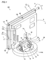
- FIG. 1 A structure of a torque limiter and a base provided with the torque limiter according to the embodiment of the present invention will be now described with reference to Figs. 1 to 13.
- This embodiment of the present invention is applied to a base of a liquid crystal display, which is an exemplary of a display.
- a liquid crystal display 100 comprises a display body 10 and a base 30 capable of turning the display body 10 in a horizontal direction (along arrows A and B) by a prescribed angle ( ⁇ 30 degrees, for example) and inclining in a vertical direction (along arrows C and D) by a prescribed angle, as shown in Fig. 1.
- the display body 10 is an example of the "display screen portion" in the present invention.
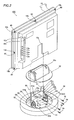
- the base 30 is constituted by a display screen support mechanism 50 supporting a display body 10, a turning portion 31 for turning the display body 10 supported with the display screen support mechanism 50 in the horizontal direction (along arrows A and B in Fig. 1), and a cover member 32 made of resin, as shown in Fig. 2.
- the turning portion 31 is rotatably arranged inside the base 30.
- the inside of the base 30 is constituted by a transmission gear portion 33 for rotating the turning portion 31 and a stepping motor 34 employed as a driving source of the transmission gear portion 33.
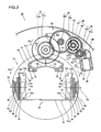
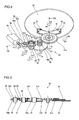
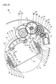
- the transmission gear portion 33 is constituted such that a gear 35 made of resin, a torque limiter 60, a gear 36 made of resin and a gear 37 made of resin are arranged in a gear box 38 made of resin.
- the torque limiter 60 is constituted such that the driving force of the stepping motor 34 is transmitted to the turning portion 31 through the transmission gear portion 33 to turn the turning portion 31 inside the base 30 when the driving force of the stepping motor 34 is less than prescribed driving torque, while the driving force of the stepping motor 34 is not transmitted to the turning portion 31 when the driving force of the stepping motor 34 is prescribed driving torque or more.
- the stepping motor 34 is an example of the "driving source" in the present invention.
- the torque limiter 60 is constituted by a driven gear 61 made of resin, a drive gear 62 made of resin and a spring member 63 (coil spring) made of metal, as shown in Figs. 6 and 7.
- the driven gear 61 and the drive gear 62 are examples of the "first rotating member” and the "second rotating member” in the present invention respectively.
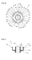
- a plurality of support sections 61b (eight in this embodiment) concentric with a gear portion 61a and extending parallel to an axial direction of rotational axis (one-dot chain line 600) are integrally provided with the driven gear 61, as shown in Fig. 7.
- the eight support sections 61b are provided at equal angular intervals of 45 degrees.
- stop portions 61e horizontally extending from forward ends of the support sections 61b of the driven gear 61 toward the outer peripheral surfaces 61c of the support sections 61b are integrally formed with the support sections 61b as shown in Figs. 10 and 11.
- These stop portions 61e each have a function of inhibiting the drive gear 62 from slipping out from the driven gear 61 along arrow P (upward) by bringing a first side surface 62c of the drive gear 62 into contact with the stop portions 61e when fitting the drive gear 62 around the driven gear 61 as shown in Fig. 8.
- a plurality of (four in this embodiment) stop sections 61f each extending slightly obliquely upward and outward from the axial direction of the rotational axis (one-dot chain line 600 in Fig. 12) between the support section 61b (see Fig. 10) and the support section 61b adjacent thereto (see Fig. 10) of the driven gear 61 are integrally provided with the driven gear 61.
- the four stop sections 61f are concentrically provided at equal angular intervals of 90 degrees.
- stop sections 61f each have a function of inhibiting the drive gear 62 from slipping off from the driven gear 61 along arrow Q (downward) by bringing a second side surface 62d of the drive gear 62 into the stop sections 61f when the drive gear 62 is fitted onto the driven gear 61 as shown in Fig. 9.
- the drive gear 62 is constituted such that a position to be rotatably fitted on the outer peripheral surfaces 61c of the support sections 61b of the driven gear 61 is located by the stop portions 61e (see Fig. 8) and the stop sections 61f (see Fig. 9) of the driven gear 61.
- a plurality of (four in this embodiment) seat portions 61g each extending parallel to the axial direction of the rotational axis (one-dot chain line 600 in Fig. 12) between the support section 61b (see Fig. 10) and the support section 61b adjacent thereto (see Fig. 10) of the driven gear 61 are integrally provided with the driven gear 61, as shown in Figs. 10 and 12.
- the four seat portions 61g are concentrically provided at equal angular intervals of 90 degrees.
- These seat portions 61g each have a function of holding the spring member 63 and inhibiting the spring member 63 from moving along arrow Q (downward) by bringing a first side surface 63a of the spring member 63 into contact with the seat portions 61g when the spring member 63 is press-fitted into the driven gear 61 as shown in Fig. 9.
- projecting portions 61h are integrally formed with the support sections 61b so as to protruding toward the inner peripheral surfaces 61d of the forward ends of the support sections 61b of the driven gear 61.
- the projecting portions 61h each have a function of inhibiting the spring member 63 from slipping out from the driven gear 61 along arrow P (upward) by bringing a second side surface 63b of the spring member 63 into contact with the projecting portions 61h when the spring member 63 is press-fitted into the driven gear 61 as shown in Fig. 8.
- the spring member 63 is so formed as to be reliably kept in the state of being press-fitted into the inner peripheral surfaces 61g of the support sections 61b of the driven gear 61 with the seat portions 61g (see Fig. 9) and the projecting portions 61h (see Fig. 8) of the driven gear 61.
- the stop sections 61f and the seat portions 61g of the driven gear 61 are provided such that each stop section 61f and each seat portion 61g are alternately arranged between each support section 61b and the support section 61b adjacent thereto.
- the drive gear 62 made of resin has a hollow shape and is integrally provided with the inner peripheral surface 62a coming into contact with the outer peripheral surfaces 61c of the driven gear 61, a gear portion 62b, the first side surface 62c and the second side surface 62d.
- the drive gear 62 of the torque limiter 60 is pressed against the driven gear 61 with urging force previously set by the spring member 63 as shown in Fig. 8, and therefore the inner peripheral surface 62a of the drive gear 62 and the outer peripheral surfaces 61c of the driven gear 61 slip so that all driving torque of the drive gear 62 is not transmitted to the driven gear 61, when driving torque, which is not less than the frictional force between the inner peripheral surface 62a of the drive gear 62 and the outer peripheral surfaces 61c of the driven gear 61 following the pressure contact force of the spring member 63, occurs with respect to the drive gear 62.
- a worm gear 39 made of resin is press-fitted into the rotational axis of the stepping motor 34.
- the gear 35 integrally includes a major-diametral gear portion 35a and a minor-diametral gear portion 35b.
- the gear 36 integrally includes a major-diametral gear portion 36a and a minor-diametral gear portion 36b.
- the gear 37 integrally includes a major-diametral gear portion 37a and a minor-diametral gear portion 37b.
- the turning portion 31 of the base 30 is constituted by a circular turning plate 40 made of sheet metal and a turning gear member 41 made of resin.
- the turning gear member 41 is fixed on an upper surface of the turning plate 40 through screws 70.
- the gear box 38 (see Fig. 3) for arranging the transmission gear portion 33 and the stepping motor 34 therein is not shown in the drawing in order to describe a structure of the transmission gear portion 33.
- the worm gear 39 is meshed with the major-diametral gear portion 35a of the gear 35 perpendicular to the rotational axis and the minor-diametral gear portion 35b of the gear 35 is meshed with the gear portion 62b of the drive gear 62 of the torque limiter 60 parallel to the rotational axis.
- the minor-diametral gear portion 35b of the gear 35 is meshed with the gear portion 62b of the drive gear 62 of the torque limiter 60 parallel to the rotational axis.
- the gear portion 61a of the driven gear 61 of the torque limiter 60 is meshed with the major-diametral gear portion 36a of the gear 36 parallel to the rotational axis and the minor-diametral gear portion 36b of the gear 36 is meshed with the major-diametral gear portion 37a of the gear 37 parallel to the rotational axis.
- the minor-diametral gear portion 37b of the gear 37 is meshed with the turning gear portion 41a of the turning gear member 41 parallel to the rotational axis.
- the driving force of the stepping motor 34 is transmitted to the turning plate 40 through the worm gear 39, the gear 35, the torque limiter 60, the gear 36, the gear 37 and the turning gear member 41 from arrangement of the aforementioned gear member shown in Figs. 4 and 5.
- the display screen support mechanism 50 is fixed to the upper surface of the turning plate 40 of the turning portion 31 provided in the base 30 through the four screws 70 as shown in Fig. 2, for rendering the display body 10 rotatable in the vertical direction (along arrows C and D) with respect to the base 30 while supporting the display body 10 in a state inclined in the vertical direction (along arrows C and D) by a prescribed angle with respect to the base 30, as shown in Fig. 1.
- the display screen support mechanism 50 is constituted by a display screen support member 51 made of sheet metal, a pair of vertical support members 52, plate like support shafts 53 of sheet metal, stop members 54 of sheet metal, disc springs 55 of metal (four disc springs in this embodiment), pressure-contact plates 56 and 57 of sheet metal and plate members 58 coming into contact with the disk springs 55 of metal, and the display screen support member 51 is mounted on the pair of vertical support members 52 so as to be rotatable at prescribed torque or more.
- the display screen support member 51 made of sheet metal integrally includes a display body mounting portion 51a and a pair of rotating portions 51b as shown in Fig. 2.
- the display body mounting portion 51a of the display screen support member 51 is provided with four screw receiving holes 51c.
- the pair of rotating portions 51b of the display screen support member 51 are so provided as to extend from both side ends of the display body mounting portion 51a in a vertical direction with respect to a surface of the display body mounting portion 51a respectively.
- the pair of vertical support members 52 include rotating member mounting portions 52a and rotating portion mounting portion 52b respectively, as shown in Figs. 2 and 3.
- the rotating member mounting portions 52a of the vertical support members 52 are provided with four screw receiving holes 52c (see Fig. 3).
- the rotating portion mounting portion 52b of the vertical support members 52 are so provided as to upwardly extend in a vertical direction with respect to surfaces of the rotating member mounting portions 52a from first ends of the rotating member mounting portions 52a.
- the display body 10 is constituted by a front cabinet 11 made of resin and a rear cabinet 12 made of resin.
- a liquid crystal module (not shown) mounted with a liquid crystal panel (not shown) is so formed inside the display body 10 as to be surrounded by the front cabinet 11 and the rear cabinet 12.
- the display body 10 is mounted on the display screen support member 51 by fastening the screws 70 to screw mounting holes (not shown) through the screw receiving holes 51a of the display screen support member 51.
- the rear cabinet 12 is integrally provided with a notch 12a for arranging the display screen support member 51 in a concealed manner.
- a plurality of screw receiving holes 12b are provide on outer peripheral portion of the rear cabinet 12 so that the rear cabinet 12 is mounted on the front cabinet 11 through screws 80.
- a rectangular recess portion 12d is formed in the side surface portion 12c of the rear cabinet 12 and is formed with a plurality of through-holes 12e.
- the plurality of through-holes 12e is provided for connecting cables from AV terminals (not shown) connected to control boards (not shown) for controlling the liquid crystal module to an external apparatus of the display body 10.
- a cover member 32 made of resin is mounted on an upper portion of the base 30, as shown in Fig. 2.
- the cover member 32 made of resin is provided with a notch 32a for rotatably arranging the display screen support mechanism 50.
- a user presses an auto-turn button (not shown) of an attached remote control (not shown) in a state where the display screen support member 51 is directed forward (state where a central portion of the turning gear portion 41a of the turning gear member 41 is meshed with the minor-diametral gear portion 37b of the gear 37), whereby a signal turning the display body 10 (see Fig. 1) in a horizontal direction (along arrow A in Fig. 1) is transmitted to a control circuit portion (not shown) of the display body 10.
- the stepping motor 34 of the base 30 is driven in the basis of this signal. More specifically, the worm gear 39 mounted on the stepping motor 34 rotates along arrow E1 (see Fig.
- the turning portion 31 placed with the display body 10 continuously turns along arrow A (see Fig. 1) at a prescribed rotational speed.
- the drive gear 62 is pressed against the driven gear 61 with the urging force previously set by the spring member 63, and therefore the inner peripheral surface 62a of the drive gear 62 and the outer peripheral surfaces 61c of the driven gear 61 slip so that the driving torque of the drive gear 62 is not transmitted to the driven gear 61, when driving torque, which is not less than the frictional force between the inner peripheral surface 62a of the drive gear 62 and the outer peripheral surfaces 61c of the driven gear 61 following the pressure contact force of the spring member 63, occurs with respect to the drive gear 62.
- the driven gear 61 stops rotation regardless of the rotation of the drive gear 62.
- the driving torque is not transmitted to the driven gear 61, the gear 36, the gear 37 and the turning gear member 41 following the drive gear 62 of the torque limiter 60.
- the torque limiter 60 turns the turning portion 31 along arrow H1 by rotational operation (torque control) similar to the aforementioned rotational operation and the display body 10 (see Fig. 1) is turned along arrow B (see Fig. 1) also at the time of a turning operation along arrow H1 opposite to arrow G1.
- the transmission gear portion 33 includes the torque limiter 60 constituted by three members of the driven gear 61 integrally provided with the eight support sections 61b formed concentrically with the rotational axis at equal angular intervals of 45 degrees, the drive gear 62 fitted onto the outer peripheral surfaces 61c of the support sections 61b of the driven gear 61, and the spring member 63 press-fitted into the inner peripheral surfaces 61d of the support sections 61b of the driven gear 61 and pressing the support sections 61b against the drive gear 62, whereby the driving torque responsive to the pressure contact force by the spring member 63 can be transmitted from the drive gear 62 to the driven gear 61 while bringing the outer peripheral surfaces 61c of the support sections 61b of the driven gear 61 and the inner peripheral surface 62a of the drive gear 62 into direct surface contact with each other.
- the number of components can be inhibited from increase dissimilarly to a structure including a transmission gear portion having a torque limiter interposing a plurality of friction discs or a plurality of steel balls in addition to gear members such as a drive gear and a driven gear.
- the spring member 63 is an annular coil spring and is so formed as to press-fitted into the inner peripheral surfaces 61d of the support sections 61b of the driven gear 61 in a state where the diameter of the coil is contracted from an unloaded state, whereby pressing force for expanding the support sections 61b of the driven gear 61 outward can be easily obtained through restoring force (elastic energy) restoring the shape of the spring from a state where the coil spring (spring member 63) is press-fitted into the inner peripheral surfaces 61d of the support sections 61b of the driven gear 61 into the unloaded state.
- the forward ends of the support sections 61b of the driven gear 61 integrally include the stop portions 61e for inhibiting the drive gear 62 from slipping out along arrow P (see Fig. 7), whereby the stop portions 61e of the driven gear 61 come into contact with the first side surface 62c of the drive gear 62 and hence the drive gear 62 can be easily inhibited from slipping off from the driven gear 61 along arrow P (see Fig. 8) also when the drive gear 62 rotates at prescribed driving torque or more and slips on the outer peripheral surfaces 61c of the support sections 61b of the driven gear 61.
- the driven gear 61 integrally include the stop sections 61f for inhibiting the drive gear 62 from slipping off along arrow Q (see Fig. 7), between the plurality of support sections 61b of the driven gear 61, whereby the stop sections 61f of the driven gear 61 come into contact with the second side surface 62d of the drive gear 62 and hence the drive gear 62 can be easily inhibited from slipping off from the driven gear 61 along arrow Q (see Fig. 9) also when the drive gear 62 rotates at prescribed driving torque or more and slips on the outer peripheral surfaces 61c of the support sections 61b of the driven gear 61.
- the stop portions 61e and the stop sections 61f are so arranged as to hold the drive gear 62 therebetween from above and below along the rotational axial direction (one-dot chain line 600 in Fig. 12) of the drive gear 62, whereby the drive gear 62 can be reliably rotatably held on the outer peripheral surfaces 61c of the support sections 61b of the driven gear 61 with the plurality of stop portions 61e and stop sections 61f.
- the driven gear 61 integrally includes the seat portions 61g for holding the spring member 63, between the plurality of support sections 61b of the driven gear 61, whereby the seat portions 61g inhibit the spring member 63 from moving along arrow Q (see Fig. 9) and hence the spring member 63 can be reliably arranged on the inner peripheral surfaces 61d of the support sections 61b of the driven gear 61.
- the driven gear 61 integrally includes the projecting portions 61h for inhibiting the spring member 63 from slipping off along arrow P (see Fig. 7), on the forward ends of the inner peripheral surfaces 61d of the support sections 61b of the driven gear 61, whereby the projecting portions 61h of the driven gear 61 inhibit the spring member 63 from moving along arrow P (see Fig. 8) and hence the spring member 63 can be easily inhibited from slipping off from the inner peripheral surfaces 61d of the support sections 61b of the driven gear 61 along arrow P (see Fig. 8).
- the projecting portions 61h and the seat portions 61g are so arranged as to hold the spring member 63 therebetween from above and below, whereby the spring member 63 can be reliably held on the inner peripheral surfaces 61d of the support sections 61b of the driven gear 61 with the plurality of projecting portions 61h and seat portions 61g.
- the eight support sections 61b of the driven gear 61 are concentrically arranged at equal angular intervals of 45 degrees and each stop section 61f and each seat portion 61g (four each) are alternately provided between the support sections 61b, whereby the driven gear 61 is integrally provided with the support sections 61b, the stop sections 61f and the seat portions 61g concentrically having different functions respectively and hence the driven gear 61 can stably arrange the drive gear 62 and the spring member 63.
- the present invention is not restricted to this but is also applicable to a display base having a display screen (display panel) other than the liquid crystal panel such as an organic EL panel.
- the present invention is not restricted to this but the support sections 61b of the driven gear 61 may not be alternatively at equal angular intervals of 45 degrees, or the number of the support sections 61b may be alternatively other than eight.
- the present invention is not restricted to this but the stop sections 61f, the seat portions 61g and the projecting portions 61h may not be alternatively provided at equal angular intervals respectively, or the respective numbers of the stop sections 61f, the seat portions 61g and the projecting portions 61h may be alternatively other than four.
- the present invention is not restricted to this but the transmission gear portion may be alternatively constituted by gear members made of metal other than the gear members made of resin, for example.
Landscapes
- Engineering & Computer Science (AREA)
- General Engineering & Computer Science (AREA)
- Mechanical Engineering (AREA)
- Transmission Devices (AREA)
- One-Way And Automatic Clutches, And Combinations Of Different Clutches (AREA)
- Gear Transmission (AREA)
Priority Applications (1)
| Application Number | Priority Date | Filing Date | Title |
|---|---|---|---|
| PL07253980T PL1912014T3 (pl) | 2006-10-10 | 2007-10-09 | Ogranicznik momentu obrotowego i zawierająca go podstawa wyświetlacza |
Applications Claiming Priority (1)
| Application Number | Priority Date | Filing Date | Title |
|---|---|---|---|
| JP2006276028A JP4876833B2 (ja) | 2006-10-10 | 2006-10-10 | トルクリミッタ装置を含む表示装置の台座およびトルクリミッタ装置 |
Publications (3)
| Publication Number | Publication Date |
|---|---|
| EP1912014A2 true EP1912014A2 (fr) | 2008-04-16 |
| EP1912014A3 EP1912014A3 (fr) | 2010-06-16 |
| EP1912014B1 EP1912014B1 (fr) | 2011-06-22 |
Family
ID=38922781
Family Applications (1)
| Application Number | Title | Priority Date | Filing Date |
|---|---|---|---|
| EP07253980A Not-in-force EP1912014B1 (fr) | 2006-10-10 | 2007-10-09 | Limiteur de couple et base de dispositif de visualisation l'incluant |
Country Status (4)
| Country | Link |
|---|---|
| US (1) | US7950610B2 (fr) |
| EP (1) | EP1912014B1 (fr) |
| JP (1) | JP4876833B2 (fr) |
| PL (1) | PL1912014T3 (fr) |
Cited By (4)
| Publication number | Priority date | Publication date | Assignee | Title |
|---|---|---|---|---|
| US20090268107A1 (en) * | 2008-04-23 | 2009-10-29 | Funai Electric Co., Ltd. | Torque Limiter, Display Screen Turning Apparatus Comprising Torque Limiter and Television Set Including Torque Limiter |
| CN101943311A (zh) * | 2010-08-23 | 2011-01-12 | 广东爵仕泳池水疗设备有限公司 | 一种多功能电视支架 |
| GB2475941A (en) * | 2009-09-21 | 2011-06-08 | Paul Turton | Motor driven display mount having a safety cut-off |
| US20220049812A1 (en) * | 2020-08-12 | 2022-02-17 | Syncmold Enterprise Corp. | Supporting device |
Families Citing this family (17)
| Publication number | Priority date | Publication date | Assignee | Title |
|---|---|---|---|---|
| JP4222410B2 (ja) * | 2006-11-07 | 2009-02-12 | 船井電機株式会社 | 表示画面旋回装置 |
| JP4222409B2 (ja) * | 2006-11-07 | 2009-02-12 | 船井電機株式会社 | 表示画面旋回装置 |
| MX2010005605A (es) * | 2007-11-29 | 2010-08-31 | Jslcd Co Ltd | Sistema de visualizacion equipado con funcion sin torsion y funcion de retorno para estado desdoblado. |
| JP5213502B2 (ja) * | 2008-04-17 | 2013-06-19 | 三菱電機株式会社 | 表示装置用回動台 |
| JP4530075B2 (ja) * | 2008-05-07 | 2010-08-25 | 船井電機株式会社 | 表示画面旋回装置およびテレビジョン装置 |
| JP2010091903A (ja) * | 2008-10-10 | 2010-04-22 | Funai Electric Co Ltd | 表示画面旋回装置 |
| JP4956662B2 (ja) * | 2010-10-29 | 2012-06-20 | 株式会社東芝 | 表示装置および電子機器 |
| CN102462259A (zh) * | 2010-11-17 | 2012-05-23 | 苏州工业园区东华工贸有限公司 | 展示架滚筒 |
| JP5750296B2 (ja) * | 2011-04-15 | 2015-07-15 | アルパイン株式会社 | 車載用ディスプレイ装置 |
| US9205784B2 (en) * | 2013-03-15 | 2015-12-08 | Winnebago Industries, Inc. | Dash dock and cradle design |
| KR20160121652A (ko) * | 2015-04-09 | 2016-10-20 | 삼성디스플레이 주식회사 | 디스플레이 장치 |
| JP2019113387A (ja) * | 2017-12-22 | 2019-07-11 | 株式会社東海理化電機製作所 | 回転検出装置 |
| CN112344158B (zh) * | 2019-08-07 | 2022-01-18 | Tcl科技集团股份有限公司 | 一种旋转组件及显示装置 |
| TW202124871A (zh) * | 2019-12-17 | 2021-07-01 | 香港商冠捷投資有限公司 | 顯示裝置 |
| CN111493807A (zh) * | 2020-04-30 | 2020-08-07 | 中国人民解放军西部战区总医院 | 一种组合式消化内科用腹腔镜 |
| CN116928499B (zh) * | 2022-03-29 | 2026-04-17 | 富泰京精密电子(烟台)有限公司 | 旋转支架及包含其的显示器 |
| WO2024048861A1 (fr) * | 2022-09-02 | 2024-03-07 | 엘지전자 주식회사 | Dispositif d'affichage |
Citations (3)
| Publication number | Priority date | Publication date | Assignee | Title |
|---|---|---|---|---|
| JPH0611016A (ja) | 1992-06-22 | 1994-01-21 | Canon Inc | 歯車及び歯車駆動装置及び画像形成装置 |
| JPH07190083A (ja) | 1993-12-28 | 1995-07-28 | Seiko Instr Inc | トルクリミッタ |
| JP2004360809A (ja) | 2003-06-05 | 2004-12-24 | Alpine Electronics Inc | トルクリミッタ付きギアおよび電子機器の動力伝達機構 |
Family Cites Families (20)
| Publication number | Priority date | Publication date | Assignee | Title |
|---|---|---|---|---|
| KR880002215Y1 (ko) * | 1986-08-05 | 1988-06-22 | 송병희 | 개량 방 비 |
| JPH07203335A (ja) * | 1993-12-28 | 1995-08-04 | Mitsubishi Electric Corp | 回転装置 |
| JP3361230B2 (ja) * | 1996-06-19 | 2003-01-07 | 株式会社三協精機製作所 | フリクション機構付き小型モータ |
| JPH1054449A (ja) * | 1996-08-08 | 1998-02-24 | Higashifuji Seisakusho:Kk | クラッチ付きモータ |
| US6647819B1 (en) * | 2000-10-23 | 2003-11-18 | Punch Video, Inc. | Transmission assembly for a ceiling-mounted TV support |
| US20030050121A1 (en) * | 2001-09-07 | 2003-03-13 | Seiichi Takada | Torque limiter and rotary member with the torque limiter |
| WO2004028151A1 (fr) * | 2002-09-17 | 2004-04-01 | Sharp Kabushiki Kaisha | Dispositif d'affichage mince |
| JP2004316794A (ja) * | 2003-04-17 | 2004-11-11 | Berutekku Kk | 回転台 |
| CN100427820C (zh) * | 2003-08-29 | 2008-10-22 | 株式会社村上开明堂 | 转动支座 |
| US7184266B1 (en) * | 2005-08-05 | 2007-02-27 | Boom Electronics Inc. | Automatic monitor sliding system |
| US7384021B2 (en) * | 2006-03-22 | 2008-06-10 | Chun-Chieh Liao | Rotation mechanism for televisions |
| JP2008040288A (ja) * | 2006-08-09 | 2008-02-21 | Shimonishi Giken Kogyo Kk | 平面ディスプレイの駆動装置 |
| JP4179371B2 (ja) * | 2006-10-27 | 2008-11-12 | 船井電機株式会社 | 表示画面旋回装置 |
| JP4222409B2 (ja) * | 2006-11-07 | 2009-02-12 | 船井電機株式会社 | 表示画面旋回装置 |
| JP4222410B2 (ja) * | 2006-11-07 | 2009-02-12 | 船井電機株式会社 | 表示画面旋回装置 |
| JP3128970U (ja) * | 2006-11-14 | 2007-02-01 | 船井電機株式会社 | 表示画面旋回装置 |
| JP3132678U (ja) * | 2006-12-18 | 2007-06-21 | 下西技研工業株式会社 | モニタ用スイーベル装置 |
| JP4254870B2 (ja) * | 2007-02-08 | 2009-04-15 | 船井電機株式会社 | 表示画面旋回装置 |
| JP2009264436A (ja) * | 2008-04-23 | 2009-11-12 | Funai Electric Co Ltd | トルクリミッタ装置、トルクリミッタ装置を備えた表示画面旋回装置およびトルクリミッタ装置を含むテレビジョン装置 |
| JP4530075B2 (ja) * | 2008-05-07 | 2010-08-25 | 船井電機株式会社 | 表示画面旋回装置およびテレビジョン装置 |
-
2006
- 2006-10-10 JP JP2006276028A patent/JP4876833B2/ja not_active Expired - Fee Related
-
2007
- 2007-10-09 US US11/869,188 patent/US7950610B2/en not_active Expired - Fee Related
- 2007-10-09 PL PL07253980T patent/PL1912014T3/pl unknown
- 2007-10-09 EP EP07253980A patent/EP1912014B1/fr not_active Not-in-force
Patent Citations (3)
| Publication number | Priority date | Publication date | Assignee | Title |
|---|---|---|---|---|
| JPH0611016A (ja) | 1992-06-22 | 1994-01-21 | Canon Inc | 歯車及び歯車駆動装置及び画像形成装置 |
| JPH07190083A (ja) | 1993-12-28 | 1995-07-28 | Seiko Instr Inc | トルクリミッタ |
| JP2004360809A (ja) | 2003-06-05 | 2004-12-24 | Alpine Electronics Inc | トルクリミッタ付きギアおよび電子機器の動力伝達機構 |
Cited By (8)
| Publication number | Priority date | Publication date | Assignee | Title |
|---|---|---|---|---|
| US20090268107A1 (en) * | 2008-04-23 | 2009-10-29 | Funai Electric Co., Ltd. | Torque Limiter, Display Screen Turning Apparatus Comprising Torque Limiter and Television Set Including Torque Limiter |
| EP2112388A3 (fr) * | 2008-04-23 | 2010-05-26 | Funai Electric Co., Ltd. | Limiteur de couple |
| US8120715B2 (en) | 2008-04-23 | 2012-02-21 | Funai Electric Co., Ltd. | Torque limiter, display screen turning apparatus comprising torque limiter and television set including torque limiter |
| GB2475941A (en) * | 2009-09-21 | 2011-06-08 | Paul Turton | Motor driven display mount having a safety cut-off |
| CN101943311A (zh) * | 2010-08-23 | 2011-01-12 | 广东爵仕泳池水疗设备有限公司 | 一种多功能电视支架 |
| CN101943311B (zh) * | 2010-08-23 | 2012-12-26 | 广东爵仕泳池水疗设备有限公司 | 一种多功能电视支架 |
| US20220049812A1 (en) * | 2020-08-12 | 2022-02-17 | Syncmold Enterprise Corp. | Supporting device |
| US11781706B2 (en) * | 2020-08-12 | 2023-10-10 | Syncmold Enterprise Corp. | Supporting device |
Also Published As
| Publication number | Publication date |
|---|---|
| JP4876833B2 (ja) | 2012-02-15 |
| EP1912014A3 (fr) | 2010-06-16 |
| US7950610B2 (en) | 2011-05-31 |
| US20080083293A1 (en) | 2008-04-10 |
| JP2008095760A (ja) | 2008-04-24 |
| EP1912014B1 (fr) | 2011-06-22 |
| PL1912014T3 (pl) | 2011-11-30 |
Similar Documents
| Publication | Publication Date | Title |
|---|---|---|
| EP1912014B1 (fr) | Limiteur de couple et base de dispositif de visualisation l'incluant | |
| EP1921367B1 (fr) | Appareil de rotation d'écran de visualisation | |
| US8094244B2 (en) | Display screen turning apparatus | |
| US8237874B2 (en) | Display screen turning apparatus | |
| EP2116754B1 (fr) | Dispositif de rotation d'écran d'affichage | |
| EP1662194B1 (fr) | Support rotatif | |
| EP1921368A2 (fr) | Appareil de rotation d'écran de visualisation | |
| US20080100997A1 (en) | Monitor turnning device | |
| CN113074182B (zh) | 一种转轴及安装有转轴的设备 | |
| US8120715B2 (en) | Torque limiter, display screen turning apparatus comprising torque limiter and television set including torque limiter | |
| US20070222776A1 (en) | Display rotation apparatus | |
| JP7510185B2 (ja) | クラッチ装置およびモータユニット | |
| CN101031045B (zh) | 平板显示器 | |
| JP2009015139A (ja) | 表示画面旋回装置 | |
| US20150198975A1 (en) | Cover with Angle Adjustable Standing Slot | |
| JP4645588B2 (ja) | トルクリミッタ装置を含む表示装置の台座およびトルクリミッタ装置 | |
| JP2007303496A (ja) | 重量物支持台 | |
| CN220523054U (zh) | 一种转轴机构及投影设备 | |
| JP6918426B2 (ja) | トルク伝達装置 | |
| JPH0428141Y2 (fr) | ||
| JP3421929B2 (ja) | フリクショントルク伝達機構 | |
| JP3281114B2 (ja) | トルクリミッタ | |
| JP2020067573A (ja) | 画像表示装置及び回動装置 | |
| US6556789B2 (en) | Diaphragm switching apparatus | |
| CN119532308A (zh) | 一种可旋转装置及关节模块 |
Legal Events
| Date | Code | Title | Description |
|---|---|---|---|
| PUAI | Public reference made under article 153(3) epc to a published international application that has entered the european phase |
Free format text: ORIGINAL CODE: 0009012 |
|
| AK | Designated contracting states |
Kind code of ref document: A2 Designated state(s): AT BE BG CH CY CZ DE DK EE ES FI FR GB GR HU IE IS IT LI LT LU LV MC MT NL PL PT RO SE SI SK TR |
|
| AX | Request for extension of the european patent |
Extension state: AL BA HR MK RS |
|
| PUAL | Search report despatched |
Free format text: ORIGINAL CODE: 0009013 |
|
| AK | Designated contracting states |
Kind code of ref document: A3 Designated state(s): AT BE BG CH CY CZ DE DK EE ES FI FR GB GR HU IE IS IT LI LT LU LV MC MT NL PL PT RO SE SI SK TR |
|
| AX | Request for extension of the european patent |
Extension state: AL BA HR MK RS |
|
| RIC1 | Information provided on ipc code assigned before grant |
Ipc: F16M 11/08 20060101AFI20080118BHEP Ipc: F16D 43/21 20060101ALI20100512BHEP Ipc: F16D 7/02 20060101ALN20100512BHEP |
|
| GRAP | Despatch of communication of intention to grant a patent |
Free format text: ORIGINAL CODE: EPIDOSNIGR1 |
|
| 17P | Request for examination filed |
Effective date: 20101119 |
|
| RIC1 | Information provided on ipc code assigned before grant |
Ipc: F16D 43/21 20060101ALI20101207BHEP Ipc: F16D 7/02 20060101ALN20101207BHEP Ipc: F16M 11/08 20060101AFI20101207BHEP |
|
| RTI1 | Title (correction) |
Free format text: TORQUE LIMITER AND DISPLAY BASE INCLUDING THE SAME |
|
| AKX | Designation fees paid |
Designated state(s): DE FR GB PL |
|
| GRAS | Grant fee paid |
Free format text: ORIGINAL CODE: EPIDOSNIGR3 |
|
| GRAA | (expected) grant |
Free format text: ORIGINAL CODE: 0009210 |
|
| AK | Designated contracting states |
Kind code of ref document: B1 Designated state(s): DE FR GB PL |
|
| REG | Reference to a national code |
Ref country code: GB Ref legal event code: FG4D |
|
| REG | Reference to a national code |
Ref country code: DE Ref legal event code: R096 Ref document number: 602007015356 Country of ref document: DE Effective date: 20110811 |
|
| REG | Reference to a national code |
Ref country code: PL Ref legal event code: T3 |
|
| PLBE | No opposition filed within time limit |
Free format text: ORIGINAL CODE: 0009261 |
|
| STAA | Information on the status of an ep patent application or granted ep patent |
Free format text: STATUS: NO OPPOSITION FILED WITHIN TIME LIMIT |
|
| 26N | No opposition filed |
Effective date: 20120323 |
|
| REG | Reference to a national code |
Ref country code: DE Ref legal event code: R097 Ref document number: 602007015356 Country of ref document: DE Effective date: 20120323 |
|
| PGFP | Annual fee paid to national office [announced via postgrant information from national office to epo] |
Ref country code: PL Payment date: 20130918 Year of fee payment: 7 |
|
| PGFP | Annual fee paid to national office [announced via postgrant information from national office to epo] |
Ref country code: DE Payment date: 20131002 Year of fee payment: 7 Ref country code: FR Payment date: 20131009 Year of fee payment: 7 Ref country code: GB Payment date: 20131009 Year of fee payment: 7 |
|
| REG | Reference to a national code |
Ref country code: DE Ref legal event code: R119 Ref document number: 602007015356 Country of ref document: DE |
|
| GBPC | Gb: european patent ceased through non-payment of renewal fee |
Effective date: 20141009 |
|
| PG25 | Lapsed in a contracting state [announced via postgrant information from national office to epo] |
Ref country code: GB Free format text: LAPSE BECAUSE OF NON-PAYMENT OF DUE FEES Effective date: 20141009 Ref country code: DE Free format text: LAPSE BECAUSE OF NON-PAYMENT OF DUE FEES Effective date: 20150501 |
|
| REG | Reference to a national code |
Ref country code: FR Ref legal event code: ST Effective date: 20150630 |
|
| PG25 | Lapsed in a contracting state [announced via postgrant information from national office to epo] |
Ref country code: FR Free format text: LAPSE BECAUSE OF NON-PAYMENT OF DUE FEES Effective date: 20141031 |
|
| PG25 | Lapsed in a contracting state [announced via postgrant information from national office to epo] |
Ref country code: PL Free format text: LAPSE BECAUSE OF NON-PAYMENT OF DUE FEES Effective date: 20141009 |