EP1912035B1 - Refroidisseur de véhicule automobile - Google Patents
Refroidisseur de véhicule automobile Download PDFInfo
- Publication number
- EP1912035B1 EP1912035B1 EP07024461A EP07024461A EP1912035B1 EP 1912035 B1 EP1912035 B1 EP 1912035B1 EP 07024461 A EP07024461 A EP 07024461A EP 07024461 A EP07024461 A EP 07024461A EP 1912035 B1 EP1912035 B1 EP 1912035B1
- Authority
- EP
- European Patent Office
- Prior art keywords
- edge
- tube
- recess
- motor vehicle
- openings
- Prior art date
- Legal status (The legal status is an assumption and is not a legal conclusion. Google has not performed a legal analysis and makes no representation as to the accuracy of the status listed.)
- Expired - Lifetime
Links
- 239000011324 bead Substances 0.000 claims description 40
- 238000001816 cooling Methods 0.000 claims description 17
- 239000006228 supernatant Substances 0.000 description 9
- 230000002093 peripheral effect Effects 0.000 description 5
- 239000000243 solution Substances 0.000 description 5
- 230000000694 effects Effects 0.000 description 4
- 238000009434 installation Methods 0.000 description 4
- 238000005192 partition Methods 0.000 description 3
- 230000015572 biosynthetic process Effects 0.000 description 2
- 238000005755 formation reaction Methods 0.000 description 2
- 238000001746 injection moulding Methods 0.000 description 2
- 238000000034 method Methods 0.000 description 2
- 238000004080 punching Methods 0.000 description 2
- 238000007789 sealing Methods 0.000 description 2
- 238000005476 soldering Methods 0.000 description 2
- 229910052782 aluminium Inorganic materials 0.000 description 1
- XAGFODPZIPBFFR-UHFFFAOYSA-N aluminium Chemical compound [Al] XAGFODPZIPBFFR-UHFFFAOYSA-N 0.000 description 1
- 238000005452 bending Methods 0.000 description 1
- 239000002826 coolant Substances 0.000 description 1
- 239000000498 cooling water Substances 0.000 description 1
- 230000001419 dependent effect Effects 0.000 description 1
- 238000005516 engineering process Methods 0.000 description 1
- 238000001125 extrusion Methods 0.000 description 1
- 238000007373 indentation Methods 0.000 description 1
- 238000003780 insertion Methods 0.000 description 1
- 230000037431 insertion Effects 0.000 description 1
- 239000007788 liquid Substances 0.000 description 1
- 238000004519 manufacturing process Methods 0.000 description 1
- 229910052751 metal Inorganic materials 0.000 description 1
- 239000002184 metal Substances 0.000 description 1
- 238000002360 preparation method Methods 0.000 description 1
- 238000003825 pressing Methods 0.000 description 1
- 230000000284 resting effect Effects 0.000 description 1
- 239000007787 solid Substances 0.000 description 1
- 230000009466 transformation Effects 0.000 description 1
Images






Classifications
-
- F—MECHANICAL ENGINEERING; LIGHTING; HEATING; WEAPONS; BLASTING
- F28—HEAT EXCHANGE IN GENERAL
- F28F—DETAILS OF HEAT-EXCHANGE AND HEAT-TRANSFER APPARATUS, OF GENERAL APPLICATION
- F28F9/00—Casings; Header boxes; Auxiliary supports for elements; Auxiliary members within casings
- F28F9/02—Header boxes; End plates
- F28F9/0219—Arrangements for sealing end plates into casing or header box; Header box sub-elements
- F28F9/0224—Header boxes formed by sealing end plates into covers
- F28F9/0226—Header boxes formed by sealing end plates into covers with resilient gaskets
-
- F—MECHANICAL ENGINEERING; LIGHTING; HEATING; WEAPONS; BLASTING
- F28—HEAT EXCHANGE IN GENERAL
- F28F—DETAILS OF HEAT-EXCHANGE AND HEAT-TRANSFER APPARATUS, OF GENERAL APPLICATION
- F28F9/00—Casings; Header boxes; Auxiliary supports for elements; Auxiliary members within casings
- F28F9/02—Header boxes; End plates
- F28F9/04—Arrangements for sealing elements into header boxes or end plates
- F28F9/16—Arrangements for sealing elements into header boxes or end plates by permanent joints, e.g. by rolling
- F28F9/18—Arrangements for sealing elements into header boxes or end plates by permanent joints, e.g. by rolling by welding
- F28F9/182—Arrangements for sealing elements into header boxes or end plates by permanent joints, e.g. by rolling by welding the heat-exchange conduits having ends with a particular shape, e.g. deformed; the heat-exchange conduits or end plates having supplementary joining means, e.g. abutments
-
- F—MECHANICAL ENGINEERING; LIGHTING; HEATING; WEAPONS; BLASTING
- F28—HEAT EXCHANGE IN GENERAL
- F28D—HEAT-EXCHANGE APPARATUS, NOT PROVIDED FOR IN ANOTHER SUBCLASS, IN WHICH THE HEAT-EXCHANGE MEDIA DO NOT COME INTO DIRECT CONTACT
- F28D21/00—Heat-exchange apparatus not covered by any of the groups F28D1/00 - F28D20/00
- F28D2021/0019—Other heat exchangers for particular applications; Heat exchange systems not otherwise provided for
- F28D2021/008—Other heat exchangers for particular applications; Heat exchange systems not otherwise provided for for vehicles
- F28D2021/0091—Radiators
- F28D2021/0094—Radiators for recooling the engine coolant
-
- F—MECHANICAL ENGINEERING; LIGHTING; HEATING; WEAPONS; BLASTING
- F28—HEAT EXCHANGE IN GENERAL
- F28F—DETAILS OF HEAT-EXCHANGE AND HEAT-TRANSFER APPARATUS, OF GENERAL APPLICATION
- F28F9/00—Casings; Header boxes; Auxiliary supports for elements; Auxiliary members within casings
- F28F9/02—Header boxes; End plates
- F28F2009/0285—Other particular headers or end plates
- F28F2009/029—Other particular headers or end plates with increasing or decreasing cross-section, e.g. having conical shape
Definitions
- the invention relates to a motor vehicle radiator, consisting of flat tubes, corrugated fins and tubesheets with an erected peripheral edge, and with openings corresponding to the cross section of the flat tubes, in which open the ends of the flat tubes, wherein the openings are formed with collars, and with collecting boxes made of plastic, which are mechanically fastened at its edge bead to the edge of the substantially flat tubesheets with the addition of a seal, wherein the edge of the tubesheets is bent onto the edge bead of the collecting boxes in the manner of a clamping.
- a motor vehicle radiator is out of the Fig. 2 of the DE 34 40 489 C2 known.
- the known motor vehicle radiator has only at one end of the flat tubes a substantially flat tube plate with a collecting box.
- the flat tubes are formed there with a longitudinal ridge, so that the cooling water is deflected at the other end of the flat tubes and flows back to the collection box. Since in the document a completely different from the invention described below task has been solved, seems the Fig. 2 only randomly, ie not purposefully, to show the characteristics of the generic term.
- a circumferential groove is formed for clamping the collecting tank on the tube plate in the tube plate, in which the seal is their recording and therefore can not slip, as well as in the Fig. 6 of the mentioned document.
- Such tube sheets are then not considered to be substantially flat.
- the present invention is based on a motor vehicle radiator with a substantially planar tube sheet.
- EP 1 273 864 A2 are also no substantially flat tube sheets available, but there the object was achieved, which also plays a role in the present invention and which is to be able to equip the motor vehicle radiator with the smallest possible amount of change with smaller block depths of the cooling network (flat tubes and corrugated fins).
- the solution takes place there by the provision of a second tube plate or an intermediate bottom. It is for reasons of cost still advantageous collecting boxes made of plastic - not made of metal - to use because additional functional elements can be easily realized by appropriate design of the injection molding tool.
- the WO 00/33009 A1 agrees with the preamble of claim 1, because there are substantially flat tube sheets available. There, a seal was further provided which extends over the entire tube sheet and is therefore also designed to seal the pipe ends in the openings of the tube sheet.
- the lateral projection of the tube sheets on the cooling network is quite large there, which is unfavorable in terms of the required installation space. If a cooling network with a different depth dimension is to be used, which is desired in many cases, then inevitably another, adapted thereto, gasket is needed, whereby the cost is increased. Further, the pipe ends protrude far into the interior of the header, which is also unfavorable in terms of pressure loss.
- the tube ends were soldered in the openings of the tube bottom, so that a planar seal formed as described above is not required.
- the heat exchanger from this publication with respect to pressure loss is also not advantageous.
- two rows of indentations were formed in the tube bottom, ie incorporated into the non-planar tubesheet, which serve as a stop for the wall of the collecting box.
- the seal assembly could be improved here.
- the object of the present invention is to design the motor vehicle radiator so that the seal assembly is simplified, that the supernatant of the Cylinder box is further reduced over the cooling network, but with the option to provide the cooler in case of need in an economical manner with a cooling network of smaller block depth, and that the internal pressure loss is comparatively reduced
- a circumferential projection is provided at the bead of the collecting tanks, which is supported on the flat tube sheets and provides a space for receiving the seal to the edge of the tube sheet down.
- a circumferential projection is provided at the bead of the collecting tanks, which is supported on the flat tube sheets and provides a space for receiving the seal to the edge of the tube sheet down.
- the openings in the tubesheets extend approximately to the projection on the manifolds.
- the edge bead of the manifolds is formed with a recess into which engages the bent edge of the tube sheets.
- Such a trained motor vehicle radiator can be designed with a very small change effort with a cooling network lesser block depth.
- a motor vehicle radiator with a smaller block depth the above-mentioned feature, according to which the openings in the tubesheets extend to the projection on the collecting boxes is not realized.
- the preparation of the required tube plates with smaller openings is also conceivable cost, since this is possible in principle with the existing tube bottom tool, with only the integrated in the tool punching kit for the larger openings must be replaced by a punching kit for smaller openings.
- a motor vehicle radiator in which the openings extend to the projection on the collecting box requires a relatively small installation space, because the projection of the edge bead of the collecting tank on the flat tubes is conceivable low, since no space-filling channel is provided in the tube sheet.
- the channel is not only provided for receiving the seal, but it represents a stop for the edge bead of the header, which therefore can not occur in the Verklamm réellesvorgang and during operation of the motor vehicle radiator to the inside. This function is ensured here by the fact that a recess has been provided at the edge bead of the header, in which engages the edge of the tube sheet.
- the Collecting box does not fall inward, but he remains stable in position, although the tube sheet is substantially flat, ie it has no circumferential groove and no significant other deformations between the openings that protrude above the surface of the tube sheet and a stop for could form the collection box.
- the recess which is preferably arranged in the entire peripheral edge bead of the collecting tank, can be further reinforced by spaced webs. The webs form quasi "fan" in the recess.
- the edge of the tube sheet is, as is known, likewise formed with projections arranged at intervals. The supernatants are designed so that they each fit into a "compartment" in the recess into which they are bendable by more than 90 ° inwards.
- the Verklamm ceremoniesstechnikmaschinemaschine has punches, which act in the nature of hold-down and interposed Umformstempel that perform the transformation of the supernatants.
- the hold-down punches take time shortly before the Umformstempeln and cause the Umformstempel not change the position of the edge during the forming process or during the clamping. After reshaping the supernatants, the position, as already mentioned, secured by the deformed supernatants.
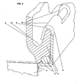
- Fig. 1 to 5 show partial perspective sections of the motor vehicle radiator according to the invention, which may be, for example, a cooled by cooling air coolant radiator or a charge air cooler.
- FIGS. 6-28 show not inventive embodiments.
- the Fig. 24 shows a front view and the Fig. 25 a side view of an essential part of a charge air cooler.
- the motor vehicle radiator according to the invention ( Fig. 1-5 ) is known from a cooling network consisting of a series of flat tubes 1 and corrugated fins 2, and from two tube sheets 3, in whose openings 4 the opposite ends of the flat tubes 1 open, constructed.
- the tube sheets 3 are each connected to a collecting box 6 .
- the Fig. 1 shows a section of a side of the motor vehicle radiator, with a part of a tube sheet 3, with only two flat tubes 1 of the mentioned series, with as many openings 4, and with a piece of corrugated fins 2, which are arranged between the flat tubes 1 and by the cooling air ( dashed arrows) flows through.
- the openings 4 are formed with pointing to the flat tubes 1 and the corrugated fins 2 collar 5 , where the ends of the flat tubes 1 are soldered tight and durable.
- the ends of the flat tubes 1 terminate below the surface of the tube bottom 3 in order to keep the pressure loss of the flowing through the flat tubes 1 , to be cooled medium (solid arrows) low. Furthermore, a part of a collecting box 6 can be seen, which was made of plastic by injection molding.
- the collecting box 6 is mechanically fastened at its peripheral edge bead 7 with the peripheral deformed edge 8 of the substantially flat tube plate 3 with the addition of a seal 9 , wherein the deformed edge 8 of the tube plate 3 is bent on the edge bead 7 of the collecting box 6 in the manner of a clamping ,
- the opposite side of the motor vehicle radiator, not shown, is of identical design.
- a circumferential projection 10 is provided, which is supported on the flat tube sheets 3 and provides a space 11 for receiving the seal 9 to the deformed edge 8 of the tube sheets 3 out.
- the seal 9 has a round cross section projecting beyond the cross section of the space 11 , which is squeezed wide in the course of the clamping, whereby the sealing effect arises, or the space 11 is filled with the seal 9 .
- the openings 4 in the tubesheets 3 extend at both ends approximately to the circumferential projection 10 on the edge bead 7 of the manifolds 6, whereby only a slight projection of the rim 8 over the circumference of the cooling network (flat tubes / corrugated fins) was created.
- the projection 10 resting on the flat tubesheet 3 is arranged approximately perpendicularly above the one end of the openings 4 .
- the other end of the openings 4 or the opposite side of the collecting tank 6 is not shown, but is identical, which is also expressed by the "circumferential" edge 7 of the tube bottom and the "peripheral" edge bead 7 of the collecting box shall be.
- the edge bead 7 of the manifolds 6 is formed with a recess 12 into which the deformed edge 8 of the tube plates 3 engages. While the projection 10 is formed on the underside of the edge bead 7 of the collecting tank 6 , the recess 12 is formed on the upper side of the edge bead 7 of the collecting box 6 in the manner of a circumferential groove.
- the engaging in the recess 12 formed edge 8 of the tube sheet requires a bend of this edge 8 inwardly by much more than 90 °, so that the holding function of the deformed edge 8 relative to the wall of the collecting tank 6 is to be fulfilled.
- the edge 8 was bent inwards by approximately 130 ° from the vertical inwards, into the recess 12 of the edge bead 7 .
- the collecting box 6 has no other stop on the tube sheet 3, since substantially flat tube sheets 3 are provided.
- the reshaped edge 8 has been bent as a whole in the recess 12 into it.
- the Fig. 2 and 3 show a change, which consists in that the deformed edge 8 of the tube sheets 3 is formed with known at intervals spaced projections 20 . These projections 20 have been bent into the recess 12 .
- the recess 12 can be divided by means of webs 14 into compartments 15 .
- the webs 14 lead to a higher rigidity in the recess 12, which can therefore be formed with a smaller wall thickness, whereby the supernatant ü on the cooling network is further reduced.
- a device for clamping the collecting tank 6 to the tube bottom 3 can be seen.
- the device has a series of punches.
- a forming punch 40 alternates with a holding-down punch 30 .
- the hold-down punches 30 each engage in a compartment 15 of the recess 12 and hold the collection box 6 in the desired position.
- a forming die 40 bends a supernatant 20 on the deformed edge 8 in the adjacent compartment 15 into. Only a forming punch 40 and a holding-down punch 30 were shown.
- the hold-down punches 30 have to take effect somewhat earlier than the forming punches 40 in terms of time.
- the device is located in a forming machine, which was simply provided with the reference numeral 50 .
- the punches 30 and 40 act approximately perpendicular to the flat tubesheet 3 on the deformed edge 8 and the edge bead 7 a.
- FIGS. 6 27 which show no embodiments protected by this invention, the components of the motor vehicle radiator already described above were nevertheless assigned reference numerals which are extended by one hundred. Other components, which have not been described above or are not present, have also received one hundred reference numerals.
- the plastic collecting tanks 106 have an air inlet or outlet nozzle 190 . (only one of the two manifolds drawn)
- the edge bead 107 of the manifolds 106 is fixed at the edge 108 of the tube plates 103 by clamping.
- the intercooler has a series of flat tubes 101 with corrugated fins 102 arranged therebetween.
- the tube plates 103 have openings, which are each provided with a collar 105 , which are aligned with the cooling network.
- the cooler also has on each narrow side a side part 180. One of them can be seen in the pictures.
- an insert 160 is used, which is inserted into the tube plate 103 .
- Various embodiments of the insert 160 are in the 10, 11 and 12 shown.
- the insert 160 is made of aluminum sheet by forming.
- the insert 160 has an edge strip 161 of different design according to the various embodiments , which gives the insert 160 a frame-like configuration.
- transverse webs 165 were provided between the two longitudinal sides of the insert 160 and its deformed marginal strip 161 , respectively.
- the transverse webs 165 can improve the stability of the insert 160 and can also impart a gas or liquid flow directing effect by correspondingly forming the angle of attack ⁇ ( Fig. 12 ).
- the size of the Angle of attack ⁇ can change from transverse web 165 to transverse web 165 as a function of the position of the inlet or outlet connection 190 .
- the transverse webs 165 are connected at both ends only via a relatively narrow and therefore rotatable web 166 with the edge strip 161 . Nevertheless, the transverse webs 165 only represent an option that can be dispensed with, especially with smaller radiator sizes.
- protrusions 167 located at the lower edge of the trim strip 161 . These projections 167 fit into openings 168 which are present in the tube plate 103 . Projections 167 and openings 168 together constitute a suitable measure for provisionally fixing the edge strip 161 in the tube sheet 103 so that the soldering process can be carried out. ( Fig. 8 . 11 . 27 ) This caused concerns about tightness are unfounded in view of the level of development of the soldering technology.
- the Fig. 9 the section A - A shows, in the Fig. 8 was drawn.
- the seal 109 is located in a circumferential recess of the edge bead 107 of the collecting tank 106.
- the seal 109 itself is a manufactured by extrusion rubber band approximately rectangular cross-section, which is cut to appropriate length.
- the recess in the edge bead 107 has at intervals arranged cross-sectional constrictions 171, which in the Fig. 9 are recognizable. These serve to give the seal 109 appropriate hold because it is trapped there.
- the sealing effect is achieved by pressing the seal 109 on the edge strip 161 of the insert 160 .
- the edge bead 107 rests against the already described transverse webs 165 of the insert part 160 and thus can not slip.
- the transverse webs 165 was dispensed with the transverse webs 165 and therefore only individual in-line formations were formed in the insert 160 , which serve as a means for supporting the edge bead 107 .
- FIGS. 14, 15 and 16 With regard to the universal and cost-effective use of plastic collecting tanks 106 already mentioned in the introduction, reference is hereby made to the FIGS. 14, 15 and 16 be pointed out.
- a partition wall 188 was formed in the plastic collection box 106 as its component, with which, as is known, the flow through the radiator can be selected as it is advantageous for certain applications. It was further provided there, the seal 109 with a cross-connection 187 form , on which the partition wall 188 comes to rest during assembly of the collecting tank 106 . Below the partition wall 188 or the transverse connection 187 , the complete flow deflection can be achieved by a further insertion part 189 .
- FIGS. 17 to 23 show partial views or sections through the edge 108 of the tube sheet 103 and the edge strip 161 of the insert 160 in various examples according to the prior art from which inter alia, the clamping closer.
- Fig. 17 shows particularly well, has the outer edge of the edge bead 107 cutouts, which are provided where the projections 120 are present at the edge 108 of the tube sheet 103 .
- the Supernatants 120 are, as described above, bent inwards and cause the clamping.
- the Fig. 26 and 27 each show a view of the inside of a substantially flat tube bottom 103, wherein in the Fig. 26 the tube plate 103 of adeckenkeitkühlers and in the Fig. 27 the tube plate 103 of a charge air cooler is shown.
- the openings 104 for the ends of the flat tubes can be seen there as well as the nubs described 176 and those openings 168 which receive the projections 167 at the lower edge of the edge strip 161 .
- the edge 108 of the tube plate 103 is merely bent, ie erect.
- the tube plates 3, 103 have no groove for receiving the seal.
- the Fig. 28 shows a modified embodiment of the second proposed solution, in which the collar 105 are formed at the openings 104 in the tube sheet 103 in the direction of the collecting tank 106 pointing.
- the collar 105 are formed at the openings 104 in the tube sheet 103 in the direction of the collecting tank 106 pointing.
- the insert 160 may be described on FIGS. 19 and 20 to get expelled.
Landscapes
- Engineering & Computer Science (AREA)
- Physics & Mathematics (AREA)
- Thermal Sciences (AREA)
- Mechanical Engineering (AREA)
- General Engineering & Computer Science (AREA)
- Heat-Exchange Devices With Radiators And Conduit Assemblies (AREA)
- Cooling, Air Intake And Gas Exhaust, And Fuel Tank Arrangements In Propulsion Units (AREA)
Claims (4)
- Refroidisseur de véhicule automobile, se composant de tubes plats (1), d'ailettes ondulées (2) et de deux fonds de tube (3) avec un bord continu redressé (8) et avec des ouvertures (4) adaptées à la section transversale des tubes plats (1), dans lesquelles débouchent les extrémités opposées des tubes plats (1), dans lequel les ouvertures (4) sont munies de rebords (5) qui sont orientés en direction du réseau de refroidissement, et avec deux caissons collecteurs (6) en matière plastique qui sont mécaniquement fixés par leur bourrelet périphérique continu (7) au bord redressé (8) des fonds de tubes (3) essentiellement plans avec interposition d'un joint d'étanchéité (9), dans lequel le bourrelet périphérique (7) des caissons collecteurs (6) est réalisé avec un évidement (12), dans lequel le bord redressé (8) des fonds de tubes (3) est recourbé vers l'intérieur à la manière d'un agrafage, dans lequel il est prévu sur le bourrelet périphérique (7) des caissons collecteurs (6) une saillie continue (10), qui s'appuie sur les fonds de tubes (3) et qui crée, en direction du bord redressé (8) des fonds de tubes (3), un espace (11) disponible pour recevoir le joint d'étanchéité (9),
caractérisé en ce qu'il se trouve des ergots (21) disposés à distance sur la saillie continue (10), qui servent pour positionner le joint d'étanchéité (9), et en ce que les extrémités des tubes sont soudées aux rebords (5) et ne pénètrent pas à l'intérieur du caisson collecteur (6). - Refroidisseur dé véhicule automobile selon la revendication 1, caractérisé en ce que l'évidement (12) est réalisé en continu et est renforcé avec des nervures (14) réalisées à certaines distances, de telle manière que l'évidement (12) se présente sous la forme d'une série de cases (15).
- Refroidisseur de véhicule automobile selon la revendication 2, caractérisé en ce que le bord redressé (8) des fonds de tubes (3) est réalisé avec des protubérances (20) disposées à certaines distances, dans lequel ces distances correspondent aux distances des nervures (14) dans l'évidement (12), de telle manière que les protubérances (20) sur le bord redressé du fond de tube s'engagent dans une case (15) sur deux de l'évidement (12).
- Refroidisseur de véhicule automobile selon l'une quelconque des revendications 1 à 3, caractérisé en ce que les ouvertures (4) dans les fonds de tubes (3) se terminent sensiblement à la saillie continue (10) des caissons collecteurs (6).
Applications Claiming Priority (2)
| Application Number | Priority Date | Filing Date | Title |
|---|---|---|---|
| DE2003135344 DE10335344A1 (de) | 2003-08-01 | 2003-08-01 | Kraftfahrzeugkühler |
| EP20040012186 EP1503165B1 (fr) | 2003-08-01 | 2004-05-22 | Radiateur pour véhicules |
Related Parent Applications (1)
| Application Number | Title | Priority Date | Filing Date |
|---|---|---|---|
| EP20040012186 Division EP1503165B1 (fr) | 2003-08-01 | 2004-05-22 | Radiateur pour véhicules |
Publications (2)
| Publication Number | Publication Date |
|---|---|
| EP1912035A1 EP1912035A1 (fr) | 2008-04-16 |
| EP1912035B1 true EP1912035B1 (fr) | 2009-04-15 |
Family
ID=33521529
Family Applications (2)
| Application Number | Title | Priority Date | Filing Date |
|---|---|---|---|
| EP07024461A Expired - Lifetime EP1912035B1 (fr) | 2003-08-01 | 2004-05-22 | Refroidisseur de véhicule automobile |
| EP20040012186 Expired - Lifetime EP1503165B1 (fr) | 2003-08-01 | 2004-05-22 | Radiateur pour véhicules |
Family Applications After (1)
| Application Number | Title | Priority Date | Filing Date |
|---|---|---|---|
| EP20040012186 Expired - Lifetime EP1503165B1 (fr) | 2003-08-01 | 2004-05-22 | Radiateur pour véhicules |
Country Status (3)
| Country | Link |
|---|---|
| EP (2) | EP1912035B1 (fr) |
| DE (3) | DE10335344A1 (fr) |
| ES (1) | ES2324842T3 (fr) |
Families Citing this family (8)
| Publication number | Priority date | Publication date | Assignee | Title |
|---|---|---|---|---|
| DE102006002854A1 (de) * | 2006-01-19 | 2007-07-26 | Behr Gmbh & Co. Kg | Befestigungsanordnung für Wärmeübertrager |
| JP5585456B2 (ja) | 2011-01-06 | 2014-09-10 | 株式会社デンソー | 熱交換器およびその製造方法 |
| JP5920167B2 (ja) | 2012-10-17 | 2016-05-18 | 株式会社デンソー | 熱交換器 |
| JP6610777B2 (ja) | 2016-04-20 | 2019-11-27 | 株式会社デンソー | 熱交換器およびその製造方法 |
| FR3084738B1 (fr) * | 2018-07-31 | 2020-11-27 | Valeo Systemes Thermiques | Echangeur de chaleur avec joint d’etancheite comportant au moins une zone d’evidement |
| DE102018216659A1 (de) * | 2018-09-27 | 2020-04-02 | Mahle International Gmbh | Wärmeübertrager |
| CN116164557B (zh) * | 2023-03-02 | 2024-08-02 | 江苏凯乐汽车部件科技有限公司 | 一种汽车散热器及其制造工艺 |
| CN116442741A (zh) * | 2023-05-09 | 2023-07-18 | 浙江速派汽车零部件有限公司 | 一种拼接板车盖 |
Family Cites Families (19)
| Publication number | Priority date | Publication date | Assignee | Title |
|---|---|---|---|---|
| FR2050306B1 (fr) * | 1969-07-21 | 1973-11-16 | Chausson Usines Sa | |
| FR2050314B1 (fr) * | 1969-07-22 | 1974-02-22 | Chausson Usines Sa | |
| DE2852408B2 (de) * | 1978-12-04 | 1981-10-01 | Süddeutsche Kühlerfabrik Julius Fr. Behr GmbH & Co KG, 7000 Stuttgart | Klemmverbindung |
| JPS6023790A (ja) * | 1983-07-18 | 1985-02-06 | Nippon Denso Co Ltd | 熱交換器 |
| DE3440489A1 (de) | 1984-11-06 | 1986-05-07 | Süddeutsche Kühlerfabrik Julius Fr. Behr GmbH & Co KG, 7000 Stuttgart | Kuehler, insbesondere fuer die kuehlanlage eines verbrennungsmotors eines kraftfahrzeuges |
| DE3623458A1 (de) * | 1986-07-11 | 1988-01-14 | Laengerer & Reich Kuehler | Kuehler fuer brennkraftmaschinen |
| DE4425238C2 (de) * | 1994-07-16 | 1997-05-15 | Laengerer & Reich Gmbh & Co | Wärmeaustauscher, insbesondere Kühler |
| DE4436027A1 (de) * | 1994-10-08 | 1996-04-11 | Behr Gmbh & Co | Verfahren zum Herstellen einer dichten Verbindung |
| DE29504526U1 (de) * | 1995-03-16 | 1996-07-18 | Autokühler GmbH & Co KG, 34369 Hofgeismar | Wärmeaustauscher, insbesondere für Kraftfahrzeuge |
| FR2742532B1 (fr) * | 1995-12-13 | 1998-01-30 | Valeo Thermique Moteur Sa | Plaque collectrice d'encombrement reduit pour echangeur de chaleur |
| FR2742534B1 (fr) * | 1995-12-13 | 1998-01-30 | Valeo Thermique Moteur Sa | Echangeur de chaleur a boite a fluide et plaque collectrice assemblees, notamment pour vehicule automobile |
| FR2742533B1 (fr) * | 1995-12-13 | 1998-01-30 | Valeo Thermique Moteur Sa | Echangeur de chaleur de resistance a la pression renforcee |
| FR2742531B1 (fr) * | 1995-12-13 | 1998-01-30 | Valeo Thermique Moteur Sa | Plaque collectrice d'echangeur de chaleur, procede pour sa fabrication et echangeur de chaleur comprenant une telle plaque collectrice |
| FR2742528B1 (fr) * | 1995-12-13 | 1998-01-30 | Valeo Thermique Moteur Sa | Echangeur de chaleur a plaque collectrice renforcee, notamment pour vehicule automobile |
| FR2750484B1 (fr) | 1996-06-28 | 1998-09-18 | Valeo Thermique Moteur Sa | Echangeur de chaleur a collecteur plat serti, notamment pour vehicule automobile |
| FR2789758B1 (fr) | 1998-11-30 | 2001-04-27 | Valeo Thermique Moteur Sa | Procede d'assemblage d'un echangeur de chaleur, en particulier de vehicule automobile, et echangeur ainsi obtenu |
| JP2000249492A (ja) * | 1999-03-02 | 2000-09-14 | Sanden Corp | 熱交換器のタンク |
| DE10016029A1 (de) | 2000-03-31 | 2001-10-04 | Modine Mfg Co | Wärmetauscher mit einer Vielzahl von Rohren |
| DE10132617A1 (de) | 2001-07-05 | 2003-01-16 | Modine Mfg Co | Wärmeaustauscher |
-
2003
- 2003-08-01 DE DE2003135344 patent/DE10335344A1/de not_active Withdrawn
-
2004
- 2004-05-22 EP EP07024461A patent/EP1912035B1/fr not_active Expired - Lifetime
- 2004-05-22 DE DE200450009377 patent/DE502004009377D1/de not_active Expired - Lifetime
- 2004-05-22 DE DE200450007266 patent/DE502004007266D1/de not_active Expired - Lifetime
- 2004-05-22 EP EP20040012186 patent/EP1503165B1/fr not_active Expired - Lifetime
- 2004-05-22 ES ES07024461T patent/ES2324842T3/es not_active Expired - Lifetime
Also Published As
| Publication number | Publication date |
|---|---|
| ES2324842T3 (es) | 2009-08-17 |
| EP1503165A3 (fr) | 2006-08-02 |
| DE502004009377D1 (de) | 2009-05-28 |
| DE502004007266D1 (de) | 2008-07-10 |
| EP1503165B1 (fr) | 2008-05-28 |
| EP1503165A2 (fr) | 2005-02-02 |
| EP1912035A1 (fr) | 2008-04-16 |
| DE10335344A1 (de) | 2005-03-10 |
Similar Documents
| Publication | Publication Date | Title |
|---|---|---|
| EP1703243B1 (fr) | Échangeur de chaleur avec tubes et ailettes et procédé de fabrication | |
| DE102006011626B4 (de) | Wärmeübertragerrohr mit Versteifungsverformungen | |
| EP1613916B1 (fr) | Echangeur de chaleur | |
| DE102005010493A1 (de) | Wärmeübertrager mit flachen Rohren und flaches Wärmeübertragerrohr | |
| EP1616143B1 (fr) | Echangeur thermique, en particulier refroidisseur d'air de suralimentation pour vehicules automobiles | |
| DE3720483A1 (de) | Waermetauscher | |
| EP1273864B1 (fr) | Echangeur de chaleur | |
| DE102005012761A1 (de) | Wärmetauscher, bspw. Ladeluftkühler und Herstellungsverfahren | |
| DE102007028792A1 (de) | Wärmeaustauscher | |
| DE10219867A1 (de) | Wärmetauscher, insbesondere Ladeluftkühler | |
| EP1522814A2 (fr) | Echangeur de chaleur, en particulier pour véhicule automobile | |
| DE102013203222A1 (de) | Wärmeübertrager | |
| EP1376043B1 (fr) | Echangeur de chaleur avec diffuseur | |
| EP1657512A1 (fr) | Echangeur de chaleur avec un profilé ouvert en tant que boîtier | |
| DE102004002252B4 (de) | Wärmeübertrager für Fahrzeuge | |
| EP1912035B1 (fr) | Refroidisseur de véhicule automobile | |
| DE10237769A1 (de) | Wärmeaustauscher und Verfahren zur Herstellung | |
| DE19961199B4 (de) | Wärmeübertrageranordnung | |
| DE102007052888A1 (de) | Wärmeübertrager, insbesondere für ein Fahrzeug | |
| DE102006043526A1 (de) | Wärmetauscher, inbesondere Ladeluftkühler oder Abgaskühler für eine Brennkraftmaschine eines Kraftfahrzeuges | |
| EP1148312A1 (fr) | Radiateur de véhicules | |
| EP1384968B1 (fr) | Echangeur de chaleur et procédé de fabrication associé | |
| DE102006002932A1 (de) | Wärmetauscher und Herstellungsverfahren für Wärmetauscher | |
| DE10132485B4 (de) | Sammelkasten für einen Wärmetauscher | |
| EP2087304A1 (fr) | Boîtier destiné à contenir un liquide destiné à un échangeur thermique, procédé de réalisation d'un tel boîtier, et échangeur thermique |
Legal Events
| Date | Code | Title | Description |
|---|---|---|---|
| PUAI | Public reference made under article 153(3) epc to a published international application that has entered the european phase |
Free format text: ORIGINAL CODE: 0009012 |
|
| AC | Divisional application: reference to earlier application |
Ref document number: 1503165 Country of ref document: EP Kind code of ref document: P |
|
| AK | Designated contracting states |
Kind code of ref document: A1 Designated state(s): DE ES FR GB IT SE |
|
| 17P | Request for examination filed |
Effective date: 20081016 |
|
| AKX | Designation fees paid |
Designated state(s): DE ES FR GB IT SE |
|
| GRAP | Despatch of communication of intention to grant a patent |
Free format text: ORIGINAL CODE: EPIDOSNIGR1 |
|
| GRAS | Grant fee paid |
Free format text: ORIGINAL CODE: EPIDOSNIGR3 |
|
| GRAA | (expected) grant |
Free format text: ORIGINAL CODE: 0009210 |
|
| AC | Divisional application: reference to earlier application |
Ref document number: 1503165 Country of ref document: EP Kind code of ref document: P |
|
| AK | Designated contracting states |
Kind code of ref document: B1 Designated state(s): DE ES FR GB IT SE |
|
| REG | Reference to a national code |
Ref country code: GB Ref legal event code: FG4D Free format text: NOT ENGLISH |
|
| REF | Corresponds to: |
Ref document number: 502004009377 Country of ref document: DE Date of ref document: 20090528 Kind code of ref document: P |
|
| REG | Reference to a national code |
Ref country code: ES Ref legal event code: FG2A Ref document number: 2324842 Country of ref document: ES Kind code of ref document: T3 |
|
| PG25 | Lapsed in a contracting state [announced via postgrant information from national office to epo] |
Ref country code: SE Free format text: LAPSE BECAUSE OF FAILURE TO SUBMIT A TRANSLATION OF THE DESCRIPTION OR TO PAY THE FEE WITHIN THE PRESCRIBED TIME-LIMIT Effective date: 20090715 |
|
| PLBE | No opposition filed within time limit |
Free format text: ORIGINAL CODE: 0009261 |
|
| STAA | Information on the status of an ep patent application or granted ep patent |
Free format text: STATUS: NO OPPOSITION FILED WITHIN TIME LIMIT |
|
| 26N | No opposition filed |
Effective date: 20100118 |
|
| PGFP | Annual fee paid to national office [announced via postgrant information from national office to epo] |
Ref country code: GB Payment date: 20140527 Year of fee payment: 11 |
|
| PGFP | Annual fee paid to national office [announced via postgrant information from national office to epo] |
Ref country code: IT Payment date: 20140527 Year of fee payment: 11 Ref country code: FR Payment date: 20140522 Year of fee payment: 11 |
|
| PGFP | Annual fee paid to national office [announced via postgrant information from national office to epo] |
Ref country code: ES Payment date: 20150511 Year of fee payment: 12 |
|
| GBPC | Gb: european patent ceased through non-payment of renewal fee |
Effective date: 20150522 |
|
| PG25 | Lapsed in a contracting state [announced via postgrant information from national office to epo] |
Ref country code: IT Free format text: LAPSE BECAUSE OF NON-PAYMENT OF DUE FEES Effective date: 20150522 |
|
| REG | Reference to a national code |
Ref country code: FR Ref legal event code: ST Effective date: 20160129 |
|
| PG25 | Lapsed in a contracting state [announced via postgrant information from national office to epo] |
Ref country code: GB Free format text: LAPSE BECAUSE OF NON-PAYMENT OF DUE FEES Effective date: 20150522 |
|
| PG25 | Lapsed in a contracting state [announced via postgrant information from national office to epo] |
Ref country code: FR Free format text: LAPSE BECAUSE OF NON-PAYMENT OF DUE FEES Effective date: 20150601 |
|
| PG25 | Lapsed in a contracting state [announced via postgrant information from national office to epo] |
Ref country code: ES Free format text: LAPSE BECAUSE OF NON-PAYMENT OF DUE FEES Effective date: 20160523 |
|
| REG | Reference to a national code |
Ref country code: ES Ref legal event code: FD2A Effective date: 20180626 |
|
| PGFP | Annual fee paid to national office [announced via postgrant information from national office to epo] |
Ref country code: DE Payment date: 20180529 Year of fee payment: 15 |
|
| REG | Reference to a national code |
Ref country code: DE Ref legal event code: R119 Ref document number: 502004009377 Country of ref document: DE |
|
| PG25 | Lapsed in a contracting state [announced via postgrant information from national office to epo] |
Ref country code: DE Free format text: LAPSE BECAUSE OF NON-PAYMENT OF DUE FEES Effective date: 20191203 |