EP1912070A1 - Structure de couvercle de receptacle a reactif - Google Patents
Structure de couvercle de receptacle a reactif Download PDFInfo
- Publication number
- EP1912070A1 EP1912070A1 EP06782192A EP06782192A EP1912070A1 EP 1912070 A1 EP1912070 A1 EP 1912070A1 EP 06782192 A EP06782192 A EP 06782192A EP 06782192 A EP06782192 A EP 06782192A EP 1912070 A1 EP1912070 A1 EP 1912070A1
- Authority
- EP
- European Patent Office
- Prior art keywords
- opening
- lid member
- reagent container
- inner lid
- reagent
- Prior art date
- Legal status (The legal status is an assumption and is not a legal conclusion. Google has not performed a legal analysis and makes no representation as to the accuracy of the status listed.)
- Pending
Links
Images




Classifications
-
- G—PHYSICS
- G01—MEASURING; TESTING
- G01N—INVESTIGATING OR ANALYSING MATERIALS BY DETERMINING THEIR CHEMICAL OR PHYSICAL PROPERTIES
- G01N35/00—Automatic analysis not limited to methods or materials provided for in any single one of groups G01N1/00 - G01N33/00; Handling materials therefor
- G01N35/10—Devices for transferring samples or any liquids to, in, or from, the analysis apparatus, e.g. suction devices, injection devices
- G01N35/1002—Reagent dispensers
-
- B—PERFORMING OPERATIONS; TRANSPORTING
- B65—CONVEYING; PACKING; STORING; HANDLING THIN OR FILAMENTARY MATERIAL
- B65D—CONTAINERS FOR STORAGE OR TRANSPORT OF ARTICLES OR MATERIALS, e.g. BAGS, BARRELS, BOTTLES, BOXES, CANS, CARTONS, CRATES, DRUMS, JARS, TANKS, HOPPERS, FORWARDING CONTAINERS; ACCESSORIES, CLOSURES, OR FITTINGS THEREFOR; PACKAGING ELEMENTS; PACKAGES
- B65D47/00—Closures with filling and discharging, or with discharging, devices
- B65D47/04—Closures with discharging devices other than pumps
- B65D47/20—Closures with discharging devices other than pumps comprising hand-operated members for controlling discharge
- B65D47/30—Closures with discharging devices other than pumps comprising hand-operated members for controlling discharge with plug valves, i.e. valves that open and close a passageway by turning a cylindrical or conical plug without axial passageways
-
- B—PERFORMING OPERATIONS; TRANSPORTING
- B01—PHYSICAL OR CHEMICAL PROCESSES OR APPARATUS IN GENERAL
- B01L—CHEMICAL OR PHYSICAL LABORATORY APPARATUS FOR GENERAL USE
- B01L3/00—Containers or dishes for laboratory use, e.g. laboratory glassware; Droppers
- B01L3/50—Containers for the purpose of retaining a material to be analysed, e.g. test tubes
- B01L3/508—Rigid containers without fluid transport within
- B01L3/5082—Test tubes per se
- B01L3/50825—Closing or opening means, corks, bungs
Definitions
- the present invention relates to a lid structure for opening and closing an opening formed in an upper portion of a reagent container which holds a reagent inside.
- a reagent container which holds a reagent for biological analysis is generally kept in a closed state in which an opening formed in an upper portion of the reagent container is covered by a sealing member so that an undesirable event such as evaporation of the reagent can be prevented.
- the sealing member is peeled off from the reagent container so that the opening is brought into an open state.
- the reagent container is placed in a predetermined analyzer, and a probe is inserted inside the reagent container through the opening.
- the sealing member cannot cover the opening again.
- the reagent remaining in the reagent container is disposed.
- the reagent is disposed after each analysis.
- a lid structure is proposed to allow for an opening/closing of the opening of the reagent container. After the reagent container is placed in a predetermined analyzer, the lid structure is made to engage with a structural member of the analyzer. Then, the lid structure moves horizontally (laterally) in accordance with the movement of the reagent container, so as to open and close the opening of the reagent container (see, for example, Patent Document 1).
- Patent Document 1 Japanese Patent Application Laid-Open No. H11-194132
- the lid structure of the reagent container as proposed in Patent Document 1 opens and closes the opening of the reagent container by moving in the horizontal direction. Therefore, when the reagent container having such lid structure is placed in a predetermined analyzer, certain space must be secured not only for the reagent container itself but for the horizontal movements of the lid. Thus, the lid structure is not favorable in view of space utilization efficiency.
- an object of the present invention is to provide a lid structure of a reagent container which allows for opening and closing of the opening of the reagent container with a simple structure and has excellent space utilization efficiency.
- a lid structure of a reagent container is a lid structure for opening and closing an opening formed in an upper portion of a reagent container holding a reagent inside, and includes an outer lid member that is attached to the reagent container and has a first opening corresponding to the opening of the reagent container, an inner lid member that is arranged inward relative to the outer lid member, attached to the outer lid member in a vertically movable manner, and has a second opening opposing the first opening, and a rotator that has a through hole and is arranged inward relative to the inner lid member, engaging with each of the outer lid member and the inner lid member via an engaging unit in a rotatable manner around a horizontal axis, wherein the engaging unit rotates the rotator to makes the first opening and the second opening communicate with each other through the through hole to bring the opening into an open state when the inner lid member performs a downward opening operation, whereas the engaging unit rotates the
- the lid structure of a reagent container according to the present invention as recited in claim 2 in addition to claim 1 further includes a pressing member that constantly presses the inner lid member upward, wherein the inner lid member performs the opening operation against a pressing force of the pressing member, and performs the closing operation according to the pressing force of the pressing member.
- the outer lid member is detachably attached to the reagent container.
- the inner lid member is detachably attached to the outer lid member.
- the engaging unit rotates the rotator to make the first opening and the second opening communicated with each other through the through hole so as to bring the opening into an open state
- the engaging unit rotates the rotator to cut the communication between the first opening and the second opening so as to bring the opening into a closed state, in other words, upward and downward operations of the inner lid member allow for opening and closing of the opening. Therefore, when the regent container having the above-described lid structure is placed in a predetermined analyzer, only a space necessary for the arrangement of the reagent container itself is sufficient.
- the lid structure of each reagent container does not interfere with the lid structure of an adjacent reagent container.
- the lid structure of the reagent container according to the present invention is advantageous in that it can open and close the opening of the reagent container with a simple structure and that it has excellent space utilization efficiency.
- lid structure of a reagent container hereinbelow, the lid structure of the reagent container may be referred to simply as lid structure
- the lid structure of the reagent container may be referred to simply as lid structure
- FIGS. 1 to 6 show the structure of a lid structure according to one embodiment of the present invention.
- a reagent container 1 employed herein is a conventionally known container in which a reagent used for biological analysis is put in advance.
- the reagent container 1 has an opening 2 in an upper portion.
- the lid structure includes an outer lid member 10, an inner lid member 20, and a rotating drum (rotator) 30.
- the outer lid member 10 is made, for example, of a resin material such as plastic. As shown in FIGS. 1 and 2 , the outer lid member 10 includes an outer lid main body 11 and a base plate 12.
- the outer lid main body 11 is cylindrical in shape. In the lower portion of the outer lid main body 11, a fitting portion 11a is formed to be fitted to an upper portion of the reagent container 1 (see FIG. 6 ).
- the outer lid main body 11 additionally has retainers 11b on an inner circumference of an upper edge portion to retain the inner lid member 20.
- the base plate 12 has a disk-like shape whose outer diameter is substantially the same with the inner diameter of the outer lid main body 11.
- the base plate 12 is arranged inside the outer lid main body 11 so that the fitting portion 11a is below the base plate 12. More specifically, an end surface 12a of the base plate 12 is bonded to an inner surface of the outer lid main body 11.
- the base plate 12 has a rectangular first opening 13 in the center.
- the first opening 13 corresponds to the opening 2 of the reagent container 1.
- a pair of engaging plates 14 are arranged so as to project upward from the first opening 13.
- Engaging pins 15 are formed on mutually-opposing surfaces of the respective engaging plates 14 so as to face with each other.
- plural rods 16 are arranged on the base plate 12 so as to project upward (there are two rods 16 in the embodiment).
- a coil spring (pressing member) is wound around each rod 16 though not explicitly shown.
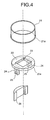
- the inner lid member 20 is made of a resin material such as plastic similarly to the outer lid member 10. As shown in FIGS. 3 and 4 , the inner lid member 20 has an inner lid main body 21 and a top plate 22.
- the inner lid main body 21 is cylindrical in shape though having a smaller diameter than the outer lid member 10 (more specifically, the outer lid main body 11).
- a stopper 21a is formed along a circumferential direction and projects radially outward. The stopper 21a, which will be described in detail later, serves to restrict the movement of the inner lid member 20 by abutting against the retainer 11b of the outer lid member 10.
- the top plate 22 has a disk-like shape having an outer diameter which is substantially the same as the inner diameter of the inner lid main body 21.
- the top plate 22 is arranged inside the inner lid main body 21 at an upper end portion thereof. More specifically, an end surface 22a of the top plate 22 is bonded to the inner surface of the upper end portion of the inner lid main body 21.
- the top plate 22 has a rectangular second opening 23 in the center. The second opening 23 is arranged opposite to the first opening 13 of the outer lid member 10, and the detail will be described later. Further, the top plate 22 has a pair of support plates 24 projecting downward from the second opening 23. Each of the support plates 24 has a cutout 25 widening downward on the lower edge. Further, a spacer 26 is fitted to the top plate 22 so as to project downward similarly to the support plate 24.
- the rotating drum 30 is made, for example, of a resin material such as plastic, and has a substantially columnar shape as shown in FIG. 5 .
- a support pin 31 is arranged so as to project along a central axis of the rotating drum 30 from each of end surfaces 30a and 30b.
- the outer diameter of the support pin 31 is such that it fits to the width of the cutout 25 of the support plate 24 of the inner lid member 20.
- a through hole 32 is formed in a direction perpendicular to the central axis, in other words, in a vertical direction of FIG. 5 .
- oval engaging grooves 33 are formed respectively to extend in the same radially outward direction from the support pin 31.
- the width of the engaging groove 33 is such that it fits to the outer diameter of the engaging pin 15 of the engaging plate 14 of the outer lid member 10.
- FIG. 6 is a schematic sectional side view of the lid structure according to one embodiment of the present invention in a fitted state.
- FIG. 6 will be referred to as appropriate in the description of the lid structure.
- the outer lid member 10 is fitted to the reagent container 1 with the fitting portion 11a fitted onto the upper portion of the reagent container 1.
- the base plate 12 is arranged at an open end of the reagent container 1 so that the first opening 13 of the base plate 12 corresponds to the opening 2 of the reagent container 1.
- the rotating drum 30 is arranged so that the central axis thereof matches with the horizontal axis, and the engaging pin 15 of the outer lid member 10 is inserted into the engaging groove 33 of the rotating drum 30.
- the rotating drum 30 engages with the outer lid member 10.
- the support pin 31 of the rotating drum 30 is inserted into the cutout 25 of the inner lid member 20 so that the rotating drum 30 engages with the inner lid member 20.
- the inner lid member 20 is moved in the direction of an arrow of FIG. 6 (i.e., leftward) while the rotating drum 30 remains engaged with the inner lid member 20.
- the inner lid member 20 is pressed downward so that the inner lid member 20 is inserted into the outer lid member 10.
- FIG. 7 is a perspective view of the lid structure when the inner lid member is positioned at the top dead center
- FIG. 8 is a perspective view of an interior of the lid structure shown in FIG. 7
- FIG. 9 is a sectional side view of the lid structure
- FIG. 10 is a sectional view along line A-A of FIG. 9 .
- the through hole 32 of the rotating drum 30 is arranged in the direction of a horizontal axis, and a side circumferential portion 30c of the rotating drum 30 is inserted in the second opening 23 of the inner lid member 20 which opposes to the first opening 13 of the outer lid member 10.
- the communication between the first opening 13 and the second opening 23 is cut.
- the opening 2 of the reagent container 1 is in a closed state.
- the engaging groove 33 on each of the end surfaces 30a and 30b of the rotating drum 30 extends in a direction from the central axis of the rotating drum 30 to obliquely downward, radially outward direction.
- the lid structure which keeps the opening 2 of the reagent container 1 in a closed state as described above can bring the opening 2 of the reagent container 1 into an open state as follows.
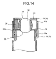
- FIG. 11 is a perspective view of the lid structure when the inner lid member is positioned at the bottom dead center
- FIG. 12 is a perspective view of the interior of the lid structure shown in FIG. 11
- FIG. 13 is a sectional side view of the lid structure
- FIG. 14 is a sectional view along line B-B of FIG. 13 .
- the inner lid member 20 When the inner lid member 20 is released from the pressure, the inner lid member 20 moves upward from the bottom dead center according to the pressing force of the coil spring. In other words, the inner lid member 20 performs a closing operation.
- the rotating drum 30 As a whole moves upward keeping the support pin 31 engaged with the cutout 25.
- the engaging pin 15 presses the edge portion of the engaging groove 33 to make the rotating drum 30 rotate around the horizontal axis in an opposite direction from the direction mentioned earlier.
- the inner lid member 20 stops the closing operation and reaches the top dead center (see FIGS. 7 to 11 ). Then, as described above, the through hole 32 of the rotating drum 30 runs along the direction of the horizontal axis, and the side circumferential portion 30c enters the second opening 23 of the inner lid member 20. Thus, the communication between the first opening 13 and the second opening 23 is cut, and the opening 2 of the reagent container 1 is brought into a closed state.
- the opening 2 of the reagent container 1 can be opened and closed many times.
- the engaging pin 15 of the outer lid member 10, the engaging groove 33 and the support pin 31 of the rotating drum 30, and the cutout 25 of the inner lid member 20 configure an engaging unit which rotates the rotating drum 30 to make the first opening 13 and the second opening 23 communicated with each other through the through hole 32 and thereby bringing the opening 2 of the reagent container 1 into an open state when the inner lid member 20 performs the opening operation, whereas rotates the rotating drum 30 to cut the communication between the first opening 13 and the second opening 23 to bring the opening 2 into a closed state when the inner lid member 20 performs the closing operation.
- the reagent container 1 having the above-described lid structure When the reagent container 1 having the above-described lid structure is placed in a predetermined analyzer so that a reagent is employed for the biological analysis, an element of the analyzer presses the inner lid member 20 to realize the opening operation, and the rotating drum 30 rotates around the horizontal axis. Then, the inner lid member 20 comes to the bottom dead center, and the second opening 23 of the inner lid member 20 is communicated with the first opening 13 of the outer lid member 10 through the through hole 32, whereby the opening 2 of the reagent container 1 is brought into an open state. Then, a probe or the like is inserted into the reagent container 1 through the opening 2 in the open state so that the reagent can be collected and used for the analysis.
- the element releases the inner lid member 20 from the pressure to make the inner lid member 20 perform the closing operation according to the pressing force of the coil spring.
- the rotating drum 30 rotates, and when the inner lid member 20 reaches the top dead center, the communication between the second opening 23 of the inner lid member 20 and the first opening 13 of the outer lid member 10 is cut, whereby the opening 2 of the reagent container 1 is brought into a closed state.
- the lid structure according to the embodiment rotates the rotating drum 30 to make the first opening 13 and the second opening 23 communicated with each other via the through hole 32 when the inner lid member 20 performs the downward opening operation so that the opening 2 of the reagent container 1 is brought into an open state, whereas the lid structure rotates the rotating drum 30 to make the communication between the first opening 13 and the second opening 23 cut when the inner lid member 20 performs the upward closing operation so that the opening 2 is brought into a closed state.
- the vertical movements of the inner lid member 20 can realize the opening and closing of the opening 2.
- the reagent container 1 having the above-described lid structure is placed in a predetermined analyzer, the reagent container 1 can be arranged without any consideration to the space where the inner lid member 20 moves.
- the lid structure of one reagent container 1 does not interfere with the lid structure of another adjacent reagent container 1 even when plural reagent containers 1 are placed in the analyzer.
- the lid structure of the reagent container according to the present invention is advantageous in that it can open and close the opening 2 of the reagent container 1 with a simple structure and that it has excellent space utilization efficiency.
- the above-described lid structure has a smaller number of parts in comparison with the conventional lid structure which moves in the horizontal direction, and cost can be reduced.
- the lid structure of the reagent container according to the present invention is useful, for example, for opening and closing the opening of a reagent container holding a reagent.
Landscapes
- Physics & Mathematics (AREA)
- Health & Medical Sciences (AREA)
- Life Sciences & Earth Sciences (AREA)
- Chemical & Material Sciences (AREA)
- Analytical Chemistry (AREA)
- Biochemistry (AREA)
- General Health & Medical Sciences (AREA)
- General Physics & Mathematics (AREA)
- Immunology (AREA)
- Pathology (AREA)
- Engineering & Computer Science (AREA)
- Mechanical Engineering (AREA)
- Automatic Analysis And Handling Materials Therefor (AREA)
- Closures For Containers (AREA)
- Containers And Packaging Bodies Having A Special Means To Remove Contents (AREA)
Applications Claiming Priority (2)
| Application Number | Priority Date | Filing Date | Title |
|---|---|---|---|
| JP2005226997A JP4642587B2 (ja) | 2005-08-04 | 2005-08-04 | 試薬用容器の蓋構造 |
| PCT/JP2006/315323 WO2007015526A1 (fr) | 2005-08-04 | 2006-08-02 | Structure de couvercle de receptacle a reactif |
Publications (1)
| Publication Number | Publication Date |
|---|---|
| EP1912070A1 true EP1912070A1 (fr) | 2008-04-16 |
Family
ID=37708806
Family Applications (1)
| Application Number | Title | Priority Date | Filing Date |
|---|---|---|---|
| EP06782192A Pending EP1912070A1 (fr) | 2005-08-04 | 2006-08-02 | Structure de couvercle de receptacle a reactif |
Country Status (4)
| Country | Link |
|---|---|
| US (1) | US7648037B2 (fr) |
| EP (1) | EP1912070A1 (fr) |
| JP (1) | JP4642587B2 (fr) |
| WO (1) | WO2007015526A1 (fr) |
Cited By (1)
| Publication number | Priority date | Publication date | Assignee | Title |
|---|---|---|---|---|
| EP2199802A4 (fr) * | 2008-02-07 | 2011-10-05 | Arkray Inc | Contenant et contenant d'analyse l'utilisant |
Families Citing this family (10)
| Publication number | Priority date | Publication date | Assignee | Title |
|---|---|---|---|---|
| JP2007040899A (ja) * | 2005-08-04 | 2007-02-15 | Olympus Corp | 試料容器 |
| JP2007039103A (ja) * | 2005-08-04 | 2007-02-15 | Olympus Corp | 試料容器 |
| US8251263B2 (en) | 2008-03-24 | 2012-08-28 | Mary Kay Inc. | Container caps and systems |
| MX2011000976A (es) * | 2008-07-24 | 2011-07-29 | Mary Kay Inc | Tapas y sistemas para contenedor. |
| WO2011085068A2 (fr) * | 2010-01-06 | 2011-07-14 | Union Street Brand Packaging Llc | Distributeur doseur |
| FI20116059A7 (fi) | 2011-10-28 | 2013-04-29 | Thermo Fisher Scientific Oy | Reagenssipullo, järjestelmä, menetelmä ja laite suljinkorkkien ja vastaavien käsittelemiseksi |
| ES2770423T3 (es) * | 2013-03-13 | 2020-07-01 | Abbott Lab | Tapas enchavetadas para recipientes y sistemas relacionados con las mismas |
| US10526117B2 (en) | 2016-08-05 | 2020-01-07 | The Hillman Group, Inc. | Lid assembly and related container for fasteners |
| EP3440968A1 (fr) | 2017-08-09 | 2019-02-13 | Koninklijke Philips N.V. | Récipient de liquide conçu pour être utilisé avec un dispositif d'écumage de liquide comprenant un conduit d'aspiration de liquide |
| US10896750B2 (en) * | 2018-04-24 | 2021-01-19 | Arrix, Inc. | Systems and methods for medication management |
Family Cites Families (14)
| Publication number | Priority date | Publication date | Assignee | Title |
|---|---|---|---|---|
| US1577235A (en) * | 1924-08-19 | 1926-03-16 | Sodastream Ltd | Device for use in removing measured quantities of the contents of bottles and like containers |
| US1982917A (en) * | 1932-11-05 | 1934-12-04 | Charles R Lothrop | Dispensing apparatus |
| GB448119A (en) * | 1934-11-30 | 1936-06-02 | James Rest | Improvements in or relating to closures for bottles, collapsible tubes and like containers |
| US3703249A (en) * | 1970-05-08 | 1972-11-21 | Edward Benjamin Middleton | Rotatable opening container closure |
| JPS51146981A (en) * | 1975-06-10 | 1976-12-16 | Kondo Hiroatsu | Lid of vessel |
| JPS6252147A (ja) | 1985-08-29 | 1987-03-06 | Asahi Glass Co Ltd | 改良された安全ガラス |
| JPS6252147U (fr) * | 1985-09-17 | 1987-04-01 | ||
| ES2127806T3 (es) * | 1991-12-06 | 1999-05-01 | James W Holley | Recipiente y metodo para contener sustancias. |
| US6152189A (en) * | 1993-03-30 | 2000-11-28 | Isco, Inc. | Sampler |
| US6161712A (en) * | 1996-07-22 | 2000-12-19 | Becton Dickinson And Company | Ball and socket closure |
| US6032813A (en) * | 1997-09-12 | 2000-03-07 | Becton, Dickinson And Company | Ball and socket closure for specimen collection container incorporating an integral flexible seal |
| US6350415B1 (en) * | 1997-09-12 | 2002-02-26 | Becton, Dickinson And Company | Ball and socket closure for specimen collection container incorporating a dimple locking mechanism |
| DE19746169A1 (de) | 1997-10-18 | 1999-04-22 | Dade Behring Marburg Gmbh | Kappe für einen Reagenzbehälter |
| JP2006189346A (ja) * | 2005-01-06 | 2006-07-20 | Olympus Corp | 薬液容器、薬液保冷庫および培養処理装置 |
-
2005
- 2005-08-04 JP JP2005226997A patent/JP4642587B2/ja not_active Expired - Fee Related
-
2006
- 2006-08-02 WO PCT/JP2006/315323 patent/WO2007015526A1/fr not_active Ceased
- 2006-08-02 EP EP06782192A patent/EP1912070A1/fr active Pending
-
2008
- 2008-02-04 US US12/025,379 patent/US7648037B2/en not_active Expired - Fee Related
Non-Patent Citations (1)
| Title |
|---|
| See references of WO2007015526A1 * |
Cited By (1)
| Publication number | Priority date | Publication date | Assignee | Title |
|---|---|---|---|---|
| EP2199802A4 (fr) * | 2008-02-07 | 2011-10-05 | Arkray Inc | Contenant et contenant d'analyse l'utilisant |
Also Published As
| Publication number | Publication date |
|---|---|
| JP2007040898A (ja) | 2007-02-15 |
| WO2007015526A1 (fr) | 2007-02-08 |
| US7648037B2 (en) | 2010-01-19 |
| JP4642587B2 (ja) | 2011-03-02 |
| US20080296297A1 (en) | 2008-12-04 |
Similar Documents
| Publication | Publication Date | Title |
|---|---|---|
| US7648037B2 (en) | Lid structure of reagent container | |
| US10807090B2 (en) | Apparatus, devices, and methods for manipulating deformable fluid vessels | |
| EP0820812B1 (fr) | Dispositif de prélèvement d'échantillons | |
| US7785537B2 (en) | Sample container | |
| US20120195808A1 (en) | Reagent kit for analyzing apparatus | |
| US20090022631A1 (en) | Sample container | |
| JP6336791B2 (ja) | 自動分析装置における試薬容器受容位置のための閉鎖システム | |
| JP3956294B2 (ja) | 試薬容器のキャップ及び試薬の蒸発等の防止法 | |
| JP6381910B2 (ja) | 閉止装置 | |
| JP2006091030A (ja) | 自動分析装置 | |
| WO2008041341A1 (fr) | Capuchon de récipient de réactif et récipient de réactif | |
| KR100392774B1 (ko) | 진공용기의 밸브장치 | |
| JPH09210884A (ja) | X線回折装置用サンプルホルダ | |
| JP2009120200A (ja) | キャップの装着装置、取り外し装置、装着方法並びに取り外し方法 | |
| JP4421602B2 (ja) | 小型容器の栓体開閉装置 | |
| EP1923705A1 (fr) | Élément de scellement, capuchon de récipient de réactif, et récipient de réactif | |
| US12582980B2 (en) | Fluid handling device and fluid handling system | |
| JP7676975B2 (ja) | 容器保持ラックおよび前処理装置 | |
| JP2025040505A (ja) | 試料収納ラックシステム | |
| EP2199802B1 (fr) | Contenant et son utilisation dans une analyse | |
| HK1114668A (en) | Seal member, cap of reagent container, and reagent container |
Legal Events
| Date | Code | Title | Description |
|---|---|---|---|
| PUAI | Public reference made under article 153(3) epc to a published international application that has entered the european phase |
Free format text: ORIGINAL CODE: 0009012 |
|
| 17P | Request for examination filed |
Effective date: 20080130 |
|
| AK | Designated contracting states |
Kind code of ref document: A1 Designated state(s): DE FR GB |
|
| DAX | Request for extension of the european patent (deleted) | ||
| RBV | Designated contracting states (corrected) |
Designated state(s): DE FR GB |
|
| D18D | Application deemed to be withdrawn (deleted) | ||
| STAA | Information on the status of an ep patent application or granted ep patent |
Free format text: STATUS: THE APPLICATION IS DEEMED TO BE WITHDRAWN |
|
| 18D | Application deemed to be withdrawn |
Effective date: 20100301 |