EP1912238A1 - Interrupteur de circuit comprenant un détecteur de courant à fil de dérivation et un processeur ayant une fonction prédictive de surcharge thermique - Google Patents
Interrupteur de circuit comprenant un détecteur de courant à fil de dérivation et un processeur ayant une fonction prédictive de surcharge thermique Download PDFInfo
- Publication number
- EP1912238A1 EP1912238A1 EP07020075A EP07020075A EP1912238A1 EP 1912238 A1 EP1912238 A1 EP 1912238A1 EP 07020075 A EP07020075 A EP 07020075A EP 07020075 A EP07020075 A EP 07020075A EP 1912238 A1 EP1912238 A1 EP 1912238A1
- Authority
- EP
- European Patent Office
- Prior art keywords
- circuit interrupter
- circuit
- shunt wire
- function
- separable contacts
- Prior art date
- Legal status (The legal status is an assumption and is not a legal conclusion. Google has not performed a legal analysis and makes no representation as to the accuracy of the status listed.)
- Granted
Links
- 230000006870 function Effects 0.000 claims abstract description 39
- 230000007246 mechanism Effects 0.000 claims abstract description 15
- 230000009993 protective function Effects 0.000 claims abstract description 5
- 238000004519 manufacturing process Methods 0.000 description 7
- 230000007935 neutral effect Effects 0.000 description 4
- 230000001681 protective effect Effects 0.000 description 4
- 239000004020 conductor Substances 0.000 description 3
- 238000001816 cooling Methods 0.000 description 3
- 238000000034 method Methods 0.000 description 3
- 239000007787 solid Substances 0.000 description 3
- 238000010438 heat treatment Methods 0.000 description 2
- 238000012886 linear function Methods 0.000 description 2
- 230000008569 process Effects 0.000 description 2
- 230000004044 response Effects 0.000 description 2
- 239000007858 starting material Substances 0.000 description 2
- 241000233805 Phoenix Species 0.000 description 1
- 230000003321 amplification Effects 0.000 description 1
- 230000008901 benefit Effects 0.000 description 1
- 239000003990 capacitor Substances 0.000 description 1
- 230000008878 coupling Effects 0.000 description 1
- 238000010168 coupling process Methods 0.000 description 1
- 238000005859 coupling reaction Methods 0.000 description 1
- 238000010586 diagram Methods 0.000 description 1
- 230000006872 improvement Effects 0.000 description 1
- 238000009413 insulation Methods 0.000 description 1
- 238000013507 mapping Methods 0.000 description 1
- 239000000463 material Substances 0.000 description 1
- 238000012986 modification Methods 0.000 description 1
- 230000004048 modification Effects 0.000 description 1
- 238000003199 nucleic acid amplification method Methods 0.000 description 1
- 230000002085 persistent effect Effects 0.000 description 1
- 230000002277 temperature effect Effects 0.000 description 1
- 230000036413 temperature sense Effects 0.000 description 1
Images

Classifications
-
- H—ELECTRICITY
- H01—ELECTRIC ELEMENTS
- H01H—ELECTRIC SWITCHES; RELAYS; SELECTORS; EMERGENCY PROTECTIVE DEVICES
- H01H71/00—Details of the protective switches or relays covered by groups H01H73/00 - H01H83/00
- H01H71/10—Operating or release mechanisms
- H01H71/12—Automatic release mechanisms with or without manual release
- H01H71/14—Electrothermal mechanisms
- H01H71/16—Electrothermal mechanisms with bimetal element
- H01H71/162—Electrothermal mechanisms with bimetal element with compensation for ambient temperature
-
- H—ELECTRICITY
- H01—ELECTRIC ELEMENTS
- H01H—ELECTRIC SWITCHES; RELAYS; SELECTORS; EMERGENCY PROTECTIVE DEVICES
- H01H83/00—Protective switches, e.g. circuit-breaking switches, or protective relays operated by abnormal electrical conditions otherwise than solely by excess current
- H01H83/20—Protective switches, e.g. circuit-breaking switches, or protective relays operated by abnormal electrical conditions otherwise than solely by excess current operated by excess current as well as by some other abnormal electrical condition
-
- H—ELECTRICITY
- H01—ELECTRIC ELEMENTS
- H01H—ELECTRIC SWITCHES; RELAYS; SELECTORS; EMERGENCY PROTECTIVE DEVICES
- H01H83/00—Protective switches, e.g. circuit-breaking switches, or protective relays operated by abnormal electrical conditions otherwise than solely by excess current
- H01H83/20—Protective switches, e.g. circuit-breaking switches, or protective relays operated by abnormal electrical conditions otherwise than solely by excess current operated by excess current as well as by some other abnormal electrical condition
- H01H2083/201—Protective switches, e.g. circuit-breaking switches, or protective relays operated by abnormal electrical conditions otherwise than solely by excess current operated by excess current as well as by some other abnormal electrical condition the other abnormal electrical condition being an arc fault
-
- H—ELECTRICITY
- H01—ELECTRIC ELEMENTS
- H01H—ELECTRIC SWITCHES; RELAYS; SELECTORS; EMERGENCY PROTECTIVE DEVICES
- H01H83/00—Protective switches, e.g. circuit-breaking switches, or protective relays operated by abnormal electrical conditions otherwise than solely by excess current
- H01H83/20—Protective switches, e.g. circuit-breaking switches, or protective relays operated by abnormal electrical conditions otherwise than solely by excess current operated by excess current as well as by some other abnormal electrical condition
- H01H2083/206—Protective switches, e.g. circuit-breaking switches, or protective relays operated by abnormal electrical conditions otherwise than solely by excess current operated by excess current as well as by some other abnormal electrical condition with thermal shunt trip
Definitions
- Circuit interrupters include, for example, circuit breakers, contactors, motor starters, motor controllers, other load controllers and receptacles having a trip mechanism. Circuit breakers are generally old and well known in the art. Examples of circuit breakers are disclosed in U.S. Patent Nos. 5,260,676 ; and 5,293,522 .
- Circuit breakers are used to protect electrical circuitry from damage due to an overcurrent condition, such as an overload condition or a relatively high level short circuit or fault condition.
- an overcurrent condition such as an overload condition or a relatively high level short circuit or fault condition.
- small circuit breakers commonly referred to as miniature circuit breakers, used for residential and light commercial applications, such protection is typically provided by a thermal-magnetic trip device.
- This trip device includes a bimetal which is heated and bends in response to a persistent overcurrent condition. The bimetal, in turn, unlatches a spring powered operating mechanism which opens the separable contacts of the circuit breaker to interrupt current flow in the protected power system.
- An armature which is attracted by the sizable magnetic forces generated by a short circuit or fault, also unlatches, or trips, the operating mechanism.
- Bimetals do a good job of simulating thermal cooling of power conductors. The bimetal trips a circuit breaker when its temperature reaches a certain predetermined value. Most of today's circuit breakers are not ambient temperature compensated.
- UL 489 is a molded case circuit breaker standard that controls tripping characteristics. For a circuit breaker rated at, for example, 30 A or less, the following performance is required at three different current levels relative to the rated current:
- Analog circuits can simulate cooling using charge stored on a capacitor, which is simply reset to a fixed thermal level after a trip. See, for example, U.S. Patent No. 5,418,677 .
- Some analog circuits may use the temperature of an internal shunt for tripping, but this technique suffers from ambient temperature calibration issues or inaccuracies at the, above, 135% must trip setting of UL 489.
- circuit interrupter including a processor having a thermal overload predictive function, and a shunt wire structured to measure current flowing through separable contacts for the thermal overload predictive function.
- a circuit interrupter comprises: separable contacts; an operating mechanism structured to open and close the separable contacts; a processor including a thermal overload predictive function; and a shunt wire in series with the separable contacts and being structured to measure current flowing through the separable contacts for the thermal overload predictive function.
- the processor may further include an arc fault circuit interrupter function, and the shunt wire may also measure the current flowing through the separable contacts for the arc fault circuit interrupter function.
- the processor may further include a non-linear ambient temperature compensation function applied to the thermal overload predictive function.
- the thermal overload predictive function may include a diode temperature sensor cooperating with the shunt wire, and a nonvolatile memory saving ambient calibration information for the diode temperature sensor.
- the diode temperature sensor may be proximate the shunt wire.
- a circuit interrupter comprises: separable contacts; an operating mechanism structured to open and close the separable contacts; a processor including a thermal overload predictive function and an arc fault circuit interrupter function; and a shunt wire in series with the separable contacts and being structured to measure current flowing through the separable contacts for both of the thermal overload predictive function and the arc fault circuit interrupter function.
- the invention is described in association with a miniature circuit breaker, although the invention is applicable to a wide range of circuit interrupters.
- FIG. 1 shows a circuit interrupter, such as a miniature circuit breaker 2, including a protective electronic circuit 4 having a processor, such as microprocessor ( ⁇ P) 6.
- a protective electronic circuit 4 having a processor, such as microprocessor ( ⁇ P) 6.
- ⁇ P microprocessor
- an electronic ground fault protection function 16 may also be included if a ground fault (GF) sensing current transformer (CT) (not shown) is added with appropriate analog signal amplification (not shown) for input by the ⁇ P 6.
- GF ground fault
- CT current transformer
- the protective electronic circuit 4 and, more particularly, the ⁇ P 6, may include one or both of an arc fault protection circuit and a ground fault protection circuit.
- arc fault detectors are disclosed, for instance, in U.S. Patent No. 5,224,006 , with a preferred type described in U.S. Patent No. 5,691,869 , which is hereby incorporated by reference herein.
- ground fault detectors are disclosed in U.S. Patent Nos. 5,293,522 ; 5,260,676 ; 4,081,852 ; and 3,736,468 , which are hereby incorporated by reference herein.
- the example electronic circuit 4 provides a "thermal overload" predictive function 17 through the ⁇ P 6.
- a temperature sensor e.g., without limitation, a diode (D1) 18, which is driven by a suitable predetermined low level current from current source 20
- D1 diode
- R1 8 shunt wire
- a suitable power supply 22 (e.g., alternating current to direct current) supplies power to the current source 20 and a microcomputer ( ⁇ C) 28.
- the ⁇ C 28 includes the ⁇ P 6 and a nonvolatile (NV) memory 24, and may also optionally include an ambient temperature sensing circuit (not shown), although such a circuit is not required.
- the ⁇ P 6 drives an SCR 26 that energizes the coil of the trip solenoid 12 to trip open the separable contacts 14 through the operating mechanism 10.
- the separable contacts 14 are electrically connected in series with the shunt wire (R1) 8 between a line terminal 30 and a load terminal 32.
- the power supply 22 is powered from a line-to-neutral voltage between the line terminal 30 and a line neutral terminal 34, which is electrically connected to a load neutral terminal 36.
- the ambient temperature and the corresponding forward voltage of the diode (D1) 18, as measured by ⁇ P 6 from the anode of diode (D1) 18 with no current in the shunt wire (R1) 8, are measured and saved in the ⁇ C NV memory 24.
- Diodes, such as diode (D1) 18, have a very predictable and stable negative voltage temperature coefficient (e.g., without limitation, about -2.2 mV/8C) when biased with a suitable small fixed current ( e . g ., without limitation, on the order of about 100 ⁇ A) from the example current source 20.
- the shunt wire (R1) 8 is selected to thermally match the UL 489 protection points of 135% and 200%.
- the shunt wire (R1) 8 is selected to be about the same wire gauge as that of the power circuit (not shown) being protected, but generally with a relatively higher temperature insulation rating, in order that its thermal mass slows the temperature rise of that shunt. For example, when 200% current is applied, the temperature of the shunt wire (R1) 8 (and the corresponding voltage of the diode (D1) 18) reaches the trip temperature, which trips the circuit breaker 2 based upon the sensed temperature (and the corresponding sensed voltage), in about 15 seconds which is within the UL 489 limits.
- T trip is the shunt temperature rise above ambient when tripping occurs. Equations 1 and 2 show T trip for the ultimate (chosen or 115%) trip point and the 200% trip point, respectively.
- Equation 3 shows T trip for the 135% trip point.
- R t R * Irated * 1.35 2 *
- RtCt 95 seconds and solving Equations 1 and 3 for t@135% yields RtCt ⁇ 123 seconds.
- the nominal trip time at 200% rated current is 38 seconds and the nominal trip time at 135% rated current is about 123 seconds.
- a conventional bimetal trips a conventional circuit breaker (not shown) at a certain temperature, To, at, for example, 115% of rated current.
- the power circuit ambient For thermal overload conditions at about 135% of rated current, the power circuit ambient somewhat tracks the temperature rise of the shunt wire (R1) 8. Therefore, if ambient temperature compensation is to be used, then it needs to be a non-linear function desensitizing the ambient temperature effects.
- the circuit breaker 2 may be hot because its load center (not shown) is located in Phoenix, Arizona on the south side of a house (not shown) on a sunny day.
- high ambient temperatures do not necessarily mean that the power circuit conductor (not shown), which is electrically connected to the load terminal 32 and in series with the shunt wire (R1) 8, to be protected is also hot.
- ambient compensation if used, should only be enabled at temperatures above about 40°C, which is the listed breaker operating temperature, and be just sufficient to prevent nuisance tripping.
- the desired non-linear function is easily incorporated into the ⁇ P protective functions 7,16 with, for example, a predetermined table lookup in the NV memory 24.
- the ambient temperature is below 40°C as measured by a circuit (not shown) either internal to the ⁇ C 28 or on the ⁇ C circuit board, then no compensation is made. However, if the ambient temperature is 65°C, then the trip level temperature (To) may be raised by about a 20°C setpoint limit, since some of the ambient temperature rise may be due to the load current power dissipation in components other than, but also including, the shunt wire 8.
- the temperature rise of the shunt wire (R1) 8 is proportional to the power dissipation (i.e., (Ishunt) 2 Rshunt) and thus V X will be related to T X or the I 2 R heating of the wires (i.e., the shunt wire (R1) 8 and also the power conductor or wire to be protected).
- Table 1 defines a set of thermal overload conditions for a circuit breaker (not shown) as defined by UL 489 (molded case circuit breaker standard) section 7.1.2 "Calibration Tests”.
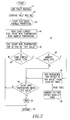
- a trip routine 40 for the ⁇ C 28 of Figure 1 is shown.
- the trip routine 40 may include one or both of an arc fault trip routine 41 and a ground fault trip routine 42.
- the start of an electronic thermal protection routine which provides a thermal overload predictive function.
- the load current current sense
- the shunt wire temperature temperature sense
- the ambient temperature are read.
- the load current is determined from the voltage of the shunt wire (R1) 8.
- the shunt wire temperature is determined from the forward voltage of the diode (D1) 18.
- the ambient temperature may be determined from a suitable ambient temperature sensor (not shown) or, optionally, is ignored. In the latter case, steps 48 and 56 are not employed.
- step 50 is executed as was discussed above.
- the "Trip Value” is preferably determined experimentally for a reference circuit (not shown) using a reference diode (not shown). Then, that experimental “trip value” is preferably adjusted at the time of manufacture of a particular circuit interrupter by measuring the forward voltage of the diode (D1) 18 at 258C. This assumes that: (1) the diode forward voltage at 258C may vary from diode to diode; and (2) the diode forward voltage temperature coefficient will be uniform from diode to diode. Also, the temperature of the shunt wire 8 at the trip point is a fixed number.
- both the bimetal and the shunt wire dissipate about the same amount of power.
- eliminating the bimetal halves the power dissipation.
- ⁇ P 6 with the NV memory 24 enables the use of the internal shunt wire (R1) 8 to sense overload and cooling off conditions.
- This ⁇ P 6 has the benefit of being able to simply measure and store ambient calibration values at the time of manufacture of the electronic circuit 4.
- a non-linear response e.g., without limitation, a lookup table
- ambient temperatures is stored in the NV memory 24 to more accurately match the UL 489 135% tripping requirements.
- separable contacts 14 are disclosed, suitable solid state separable contacts may be employed.
- the disclosed circuit breaker 2 includes a suitable circuit interrupter mechanism, such as the separable contacts 14 that are opened and closed by the operating mechanism 10, although the invention is applicable to a wide range of circuit interruption mechanisms (e.g., without limitation, solid state or FET switches; contactor contacts) and/or solid state based control/protection devices (e.g., without limitation, drives; soft-starters).
- circuit interruption mechanisms e.g., without limitation, solid state or FET switches; contactor contacts
- solid state based control/protection devices e.g., without limitation, drives; soft-starters.
- circuit interrupter such as a miniature circuit breaker 4 protective electronic circuit 6 processor, such as microprocessor ( ⁇ P) 7 arc fault circuit interrupter (AFCI) function 8 shunt wire (R1) 10 circuit breaker operating mechanism 12 trip solenoid 14 separable contacts 16 electronic ground fault protection function 17 "thermal overload” predictive function 18 diode (D1) 20 current source 22 power supply 24 nonvolatile (NV) memory 26 SCR 28 ⁇ C 30 line terminal 32 load terminal 34 line neutral terminal 36 load neutral terminal 38 non-linear ambient temperature compensation function 40 trip routine 41 arc fault trip routine 42 ground fault trip routine 43 step 44 step 45 step 46 step 48 step 52 step 54 step 56 step 58 look-up table
Landscapes
- Emergency Protection Circuit Devices (AREA)
- Driving Mechanisms And Operating Circuits Of Arc-Extinguishing High-Tension Switches (AREA)
Applications Claiming Priority (1)
| Application Number | Priority Date | Filing Date | Title |
|---|---|---|---|
| US11/549,164 US7675721B2 (en) | 2006-10-13 | 2006-10-13 | Circuit interrupter including a shunt wire current sensor and a processor having a thermal overload predictive function |
Publications (2)
| Publication Number | Publication Date |
|---|---|
| EP1912238A1 true EP1912238A1 (fr) | 2008-04-16 |
| EP1912238B1 EP1912238B1 (fr) | 2012-10-10 |
Family
ID=38924476
Family Applications (1)
| Application Number | Title | Priority Date | Filing Date |
|---|---|---|---|
| EP07020075A Not-in-force EP1912238B1 (fr) | 2006-10-13 | 2007-10-12 | Interrupteur de circuit comprenant un détecteur de courant à fil de dérivation et un processeur ayant une fonction prédictive de surcharge thermique |
Country Status (6)
| Country | Link |
|---|---|
| US (1) | US7675721B2 (fr) |
| EP (1) | EP1912238B1 (fr) |
| AU (1) | AU2007221959B2 (fr) |
| BR (1) | BRPI0714077A2 (fr) |
| CA (1) | CA2606996C (fr) |
| MX (1) | MX2007012789A (fr) |
Cited By (3)
| Publication number | Priority date | Publication date | Assignee | Title |
|---|---|---|---|---|
| WO2011067593A3 (fr) * | 2009-12-02 | 2011-11-10 | Gigle Networks Limited | Appareil de mesure du courant |
| WO2013178259A1 (fr) * | 2012-05-30 | 2013-12-05 | Siemens Aktiengesellschaft | Dispositif de protection contre les surintensités |
| FR3157653A1 (fr) | 2023-12-21 | 2025-06-27 | Hager-Electro Sas | Appareillage électrique de protection contre au moins un défaut de type surcharge |
Families Citing this family (14)
| Publication number | Priority date | Publication date | Assignee | Title |
|---|---|---|---|---|
| JP4992572B2 (ja) * | 2007-06-26 | 2012-08-08 | ブラザー工業株式会社 | 電力供給遮断回路及び液滴吐出装置 |
| US7869178B2 (en) * | 2007-11-12 | 2011-01-11 | Honeywell International Inc. | Augmentation of ambient temperature and free convection effects in thermal circuit breaker trip curve approximations |
| JP5055177B2 (ja) * | 2008-03-24 | 2012-10-24 | 矢崎総業株式会社 | 負荷回路の保護装置 |
| DE102008039334B4 (de) * | 2008-08-22 | 2016-01-14 | Airbus Defence and Space GmbH | Verfahren und Vorrichtung zum optimierten Energiemanagement |
| US8159803B2 (en) * | 2009-12-07 | 2012-04-17 | Ward Michael J | Heat actuated interrupter receptacle |
| US20110141635A1 (en) * | 2009-12-10 | 2011-06-16 | Fabian Steven D | Thermally protected GFCI |
| BR112013001974A2 (pt) * | 2010-07-26 | 2018-08-28 | Tyco Electronics Corp | circuito controlador que inclui um conversor de energia de modo de comutação e religador automático que utiliza o mesmo |
| CN102280321A (zh) * | 2011-06-10 | 2011-12-14 | 上海电机学院 | 一种轻载过热保护断路器 |
| US9030795B2 (en) | 2012-12-21 | 2015-05-12 | Eaton Corporation | Apparatus and method of adaptive electronic overload protection |
| KR101922553B1 (ko) * | 2015-11-17 | 2018-11-27 | 주식회사 엘지화학 | 바이메탈을 이용한 릴레이 독립 제어 시스템 및 방법 |
| DE102015121194A1 (de) * | 2015-12-04 | 2017-06-08 | Infineon Technologies Ag | Vorrichtung mit integriertem Schutzverlauf und Verfahren |
| US9728348B2 (en) * | 2015-12-21 | 2017-08-08 | Eaton Corporation | Electrical switching apparatus with electronic trip unit |
| US11004620B2 (en) * | 2019-03-18 | 2021-05-11 | Eaton Intelligent Power Limited | Circuit interrupter and method of determining contact wear based upon temperature |
| JP7523971B2 (ja) * | 2020-07-01 | 2024-07-29 | 株式会社東芝 | 監視装置 |
Citations (10)
| Publication number | Priority date | Publication date | Assignee | Title |
|---|---|---|---|---|
| GB728774A (en) * | 1952-05-29 | 1955-04-27 | Leeds & Northrup Co | Improvements in ambient-temperature compensated device for measuring the intensity of radiant energy |
| US3736468A (en) | 1971-06-30 | 1973-05-29 | Westinghouse Electric Corp | Ground fault interrupter apparatus |
| US4081852A (en) | 1974-10-03 | 1978-03-28 | Westinghouse Electric Corporation | Ground fault circuit breaker |
| US4517543A (en) * | 1983-12-01 | 1985-05-14 | Eaton Corporation | SME overcurrent protective apparatus having ambient temperature compensation |
| US5224006A (en) | 1991-09-26 | 1993-06-29 | Westinghouse Electric Corp. | Electronic circuit breaker with protection against sputtering arc faults and ground faults |
| US5260676A (en) | 1991-03-27 | 1993-11-09 | Westinghouse Electric Corp. | Dual wound trip solenoid |
| US5293522A (en) | 1992-09-11 | 1994-03-08 | Westinghouse Electric Company | Ground fault circuit breaker with test spring/contacts directly mounted to test circuit of printed circuit board |
| US5418677A (en) * | 1990-12-28 | 1995-05-23 | Eaton Corporation | Thermal modeling of overcurrent trip during power loss |
| US5691869A (en) | 1995-06-06 | 1997-11-25 | Eaton Corporation | Low cost apparatus for detecting arcing faults and circuit breaker incorporating same |
| US6225883B1 (en) * | 2000-02-15 | 2001-05-01 | Eaton Corporation | Circuit breaker with latch and toggle mechanism operating in perpendicular planes |
Family Cites Families (12)
| Publication number | Priority date | Publication date | Assignee | Title |
|---|---|---|---|---|
| US3991391A (en) | 1974-01-29 | 1976-11-09 | Westinghouse Electric Corporation | Circuit interrupter with electromagnetic opening means |
| US4358810A (en) | 1981-01-21 | 1982-11-09 | Westinghouse Electric Corp. | Circuit breaker with alarm |
| US4487063A (en) * | 1983-07-11 | 1984-12-11 | General Motors Corporation | Solid state mass air flow sensor |
| DE3643221A1 (de) * | 1986-12-18 | 1988-06-30 | Braun Ag | Gleichstromsteller |
| US5436784A (en) * | 1993-08-11 | 1995-07-25 | Schweitzer Engineering Laboratories, Inc. | Motor protection relay using thermal models |
| US5459630A (en) * | 1993-09-15 | 1995-10-17 | Eaton Corporation | Self testing circuit breaker ground fault and sputtering arc trip unit |
| JP3384522B2 (ja) * | 1996-07-30 | 2003-03-10 | 矢崎総業株式会社 | スイッチング装置 |
| US5835320A (en) | 1997-05-28 | 1998-11-10 | General Electric Company | Digital circuit interrupter thermal protection circuit |
| US5936817A (en) * | 1998-05-11 | 1999-08-10 | Eaton Corporation | Electrical switching apparatus employing a circuit for selectively enabling and disabling a close actuator mechanism |
| US6137386A (en) | 1999-08-18 | 2000-10-24 | Eaton Corporation | Circuit breaker with trip unit mounted tripping plunger and latch therefore |
| US6876532B2 (en) | 2002-04-29 | 2005-04-05 | Eaton Corporation | Circuit interrupter trip unit |
| US7508642B2 (en) * | 2005-07-14 | 2009-03-24 | Honeywell International Inc. | Method and apparatus applying virtual Δt trip criterion in power distribution |
-
2006
- 2006-10-13 US US11/549,164 patent/US7675721B2/en active Active
-
2007
- 2007-10-11 BR BRPI0714077-0A patent/BRPI0714077A2/pt not_active IP Right Cessation
- 2007-10-12 CA CA2606996A patent/CA2606996C/fr active Active
- 2007-10-12 EP EP07020075A patent/EP1912238B1/fr not_active Not-in-force
- 2007-10-12 AU AU2007221959A patent/AU2007221959B2/en not_active Ceased
- 2007-10-12 MX MX2007012789A patent/MX2007012789A/es active IP Right Grant
Patent Citations (10)
| Publication number | Priority date | Publication date | Assignee | Title |
|---|---|---|---|---|
| GB728774A (en) * | 1952-05-29 | 1955-04-27 | Leeds & Northrup Co | Improvements in ambient-temperature compensated device for measuring the intensity of radiant energy |
| US3736468A (en) | 1971-06-30 | 1973-05-29 | Westinghouse Electric Corp | Ground fault interrupter apparatus |
| US4081852A (en) | 1974-10-03 | 1978-03-28 | Westinghouse Electric Corporation | Ground fault circuit breaker |
| US4517543A (en) * | 1983-12-01 | 1985-05-14 | Eaton Corporation | SME overcurrent protective apparatus having ambient temperature compensation |
| US5418677A (en) * | 1990-12-28 | 1995-05-23 | Eaton Corporation | Thermal modeling of overcurrent trip during power loss |
| US5260676A (en) | 1991-03-27 | 1993-11-09 | Westinghouse Electric Corp. | Dual wound trip solenoid |
| US5224006A (en) | 1991-09-26 | 1993-06-29 | Westinghouse Electric Corp. | Electronic circuit breaker with protection against sputtering arc faults and ground faults |
| US5293522A (en) | 1992-09-11 | 1994-03-08 | Westinghouse Electric Company | Ground fault circuit breaker with test spring/contacts directly mounted to test circuit of printed circuit board |
| US5691869A (en) | 1995-06-06 | 1997-11-25 | Eaton Corporation | Low cost apparatus for detecting arcing faults and circuit breaker incorporating same |
| US6225883B1 (en) * | 2000-02-15 | 2001-05-01 | Eaton Corporation | Circuit breaker with latch and toggle mechanism operating in perpendicular planes |
Cited By (4)
| Publication number | Priority date | Publication date | Assignee | Title |
|---|---|---|---|---|
| WO2011067593A3 (fr) * | 2009-12-02 | 2011-11-10 | Gigle Networks Limited | Appareil de mesure du courant |
| US8884607B2 (en) | 2009-12-02 | 2014-11-11 | Broadcom Corporation | Current measuring apparatus |
| WO2013178259A1 (fr) * | 2012-05-30 | 2013-12-05 | Siemens Aktiengesellschaft | Dispositif de protection contre les surintensités |
| FR3157653A1 (fr) | 2023-12-21 | 2025-06-27 | Hager-Electro Sas | Appareillage électrique de protection contre au moins un défaut de type surcharge |
Also Published As
| Publication number | Publication date |
|---|---|
| MX2007012789A (es) | 2009-02-17 |
| EP1912238B1 (fr) | 2012-10-10 |
| CA2606996A1 (fr) | 2008-04-13 |
| US7675721B2 (en) | 2010-03-09 |
| CA2606996C (fr) | 2015-07-07 |
| AU2007221959B2 (en) | 2012-04-05 |
| BRPI0714077A2 (pt) | 2009-06-16 |
| US20080088991A1 (en) | 2008-04-17 |
| AU2007221959A1 (en) | 2008-05-01 |
Similar Documents
| Publication | Publication Date | Title |
|---|---|---|
| EP1912238B1 (fr) | Interrupteur de circuit comprenant un détecteur de courant à fil de dérivation et un processeur ayant une fonction prédictive de surcharge thermique | |
| AU2007206650B2 (en) | Circuit breaker and method for sensing current indirectly from bimetal voltage and determining bimetal temperature and corrected temperature dependent bimetal resistance | |
| EP3161837B1 (fr) | Ensemble à déclenchement thermique et interrupteur de circuit le comprenant | |
| EP1359655A2 (fr) | Déclencheur de disjoncteur | |
| JP2003100196A (ja) | 電子回路遮断器 | |
| EP3161849B1 (fr) | Interrupteur de circuit comprenant un ensemble déclencheur thermique et une bobine de rogowski à carte de circuits imprimés | |
| US10622801B2 (en) | Circuit interrupter with temperature compensation and method of operating a circuit interrupter | |
| EP3271933B1 (fr) | Unité de déclenchement électronique alimentée par transformateurs de courant et disjoncteur le comprenant | |
| US9030795B2 (en) | Apparatus and method of adaptive electronic overload protection | |
| US5966281A (en) | Circuit breaker with thermal sensing unit | |
| WO2014137440A1 (fr) | Unité d'affichage conçue pour afficher des informations de déclenchement et interrupteur de circuit la comprenant | |
| EP4179558B1 (fr) | Détection de courant de surcharge dans un dispositif d'interruption de circuit | |
| US20050219032A1 (en) | Method and apparatus for providing electrical protection to a protected circuit | |
| Aronstein | Temperature sensitivity of residential molded case circuit breakers | |
| GB2564127A (en) | Voltage transformer with overload protection | |
| Strobel | Equipment and Apparatus Circuit Protection | |
| Lagree et al. | Un-powered thermal memory protection for circuit breakers |
Legal Events
| Date | Code | Title | Description |
|---|---|---|---|
| PUAI | Public reference made under article 153(3) epc to a published international application that has entered the european phase |
Free format text: ORIGINAL CODE: 0009012 |
|
| AK | Designated contracting states |
Kind code of ref document: A1 Designated state(s): AT BE BG CH CY CZ DE DK EE ES FI FR GB GR HU IE IS IT LI LT LU LV MC MT NL PL PT RO SE SI SK TR |
|
| AX | Request for extension of the european patent |
Extension state: AL BA HR MK RS |
|
| 17P | Request for examination filed |
Effective date: 20081014 |
|
| 17Q | First examination report despatched |
Effective date: 20081117 |
|
| AKX | Designation fees paid |
Designated state(s): DE FR GB IT |
|
| GRAP | Despatch of communication of intention to grant a patent |
Free format text: ORIGINAL CODE: EPIDOSNIGR1 |
|
| GRAS | Grant fee paid |
Free format text: ORIGINAL CODE: EPIDOSNIGR3 |
|
| GRAA | (expected) grant |
Free format text: ORIGINAL CODE: 0009210 |
|
| AK | Designated contracting states |
Kind code of ref document: B1 Designated state(s): DE FR GB IT |
|
| REG | Reference to a national code |
Ref country code: GB Ref legal event code: FG4D |
|
| REG | Reference to a national code |
Ref country code: DE Ref legal event code: R096 Ref document number: 602007025964 Country of ref document: DE Effective date: 20121213 |
|
| PLBE | No opposition filed within time limit |
Free format text: ORIGINAL CODE: 0009261 |
|
| STAA | Information on the status of an ep patent application or granted ep patent |
Free format text: STATUS: NO OPPOSITION FILED WITHIN TIME LIMIT |
|
| 26N | No opposition filed |
Effective date: 20130711 |
|
| REG | Reference to a national code |
Ref country code: DE Ref legal event code: R097 Ref document number: 602007025964 Country of ref document: DE Effective date: 20130711 |
|
| PGFP | Annual fee paid to national office [announced via postgrant information from national office to epo] |
Ref country code: GB Payment date: 20130925 Year of fee payment: 7 |
|
| PGFP | Annual fee paid to national office [announced via postgrant information from national office to epo] |
Ref country code: FR Payment date: 20130924 Year of fee payment: 7 Ref country code: DE Payment date: 20131031 Year of fee payment: 7 |
|
| PGFP | Annual fee paid to national office [announced via postgrant information from national office to epo] |
Ref country code: IT Payment date: 20131022 Year of fee payment: 7 |
|
| REG | Reference to a national code |
Ref country code: DE Ref legal event code: R119 Ref document number: 602007025964 Country of ref document: DE |
|
| GBPC | Gb: european patent ceased through non-payment of renewal fee |
Effective date: 20141012 |
|
| PG25 | Lapsed in a contracting state [announced via postgrant information from national office to epo] |
Ref country code: GB Free format text: LAPSE BECAUSE OF NON-PAYMENT OF DUE FEES Effective date: 20141012 Ref country code: DE Free format text: LAPSE BECAUSE OF NON-PAYMENT OF DUE FEES Effective date: 20150501 |
|
| REG | Reference to a national code |
Ref country code: FR Ref legal event code: ST Effective date: 20150630 |
|
| PG25 | Lapsed in a contracting state [announced via postgrant information from national office to epo] |
Ref country code: FR Free format text: LAPSE BECAUSE OF NON-PAYMENT OF DUE FEES Effective date: 20141031 Ref country code: IT Free format text: LAPSE BECAUSE OF NON-PAYMENT OF DUE FEES Effective date: 20141012 |