EP1912285A1 - Appareil électrique ou électronique - Google Patents
Appareil électrique ou électronique Download PDFInfo
- Publication number
- EP1912285A1 EP1912285A1 EP07019704A EP07019704A EP1912285A1 EP 1912285 A1 EP1912285 A1 EP 1912285A1 EP 07019704 A EP07019704 A EP 07019704A EP 07019704 A EP07019704 A EP 07019704A EP 1912285 A1 EP1912285 A1 EP 1912285A1
- Authority
- EP
- European Patent Office
- Prior art keywords
- connector
- leg
- housing
- locking element
- plug
- Prior art date
- Legal status (The legal status is an assumption and is not a legal conclusion. Google has not performed a legal analysis and makes no representation as to the accuracy of the status listed.)
- Granted
Links
- 230000007704 transition Effects 0.000 claims abstract description 9
- 239000011324 bead Substances 0.000 claims description 4
- 239000012780 transparent material Substances 0.000 claims description 4
- 230000000284 resting effect Effects 0.000 abstract 1
- 230000000712 assembly Effects 0.000 description 2
- 238000000429 assembly Methods 0.000 description 2
- 239000004020 conductor Substances 0.000 description 2
- 238000000034 method Methods 0.000 description 2
- 241000233805 Phoenix Species 0.000 description 1
- 238000010276 construction Methods 0.000 description 1
- 238000011109 contamination Methods 0.000 description 1
- 230000002950 deficient Effects 0.000 description 1
- 238000006073 displacement reaction Methods 0.000 description 1
- 238000005516 engineering process Methods 0.000 description 1
- 230000007613 environmental effect Effects 0.000 description 1
- 238000003780 insertion Methods 0.000 description 1
- 230000037431 insertion Effects 0.000 description 1
- 238000004806 packaging method and process Methods 0.000 description 1
- 230000035939 shock Effects 0.000 description 1
Images


Classifications
-
- H—ELECTRICITY
- H01—ELECTRIC ELEMENTS
- H01R—ELECTRICALLY-CONDUCTIVE CONNECTIONS; STRUCTURAL ASSOCIATIONS OF A PLURALITY OF MUTUALLY-INSULATED ELECTRICAL CONNECTING ELEMENTS; COUPLING DEVICES; CURRENT COLLECTORS
- H01R9/00—Structural associations of a plurality of mutually-insulated electrical connecting elements, e.g. terminal strips or terminal blocks; Terminals or binding posts mounted upon a base or in a case; Bases therefor
- H01R9/22—Bases, e.g. strip, block, panel
- H01R9/24—Terminal blocks
- H01R9/2491—Terminal blocks structurally associated with plugs or sockets
-
- H—ELECTRICITY
- H01—ELECTRIC ELEMENTS
- H01R—ELECTRICALLY-CONDUCTIVE CONNECTIONS; STRUCTURAL ASSOCIATIONS OF A PLURALITY OF MUTUALLY-INSULATED ELECTRICAL CONNECTING ELEMENTS; COUPLING DEVICES; CURRENT COLLECTORS
- H01R13/00—Details of coupling devices of the kinds covered by groups H01R12/70 or H01R24/00 - H01R33/00
- H01R13/62—Means for facilitating engagement or disengagement of coupling parts or for holding them in engagement
- H01R13/629—Additional means for facilitating engagement or disengagement of coupling parts, e.g. aligning or guiding means, levers, gas pressure electrical locking indicators, manufacturing tolerances
- H01R13/633—Additional means for facilitating engagement or disengagement of coupling parts, e.g. aligning or guiding means, levers, gas pressure electrical locking indicators, manufacturing tolerances for disengagement only
- H01R13/6335—Additional means for facilitating engagement or disengagement of coupling parts, e.g. aligning or guiding means, levers, gas pressure electrical locking indicators, manufacturing tolerances for disengagement only comprising a handle
-
- H—ELECTRICITY
- H01—ELECTRIC ELEMENTS
- H01R—ELECTRICALLY-CONDUCTIVE CONNECTIONS; STRUCTURAL ASSOCIATIONS OF A PLURALITY OF MUTUALLY-INSULATED ELECTRICAL CONNECTING ELEMENTS; COUPLING DEVICES; CURRENT COLLECTORS
- H01R13/00—Details of coupling devices of the kinds covered by groups H01R12/70 or H01R24/00 - H01R33/00
- H01R13/62—Means for facilitating engagement or disengagement of coupling parts or for holding them in engagement
- H01R13/639—Additional means for holding or locking coupling parts together, after engagement, e.g. separate keylock, retainer strap
-
- H—ELECTRICITY
- H01—ELECTRIC ELEMENTS
- H01R—ELECTRICALLY-CONDUCTIVE CONNECTIONS; STRUCTURAL ASSOCIATIONS OF A PLURALITY OF MUTUALLY-INSULATED ELECTRICAL CONNECTING ELEMENTS; COUPLING DEVICES; CURRENT COLLECTORS
- H01R9/00—Structural associations of a plurality of mutually-insulated electrical connecting elements, e.g. terminal strips or terminal blocks; Terminals or binding posts mounted upon a base or in a case; Bases therefor
- H01R9/22—Bases, e.g. strip, block, panel
- H01R9/24—Terminal blocks
- H01R9/26—Clip-on terminal blocks for side-by-side rail- or strip-mounting
- H01R9/2625—Clip-on terminal blocks for side-by-side rail- or strip-mounting with built-in electrical component
- H01R9/2666—Clip-on terminal blocks for side-by-side rail- or strip-mounting with built-in electrical component with built-in test-points
-
- H—ELECTRICITY
- H05—ELECTRIC TECHNIQUES NOT OTHERWISE PROVIDED FOR
- H05K—PRINTED CIRCUITS; CASINGS OR CONSTRUCTIONAL DETAILS OF ELECTRIC APPARATUS; MANUFACTURE OF ASSEMBLAGES OF ELECTRICAL COMPONENTS
- H05K7/00—Constructional details common to different types of electric apparatus
- H05K7/14—Mounting supporting structure in casing or on frame or rack
- H05K7/1462—Mounting supporting structure in casing or on frame or rack for programmable logic controllers [PLC] for automation or industrial process control
- H05K7/1468—Mechanical features of input/output (I/O) modules
- H05K7/1469—Terminal blocks for connecting sensors
Definitions
- the invention relates to an electrical or electronic device, in particular for placement on a mounting rail, with a housing, arranged in the housing electronics, in particular a printed circuit board, and with at least one connector, wherein in the housing at least one plug-in connection for receiving a connector is formed and the plug connection has at least one contact element which is connected to the electronics, so that at least one electrical line can be connected to the electronics with the aid of the plug connector.
- the invention also relates to a housing for such an electrical or electronic device.
- Modular electronic components require a functionally appropriate packaging, which allow different adjustment and control functions and as simple as possible but must be safe and reliable mountable.
- a functionally appropriate packaging which allow different adjustment and control functions and as simple as possible but must be safe and reliable mountable.
- the individual electronic devices are usually mounted directly on a mounting rail and preferably connected via a bus system with each other and with a controller.
- the housings consist of an upper housing part and a lower housing part, wherein the upper housing part has connections for electrical lines, the connections are connected via plug contacts to the lower housing part and the lower housing part connects to a bus system.
- the individual housing are designed so that a plurality of housing adjacent to each other on a mounting rail can be latched, so that a plurality of housing together form a housing block.
- the individual adjacent housing or the individual adjacent electronic devices are preferably electrically contactable with each other.
- connection of electrical lines to the electronic device is done simply by means of connectors that can be plugged into arranged on the front sides of the housing plug-in connections.
- the plug connectors can in particular have screw connections, spring-cage connections or cutting connections, so-called insulation-displacement connection (IDC) connections for connecting the electrical lines.
- IDC insulation-displacement connection
- the individual connectors have different numbers of poles, so that a corresponding number of electrical lines are connected to the individual electronic devices can; typical electronic devices have 8, 12, 16, 24, 32 or 48 poles, which are then usually arranged on both end sides of the electronic device, at least two connectors one above the other.
- the advantage of the connector over a fixed wiring, for example by means of screw or spring connections on the electronic device is to first connect the electrical leads to the connectors and then plug the ready wired connectors into the connectors.
- the connector when replacing a defective device only the connector must be pulled out of the connectors, without the individual electrical lines must be solved.
- this flexibility also leads to the fact that it can come with shocks to an unwanted loosening or partial loosening of the connector from the plug connections.
- there is a risk that a connector during assembly is not completely plugged into a plug-in connection, so that it may cause loose contacts.
- the present invention is therefore based on the object, an electrical or electronic device or a housing for such a device described above in such a way that it can be used in practice even more reliable, the handling should not be affected or only slightly.
- a locking element for locking an inserted connector is pivotally mounted, that the locking element is approximately U-shaped, covering with an inserted connector U-back one the front edge of an inserted connector cross-over, designed as a latching element first U-leg and a rear edge of an inserted connector engages behind the second U-leg, wherein the locking element has a pivot axis in the transition region of the U-back to the second U-leg Leg is arranged.
- the inventive arrangement of a pivotable locking element on the housing initially has the ability to fix an inserted connector so reliable in its position that an accidental release of the connector is reliably prevented even in harsh environmental conditions and strong vibrations.
- the locking element is approximately U-shaped and has a plugged connector plugging U-back and a front edge of the inserted connector cross-first U-legs, also a simple check the correct, fully inserted position of the connector is ensured in the plug connection because the locking element is pivotable into the locking position only when the connector is fully inserted into the connector.
- the locking element also fulfills the function of an ejector while intentionally loosening or pulling out a connector from the plug connection.
- the second U-leg which engages behind a rear edge of the connector in the inserted state of a connector.
- the locking member is pivoted from the locked position, the connector is first unlocked so that it can be pulled out of the connector.
- the locking element is further pivoted, the free end of the second U-leg presses against a rear edge of the connector, whereby it is pushed out of the plug-in connection or pushed out.
- the locking element thus has a double function; On the one hand it serves as a lock for an inserted connector, on the other hand, it can also be used as an ejector.
- the electrical or electronic device generally has at least one connector on both end faces, often even two staggered connectors, ie a total of four connectors, the individual connectors being designed to connect a plurality of electrical lines.
- a corresponding number of locking elements is pivotally mounted on the housing, wherein the width of the individual locking elements corresponds to the width of the individual connectors, so that the U-back of each locking element completely covers the inserted connector.
- the pivotable arrangement of a locking element on the housing is effected simply by the fact that two laterally projecting pivot pins are formed on the locking element, which are mounted in corresponding recesses in the housing.
- the recesses for the trunnions may be recesses in the opposite housing walls as well as through openings.
- the recesses are open at the top, so that a locking element can be easily fixed by snapping the pivot in the correspondingly formed recesses on the housing.
- the locking element and the connector are at least partially matched in their geometry.
- the two U-legs of the locking element are each designed so that they fulfill their function as well as possible and safe.
- the first U-leg of the locking element is designed as a latching hook, which engages behind a formed on the front edge of the connector bead in the locked state.
- an externally accessible handle portion is formed, which is preferably formed in the transition region of the U-back to the first U-leg.
- the handle portion may for example be formed as a protruding edge, so that the locking element can be easily pivoted with a finger from the locked position.
- a test plug is inserted through the opening in the connector.
- a receptacle for a marking strip is formed in the U-back of the locking element, wherein the receptacle is preferably arranged on the underside of the U-back and at least the U-back of the locking element consists of a transparent material.
- a corresponding label can of course also be glued to the top of the U-back or inserted into a corresponding receptacle.
- the present invention relates in addition to an electrical or electronic device and an electronics housing with at least two connectors for connecting electrical conductors, wherein in the housing at least two plug-in connections for receiving the connector are formed and the plug-in connections each have at least one contact element, via the plug-in connections are connected to one another or to an electronics arranged in the housing, so that at least two electrical lines can be connected to one another or connected to the electronics with the aid of the plug-in connectors.
- the object underlying the invention is also achieved in that in each case a locking element for locking an inserted connector is pivotally arranged in the region above the plug-in connections, that the locking elements are approximately U-shaped, with a plug connector plugged U- Back, one the front edge of an inserted connector cross-over, designed as a latching element first U-leg and a trailing edge of an inserted connector engages behind U-leg, wherein the locking elements have a pivot axis which is arranged in the transition region of the U-back to second U-legs.
- the arrangement and design of the locking element is basically independent of whether or how the electronics arranged in the housing is formed. Basically, it is also possible that the electronic housing is used only for connecting at least two conductors connected to the two connectors. The electronics housing then corresponds essentially to its function of a conventional terminal block.
- the electronics housing according to the invention preferably consists of a mountable on a support rail base part and a releasably connectable to the base part upper part, wherein between the base part and the upper part a particular lockable locking is provided.
- This locking can consist for example of a resilient latching arm on the upper housing part and a corresponding latching hook on the base part.
- the base part is aufschwenkbar on the mounting rail, with a second latchable locking is provided for releasably connecting the base part with the support rails, preferably a spring-loaded, slidably held on the base part latch to one-sided Has locking the mounting rail.
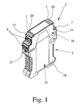
- FIGS. 1 to 4 show a preferred exemplary embodiment of an electronic device 1 which can be placed on a mounting rail (not shown here).
- the electronic device 1 has a housing 2, an arranged in the housing 2 - only in Figs. 5 and 6 indicated - electronics in the form of a printed circuit board 3 and a total of four connectors 4.
- the individual connectors 4 each have four screw terminals for connecting four electrical lines, wherein two connectors 4 are arranged one above the other like a staircase on each end face of the electronic device.
- each plug-in terminals 5 are formed corresponding to the four connectors 4 for receiving the connector 4, wherein the each plug-in terminals 5 each have four contact elements 6, which are fixedly connected to the circuit board 3.
- the individual screw terminals of the connector 4 each contact a contact element 6, so that four electrical lines can be connected to the circuit board 3 by means of a connector 4.
- the individual plug-in connections 4 can also have spring-cage connections or cutting connections instead of the screw connections shown here.
- a respective locking element 7 is pivotally mounted on the housing 2 in the region above each plug connection 5, with the aid of which a completely plugged into a plug connection 5 plug connector 4 can be locked, as in Fig. 1 in all four connectors 4 is shown.
- the individual locking elements 7 are approximately U-shaped, so that they each have an U-back 8 covering an inserted plug-in connector 4, a first U-engaging cross-section of the front edge 9 of an inserted connector 4.
- the locking elements 7 each have two laterally projecting pivot pins 13 which are mounted in corresponding recesses 14 in the side walls of the housing 2. Characterized in that the recesses 14 are open at the top, the individual locking elements 7 can be easily pressed with their pivot 13 in the recesses 14.
- the pivot pins 13 forming the axis of rotation are in the transition region of the U-back 8 to the second U-leg 12.
- the U-back 8 of the locking element 7 has such a length that it completely covers a fully inserted connector 4.
- the locking elements 7 can thus also be referred to as lockable hinged lid.
- both the first U-leg 10 and the second U-leg 12 is formed shorter than the U-back 8, wherein the first U-leg 10, which is designed as a latching element, is arranged at an angle of about 90 ° to the U-back 8, while the second U-leg 12 to the U-back 8 has an angle of about 130 °.
- a bead 15 is formed on the upper front edge 9 of the connector 4, which is overlapped in the locked state by a formed at the free end of the first U-leg 10 of the locking element 7 corresponding latching hook 16.
- this has a readily accessible from the outside handle portion 17, so that the locking element 7 can be easily pivoted with a finger from the fully locked position shown in Fig. 5 at the lower locking element 7 in an unlocked position, as is shown in the upper locking member 7 in Fig. 5. If the connector 4 are pulled out of the plug connection 5, then the locking element 7 can be pivoted even further in the direction of the arrow 18 shown in FIGS.
- the locking member 7 thus serves not only to lock a fully inserted connector 4 but also as an ejector in the intentional pulling out of the connector 4 from the plug connection. 5
- a total of four openings 20 for a test plug 21 are formed in the U-back 8 of the locking element 7, so that contacted in the locked state of the connector 4 by means of a test plug 21, the individual screw terminals of the connector 4 can be.
- the U-back 8 of the locking element 7 is used to mark the individual connectors 4 and the individual terminals of the connector 4.
- a receptacle 22 is formed for a marking strip 23 in the U-back 8, wherein in a preferred embodiment, the locking element 7 in total, but at least the U-back 8 is made of a transparent material, so that the receptacle 22 for the identification strip 23 may be formed on the underside of the U-back 8.
- This has the advantage that the identification strip 23 is protected by the locking element 7 at the same time against damage or contamination.
- the housing 2 consists of a base part 25 which can be placed on a mounting rail and an upper part 26, wherein the upper part 26 can be released by means of a lockable latch 27 with the base part 25 connected is.
- a spring-loaded latch 28 is slidably held on the base part 25, which engages behind the support rail one side of the mounting rail after the pivoting of the base part 25.
Landscapes
- Engineering & Computer Science (AREA)
- Automation & Control Theory (AREA)
- Microelectronics & Electronic Packaging (AREA)
- Details Of Connecting Devices For Male And Female Coupling (AREA)
- Photoreceptors In Electrophotography (AREA)
- Developing Agents For Electrophotography (AREA)
- Lubricants (AREA)
Applications Claiming Priority (1)
| Application Number | Priority Date | Filing Date | Title |
|---|---|---|---|
| DE202006015897U DE202006015897U1 (de) | 2006-10-13 | 2006-10-13 | Elektrisches oder elektronisches Gerät |
Publications (2)
| Publication Number | Publication Date |
|---|---|
| EP1912285A1 true EP1912285A1 (fr) | 2008-04-16 |
| EP1912285B1 EP1912285B1 (fr) | 2011-12-14 |
Family
ID=37887465
Family Applications (1)
| Application Number | Title | Priority Date | Filing Date |
|---|---|---|---|
| EP07019704A Not-in-force EP1912285B1 (fr) | 2006-10-13 | 2007-10-09 | Appareil électrique ou électronique |
Country Status (5)
| Country | Link |
|---|---|
| EP (1) | EP1912285B1 (fr) |
| JP (1) | JP5096101B2 (fr) |
| CN (1) | CN101188333B (fr) |
| AT (1) | ATE537578T1 (fr) |
| DE (1) | DE202006015897U1 (fr) |
Cited By (1)
| Publication number | Priority date | Publication date | Assignee | Title |
|---|---|---|---|---|
| EP3644694A1 (fr) * | 2018-10-24 | 2020-04-29 | Radzikowski, Robert | Prise et terminal sur enceinte modulaire |
Families Citing this family (9)
| Publication number | Priority date | Publication date | Assignee | Title |
|---|---|---|---|---|
| DE202008015306U1 (de) * | 2008-11-19 | 2010-04-08 | Weidmüller Interface GmbH & Co. KG | Reihenklemmenanordnung mit Querverbindern und Prüfsteckern |
| DE102008058871B3 (de) * | 2008-11-26 | 2010-06-02 | Siemens Aktiengesellschaft | Beschriftungsträger für ein elektrisches Reiheneinbaugerät sowie elektrisches Reiheneinbaugerät |
| DE102011105157B4 (de) * | 2011-06-17 | 2019-01-03 | Phoenix Contact Gmbh & Co. Kg | Elektrisches Verbindungsmodul mit unterbrechbarem Stromkreis und Verfahren zum Erfassen einer Stromstärke |
| DE202012102325U1 (de) † | 2012-06-25 | 2012-07-17 | Wago Verwaltungsgesellschaft Mbh | Elektronikgerätegehäuse |
| DE102014116811A1 (de) * | 2014-11-18 | 2016-05-19 | Phoenix Contact Gmbh & Co. Kg | Reihenklemme |
| CN104916925A (zh) * | 2015-05-29 | 2015-09-16 | 上海友邦电子有限公司 | 一种与迷你隔离器快速连接的模块 |
| DE202015105393U1 (de) * | 2015-10-12 | 2017-01-13 | Weidmüller Interface GmbH & Co. KG | Anschlussvorrichtung mit einer Aufnahme für ein Steckmittel |
| DE102016004308A1 (de) * | 2016-04-12 | 2017-10-12 | E. Dold & Söhne KG | Elektronikbaugruppen-Gehäuseset |
| DE102016114295B4 (de) * | 2016-08-02 | 2026-01-08 | Phoenix Contact Gmbh & Co. Kg | Elektronikgehäuse |
Citations (4)
| Publication number | Priority date | Publication date | Assignee | Title |
|---|---|---|---|---|
| DE29603161U1 (de) * | 1996-02-22 | 1996-05-15 | Gebr. Merten Gmbh & Co Kg, 51643 Gummersbach | Abdeckung für ein elektrisches Gehäuse |
| DE29606759U1 (de) * | 1996-04-13 | 1996-06-27 | Klöckner-Moeller GmbH, 53115 Bonn | Mehrteiliges Gehäuse in Modulbauweise zur Aufnahme einer Leiterplatte |
| DE29713960U1 (de) | 1997-03-16 | 1997-12-04 | Phoenix Contact Gmbh & Co., 32825 Blomberg | Elektrisches oder elektronisches Gerät |
| US6811425B1 (en) | 2003-09-25 | 2004-11-02 | Excel Cell Electronic Co., Ltd. | Controller module responsive to input signals for controlling an electrical appliance |
Family Cites Families (3)
| Publication number | Priority date | Publication date | Assignee | Title |
|---|---|---|---|---|
| JP2879412B2 (ja) * | 1994-11-25 | 1999-04-05 | モレックス インコーポレーテッド | イジェクト機構付きコネクタ |
| EP0896504B2 (fr) * | 1997-08-05 | 2008-03-12 | Phoenix Contact GmbH & Co. KG | Appareil électrique ou électronique |
| DE10230292B3 (de) * | 2002-07-05 | 2004-01-08 | R. Stahl Schaltgeräte GmbH | Träger für Modulgehäuse |
-
2006
- 2006-10-13 DE DE202006015897U patent/DE202006015897U1/de not_active Expired - Lifetime
-
2007
- 2007-10-09 EP EP07019704A patent/EP1912285B1/fr not_active Not-in-force
- 2007-10-09 AT AT07019704T patent/ATE537578T1/de active
- 2007-10-12 CN CN200710199993.XA patent/CN101188333B/zh not_active Expired - Fee Related
- 2007-10-15 JP JP2007268296A patent/JP5096101B2/ja not_active Expired - Fee Related
Patent Citations (4)
| Publication number | Priority date | Publication date | Assignee | Title |
|---|---|---|---|---|
| DE29603161U1 (de) * | 1996-02-22 | 1996-05-15 | Gebr. Merten Gmbh & Co Kg, 51643 Gummersbach | Abdeckung für ein elektrisches Gehäuse |
| DE29606759U1 (de) * | 1996-04-13 | 1996-06-27 | Klöckner-Moeller GmbH, 53115 Bonn | Mehrteiliges Gehäuse in Modulbauweise zur Aufnahme einer Leiterplatte |
| DE29713960U1 (de) | 1997-03-16 | 1997-12-04 | Phoenix Contact Gmbh & Co., 32825 Blomberg | Elektrisches oder elektronisches Gerät |
| US6811425B1 (en) | 2003-09-25 | 2004-11-02 | Excel Cell Electronic Co., Ltd. | Controller module responsive to input signals for controlling an electrical appliance |
Non-Patent Citations (1)
| Title |
|---|
| LEITERPLATTENANSCHLUSS COMBICON, 2005, pages 378 - 387 |
Cited By (1)
| Publication number | Priority date | Publication date | Assignee | Title |
|---|---|---|---|---|
| EP3644694A1 (fr) * | 2018-10-24 | 2020-04-29 | Radzikowski, Robert | Prise et terminal sur enceinte modulaire |
Also Published As
| Publication number | Publication date |
|---|---|
| HK1118961A1 (en) | 2009-02-20 |
| JP2008098176A (ja) | 2008-04-24 |
| CN101188333A (zh) | 2008-05-28 |
| DE202006015897U1 (de) | 2007-03-08 |
| CN101188333B (zh) | 2011-04-13 |
| JP5096101B2 (ja) | 2012-12-12 |
| ATE537578T1 (de) | 2011-12-15 |
| EP1912285B1 (fr) | 2011-12-14 |
Similar Documents
| Publication | Publication Date | Title |
|---|---|---|
| EP1912285B1 (fr) | Appareil électrique ou électronique | |
| DE10045498C2 (de) | Elektrische Reihenklemme | |
| DE19710768C2 (de) | Elektrisches oder elektronisches Gerät | |
| EP1251590B1 (fr) | Borne électrique | |
| EP2839544B1 (fr) | Bornier de test | |
| EP0909122B1 (fr) | Appareil électrique | |
| EP3176879B1 (fr) | Borne électrique | |
| EP2107648B1 (fr) | Connecteur avec une plaque de support utilisée comme blindage | |
| DE102012104350A1 (de) | Prüf- und Anschlussvorrichtungsanordnung | |
| EP3021421A1 (fr) | Dispositif de raccordement pour cable multiconducteur | |
| EP3987616B1 (fr) | Module enfichable pour un appareillage modulaire et appareillage modulaire | |
| DE102006054647B4 (de) | Elektrische Steckverbinderkupplung | |
| DE102016112831A1 (de) | Anschlussklemme | |
| EP2425497B1 (fr) | Dispositif de fixation pour fixer une fiche de connexion à un boîtier de base | |
| DE102010047458A1 (de) | Anschlussklemme | |
| EP3698440B1 (fr) | Pince de fixation | |
| EP3061327B1 (fr) | Appareil électronique | |
| DE102022113144A1 (de) | Steckverbinder mit einer rasteinrichtung zur verriegelung einer steckverbindung mit einem gegensteckverbinder, gegensteckverbinder sowie anordnung mit einem steckverbinder und einem gegensteckverbinder | |
| EP3210261B1 (fr) | Module électronique | |
| DE102011089591B4 (de) | Adapter zum Koppeln eines Leistungsschalters mit einem Zusatzmodul | |
| DE102016114295B4 (de) | Elektronikgehäuse | |
| EP2262062B1 (fr) | Connecteur à fiches | |
| DE20019792U1 (de) | Steckverbinder-Gehäuse mit Kodiereinrichtung | |
| DE102008011217B4 (de) | Betätigungswerkzeug zum Anschließen eines isolierten Leiters | |
| DE202012104581U1 (de) | Anordnung aus zwei miteinander verriegelbaren, insbesondere elektrischen, Baugruppen |
Legal Events
| Date | Code | Title | Description |
|---|---|---|---|
| PUAI | Public reference made under article 153(3) epc to a published international application that has entered the european phase |
Free format text: ORIGINAL CODE: 0009012 |
|
| AK | Designated contracting states |
Kind code of ref document: A1 Designated state(s): AT BE BG CH CY CZ DE DK EE ES FI FR GB GR HU IE IS IT LI LT LU LV MC MT NL PL PT RO SE SI SK TR |
|
| AX | Request for extension of the european patent |
Extension state: AL BA HR MK RS |
|
| 17P | Request for examination filed |
Effective date: 20080829 |
|
| 17Q | First examination report despatched |
Effective date: 20081002 |
|
| AKX | Designation fees paid |
Designated state(s): AT BE BG CH CY CZ DE DK EE ES FI FR GB GR HU IE IS IT LI LT LU LV MC MT NL PL PT RO SE SI SK TR |
|
| GRAP | Despatch of communication of intention to grant a patent |
Free format text: ORIGINAL CODE: EPIDOSNIGR1 |
|
| GRAS | Grant fee paid |
Free format text: ORIGINAL CODE: EPIDOSNIGR3 |
|
| GRAA | (expected) grant |
Free format text: ORIGINAL CODE: 0009210 |
|
| AK | Designated contracting states |
Kind code of ref document: B1 Designated state(s): AT BE BG CH CY CZ DE DK EE ES FI FR GB GR HU IE IS IT LI LT LU LV MC MT NL PL PT RO SE SI SK TR |
|
| REG | Reference to a national code |
Ref country code: GB Ref legal event code: FG4D Free format text: NOT ENGLISH |
|
| REG | Reference to a national code |
Ref country code: CH Ref legal event code: EP |
|
| REG | Reference to a national code |
Ref country code: IE Ref legal event code: FG4D |
|
| REG | Reference to a national code |
Ref country code: DE Ref legal event code: R096 Ref document number: 502007008832 Country of ref document: DE Effective date: 20120209 |
|
| REG | Reference to a national code |
Ref country code: NL Ref legal event code: T3 |
|
| REG | Reference to a national code |
Ref country code: SE Ref legal event code: TRGR |
|
| PG25 | Lapsed in a contracting state [announced via postgrant information from national office to epo] |
Ref country code: LT Free format text: LAPSE BECAUSE OF FAILURE TO SUBMIT A TRANSLATION OF THE DESCRIPTION OR TO PAY THE FEE WITHIN THE PRESCRIBED TIME-LIMIT Effective date: 20111214 |
|
| LTIE | Lt: invalidation of european patent or patent extension |
Effective date: 20111214 |
|
| PG25 | Lapsed in a contracting state [announced via postgrant information from national office to epo] |
Ref country code: LV Free format text: LAPSE BECAUSE OF FAILURE TO SUBMIT A TRANSLATION OF THE DESCRIPTION OR TO PAY THE FEE WITHIN THE PRESCRIBED TIME-LIMIT Effective date: 20111214 Ref country code: SI Free format text: LAPSE BECAUSE OF FAILURE TO SUBMIT A TRANSLATION OF THE DESCRIPTION OR TO PAY THE FEE WITHIN THE PRESCRIBED TIME-LIMIT Effective date: 20111214 Ref country code: GR Free format text: LAPSE BECAUSE OF FAILURE TO SUBMIT A TRANSLATION OF THE DESCRIPTION OR TO PAY THE FEE WITHIN THE PRESCRIBED TIME-LIMIT Effective date: 20120315 |
|
| PG25 | Lapsed in a contracting state [announced via postgrant information from national office to epo] |
Ref country code: CY Free format text: LAPSE BECAUSE OF FAILURE TO SUBMIT A TRANSLATION OF THE DESCRIPTION OR TO PAY THE FEE WITHIN THE PRESCRIBED TIME-LIMIT Effective date: 20111214 |
|
| REG | Reference to a national code |
Ref country code: IE Ref legal event code: FD4D |
|
| PG25 | Lapsed in a contracting state [announced via postgrant information from national office to epo] |
Ref country code: IE Free format text: LAPSE BECAUSE OF FAILURE TO SUBMIT A TRANSLATION OF THE DESCRIPTION OR TO PAY THE FEE WITHIN THE PRESCRIBED TIME-LIMIT Effective date: 20111214 Ref country code: CZ Free format text: LAPSE BECAUSE OF FAILURE TO SUBMIT A TRANSLATION OF THE DESCRIPTION OR TO PAY THE FEE WITHIN THE PRESCRIBED TIME-LIMIT Effective date: 20111214 Ref country code: BG Free format text: LAPSE BECAUSE OF FAILURE TO SUBMIT A TRANSLATION OF THE DESCRIPTION OR TO PAY THE FEE WITHIN THE PRESCRIBED TIME-LIMIT Effective date: 20120314 Ref country code: IS Free format text: LAPSE BECAUSE OF FAILURE TO SUBMIT A TRANSLATION OF THE DESCRIPTION OR TO PAY THE FEE WITHIN THE PRESCRIBED TIME-LIMIT Effective date: 20120414 Ref country code: EE Free format text: LAPSE BECAUSE OF FAILURE TO SUBMIT A TRANSLATION OF THE DESCRIPTION OR TO PAY THE FEE WITHIN THE PRESCRIBED TIME-LIMIT Effective date: 20111214 Ref country code: SK Free format text: LAPSE BECAUSE OF FAILURE TO SUBMIT A TRANSLATION OF THE DESCRIPTION OR TO PAY THE FEE WITHIN THE PRESCRIBED TIME-LIMIT Effective date: 20111214 |
|
| PG25 | Lapsed in a contracting state [announced via postgrant information from national office to epo] |
Ref country code: RO Free format text: LAPSE BECAUSE OF FAILURE TO SUBMIT A TRANSLATION OF THE DESCRIPTION OR TO PAY THE FEE WITHIN THE PRESCRIBED TIME-LIMIT Effective date: 20111214 Ref country code: PT Free format text: LAPSE BECAUSE OF FAILURE TO SUBMIT A TRANSLATION OF THE DESCRIPTION OR TO PAY THE FEE WITHIN THE PRESCRIBED TIME-LIMIT Effective date: 20120416 Ref country code: PL Free format text: LAPSE BECAUSE OF FAILURE TO SUBMIT A TRANSLATION OF THE DESCRIPTION OR TO PAY THE FEE WITHIN THE PRESCRIBED TIME-LIMIT Effective date: 20111214 |
|
| PLBE | No opposition filed within time limit |
Free format text: ORIGINAL CODE: 0009261 |
|
| STAA | Information on the status of an ep patent application or granted ep patent |
Free format text: STATUS: NO OPPOSITION FILED WITHIN TIME LIMIT |
|
| PG25 | Lapsed in a contracting state [announced via postgrant information from national office to epo] |
Ref country code: DK Free format text: LAPSE BECAUSE OF FAILURE TO SUBMIT A TRANSLATION OF THE DESCRIPTION OR TO PAY THE FEE WITHIN THE PRESCRIBED TIME-LIMIT Effective date: 20111214 |
|
| 26N | No opposition filed |
Effective date: 20120917 |
|
| REG | Reference to a national code |
Ref country code: DE Ref legal event code: R097 Ref document number: 502007008832 Country of ref document: DE Effective date: 20120917 |
|
| BERE | Be: lapsed |
Owner name: PHOENIX CONTACT G.M.B.H. & CO. KG Effective date: 20121031 |
|
| PG25 | Lapsed in a contracting state [announced via postgrant information from national office to epo] |
Ref country code: ES Free format text: LAPSE BECAUSE OF FAILURE TO SUBMIT A TRANSLATION OF THE DESCRIPTION OR TO PAY THE FEE WITHIN THE PRESCRIBED TIME-LIMIT Effective date: 20120325 |
|
| PG25 | Lapsed in a contracting state [announced via postgrant information from national office to epo] |
Ref country code: MC Free format text: LAPSE BECAUSE OF NON-PAYMENT OF DUE FEES Effective date: 20121031 |
|
| REG | Reference to a national code |
Ref country code: CH Ref legal event code: PL |
|
| PG25 | Lapsed in a contracting state [announced via postgrant information from national office to epo] |
Ref country code: BE Free format text: LAPSE BECAUSE OF NON-PAYMENT OF DUE FEES Effective date: 20121031 Ref country code: CH Free format text: LAPSE BECAUSE OF NON-PAYMENT OF DUE FEES Effective date: 20121031 Ref country code: LI Free format text: LAPSE BECAUSE OF NON-PAYMENT OF DUE FEES Effective date: 20121031 |
|
| PG25 | Lapsed in a contracting state [announced via postgrant information from national office to epo] |
Ref country code: MT Free format text: LAPSE BECAUSE OF FAILURE TO SUBMIT A TRANSLATION OF THE DESCRIPTION OR TO PAY THE FEE WITHIN THE PRESCRIBED TIME-LIMIT Effective date: 20111214 |
|
| REG | Reference to a national code |
Ref country code: AT Ref legal event code: MM01 Ref document number: 537578 Country of ref document: AT Kind code of ref document: T Effective date: 20121031 |
|
| PG25 | Lapsed in a contracting state [announced via postgrant information from national office to epo] |
Ref country code: AT Free format text: LAPSE BECAUSE OF NON-PAYMENT OF DUE FEES Effective date: 20121031 |
|
| PGFP | Annual fee paid to national office [announced via postgrant information from national office to epo] |
Ref country code: FR Payment date: 20131028 Year of fee payment: 7 Ref country code: SE Payment date: 20131029 Year of fee payment: 7 Ref country code: GB Payment date: 20131029 Year of fee payment: 7 |
|
| PGFP | Annual fee paid to national office [announced via postgrant information from national office to epo] |
Ref country code: FI Payment date: 20131028 Year of fee payment: 7 Ref country code: NL Payment date: 20131028 Year of fee payment: 7 Ref country code: IT Payment date: 20131023 Year of fee payment: 7 |
|
| PG25 | Lapsed in a contracting state [announced via postgrant information from national office to epo] |
Ref country code: TR Free format text: LAPSE BECAUSE OF FAILURE TO SUBMIT A TRANSLATION OF THE DESCRIPTION OR TO PAY THE FEE WITHIN THE PRESCRIBED TIME-LIMIT Effective date: 20111214 |
|
| PG25 | Lapsed in a contracting state [announced via postgrant information from national office to epo] |
Ref country code: LU Free format text: LAPSE BECAUSE OF NON-PAYMENT OF DUE FEES Effective date: 20121009 |
|
| PG25 | Lapsed in a contracting state [announced via postgrant information from national office to epo] |
Ref country code: HU Free format text: LAPSE BECAUSE OF FAILURE TO SUBMIT A TRANSLATION OF THE DESCRIPTION OR TO PAY THE FEE WITHIN THE PRESCRIBED TIME-LIMIT Effective date: 20071009 |
|
| REG | Reference to a national code |
Ref country code: NL Ref legal event code: V1 Effective date: 20150501 |
|
| REG | Reference to a national code |
Ref country code: SE Ref legal event code: EUG |
|
| GBPC | Gb: european patent ceased through non-payment of renewal fee |
Effective date: 20141009 |
|
| PG25 | Lapsed in a contracting state [announced via postgrant information from national office to epo] |
Ref country code: FI Free format text: LAPSE BECAUSE OF NON-PAYMENT OF DUE FEES Effective date: 20141009 Ref country code: SE Free format text: LAPSE BECAUSE OF NON-PAYMENT OF DUE FEES Effective date: 20141010 Ref country code: GB Free format text: LAPSE BECAUSE OF NON-PAYMENT OF DUE FEES Effective date: 20141009 |
|
| REG | Reference to a national code |
Ref country code: FR Ref legal event code: ST Effective date: 20150630 |
|
| PG25 | Lapsed in a contracting state [announced via postgrant information from national office to epo] |
Ref country code: FR Free format text: LAPSE BECAUSE OF NON-PAYMENT OF DUE FEES Effective date: 20141031 Ref country code: NL Free format text: LAPSE BECAUSE OF NON-PAYMENT OF DUE FEES Effective date: 20150501 Ref country code: IT Free format text: LAPSE BECAUSE OF NON-PAYMENT OF DUE FEES Effective date: 20141009 |
|
| PGFP | Annual fee paid to national office [announced via postgrant information from national office to epo] |
Ref country code: DE Payment date: 20161109 Year of fee payment: 10 |
|
| REG | Reference to a national code |
Ref country code: DE Ref legal event code: R119 Ref document number: 502007008832 Country of ref document: DE |
|
| PG25 | Lapsed in a contracting state [announced via postgrant information from national office to epo] |
Ref country code: DE Free format text: LAPSE BECAUSE OF NON-PAYMENT OF DUE FEES Effective date: 20180501 |