EP1912309B1 - Gruppiergehäuse und derartige Verwendung - Google Patents
Gruppiergehäuse und derartige Verwendung Download PDFInfo
- Publication number
- EP1912309B1 EP1912309B1 EP07360043A EP07360043A EP1912309B1 EP 1912309 B1 EP1912309 B1 EP 1912309B1 EP 07360043 A EP07360043 A EP 07360043A EP 07360043 A EP07360043 A EP 07360043A EP 1912309 B1 EP1912309 B1 EP 1912309B1
- Authority
- EP
- European Patent Office
- Prior art keywords
- zone
- box
- motor
- power supply
- control
- Prior art date
- Legal status (The legal status is an assumption and is not a legal conclusion. Google has not performed a legal analysis and makes no representation as to the accuracy of the status listed.)
- Active
Links
- 238000000034 method Methods 0.000 title claims 2
- 230000005355 Hall effect Effects 0.000 claims abstract description 7
- 229910000859 α-Fe Inorganic materials 0.000 claims description 9
- 238000012545 processing Methods 0.000 claims description 7
- 230000002265 prevention Effects 0.000 claims description 5
- 230000005540 biological transmission Effects 0.000 claims description 4
- 238000002788 crimping Methods 0.000 claims description 4
- 230000007257 malfunction Effects 0.000 claims description 4
- 239000000523 sample Substances 0.000 claims description 4
- 230000000295 complement effect Effects 0.000 claims description 3
- 230000001131 transforming effect Effects 0.000 claims description 3
- 238000013461 design Methods 0.000 description 6
- 230000003993 interaction Effects 0.000 description 3
- 230000000712 assembly Effects 0.000 description 2
- 238000000429 assembly Methods 0.000 description 2
- 239000003638 chemical reducing agent Substances 0.000 description 2
- JEIPFZHSYJVQDO-UHFFFAOYSA-N iron(III) oxide Inorganic materials O=[Fe]O[Fe]=O JEIPFZHSYJVQDO-UHFFFAOYSA-N 0.000 description 2
- 238000012423 maintenance Methods 0.000 description 2
- 230000000717 retained effect Effects 0.000 description 2
- 230000009466 transformation Effects 0.000 description 2
- 230000002159 abnormal effect Effects 0.000 description 1
- 238000013473 artificial intelligence Methods 0.000 description 1
- 230000008859 change Effects 0.000 description 1
- 208000037516 chromosome inversion disease Diseases 0.000 description 1
- 230000008878 coupling Effects 0.000 description 1
- 238000010168 coupling process Methods 0.000 description 1
- 238000005859 coupling reaction Methods 0.000 description 1
- 238000007599 discharging Methods 0.000 description 1
- 238000005516 engineering process Methods 0.000 description 1
- 235000021183 entrée Nutrition 0.000 description 1
- 230000000977 initiatory effect Effects 0.000 description 1
- 238000009434 installation Methods 0.000 description 1
- 238000012986 modification Methods 0.000 description 1
- 230000004048 modification Effects 0.000 description 1
- 238000013021 overheating Methods 0.000 description 1
- 230000004224 protection Effects 0.000 description 1
- 230000005855 radiation Effects 0.000 description 1
- 230000002441 reversible effect Effects 0.000 description 1
- 230000011664 signaling Effects 0.000 description 1
- 230000002747 voluntary effect Effects 0.000 description 1
Images


Classifications
-
- H—ELECTRICITY
- H02—GENERATION; CONVERSION OR DISTRIBUTION OF ELECTRIC POWER
- H02K—DYNAMO-ELECTRIC MACHINES
- H02K11/00—Structural association of dynamo-electric machines with electric components or with devices for shielding, monitoring or protection
- H02K11/30—Structural association with control circuits or drive circuits
- H02K11/35—Devices for recording or transmitting machine parameters, e.g. memory chips or radio transmitters for diagnosis
-
- H—ELECTRICITY
- H02—GENERATION; CONVERSION OR DISTRIBUTION OF ELECTRIC POWER
- H02K—DYNAMO-ELECTRIC MACHINES
- H02K11/00—Structural association of dynamo-electric machines with electric components or with devices for shielding, monitoring or protection
- H02K11/30—Structural association with control circuits or drive circuits
- H02K11/33—Drive circuits, e.g. power electronics
-
- H—ELECTRICITY
- H02—GENERATION; CONVERSION OR DISTRIBUTION OF ELECTRIC POWER
- H02K—DYNAMO-ELECTRIC MACHINES
- H02K7/00—Arrangements for handling mechanical energy structurally associated with dynamo-electric machines, e.g. structural association with mechanical driving motors or auxiliary dynamo-electric machines
- H02K7/10—Structural association with clutches, brakes, gears, pulleys or mechanical starters
- H02K7/116—Structural association with clutches, brakes, gears, pulleys or mechanical starters with gears
Definitions
- the present invention relates to and relates to the field of electronic applications to electromechanical drive elements, more particularly to the field of automated and controlled motorization of sliding panels such as sliding shutters.
- the subject of the invention is a grouping box.
- Incrementing devices for electric motors and emergency power devices are known per se.
- Standby power backup means via batteries are not made and used, because requiring a number of bulky and unattractive batteries for maneuvering at 12 volts, the engines under 6 volts not being used in applications of motorized sliding panel systems.
- the object of the invention is to solve the problems posed on the one hand and on the other hand to fill the gaps, the absence of control functions, power supply, in short to bring what the electronic and computer means can bring to a system of motorized sliding panels.
- the object of the invention is therefore to solve the congestion of the power supply from the network via a transformer, to provide a reliable, sustainable and controlled autonomous power supply.
- the invention solves the control of the engine by an original means of incrementation so that the latter can be controlled automatically or by voluntary commands to choose via wired or remote commands.
- the ultimate goal is to bring together all the resources in a single package with a motherboard driving all the functional areas that reflect the functions and services of the whole.
- the invention makes it possible to reduce the number of components and accessories and proposes a functional and compact unit which is easy to install and to use with securing, both of the equipment and the goods of the user occupant in the event of an attempt to as many as people.
- the invention concentrating everything in a housing, allows the latter to be joined with a set of motorization conferring automation capacity such as control, management, control, without being limited thereto.
- the compactness brings the security of the implementation, because it is enough to install and connect. Notable intelligence preserves all performances by providing preventions and protections. Everything is, moreover, waterproof and inviolable. Installed with a motorization group, it can be made reversible and interchangeable with the latter.
- a grouping box comprising internal connection terminal block, transformer switch power supply wires, shells and a base capable of forming support for the entire device.
- this known technology has drawbacks. In particular, it does not make it possible to control the remote motor unit.
- the invention solves this technical problem by shells that crimp an antenna strand.
- the object of the present invention is to solve the above problems for a grouping box of electrical devices for at least the supply of an actuating motor of at least one sliding panel comprising at least one internal connection block, power leads, antenna wire, supply leads and antenna wire connected to the internal terminal block, and at least one switch to open and close the supply circuit of the motor, at least one transformer (4) to serve via one of the power supply wires (8) a low supply voltage to said motor, an incrementing device in the form of a 16-pole ferrite increment, and a housing wing of the incrementer shaped to form an indexed positioning seat and a fastening means of the grouping box to a connection box connectable to said motor, two shells whose closure mode is sealed and tamper-proof, forming the housing of any electrical and / or electronic device and of which crimping the power supply wires and the antenna wire, housing whose connection to said connection block (3) internal and integral with a single inviolable base, said base being able to form support of any electrical and / or electronic device
- the invention also relates to the use of a grouping box according to the description above.
- the invention designs and realizes a grouping box 1 of electrical devices for at least the supply of a motor 2 for actuating at least one sliding panel comprising at least one internal terminal block 3, supply wires 5, 6, 8 and at least one switch (not shown) for opening and closing the power supply circuit of the motor and at least one transformer 4 for using via wire 8 a low supply voltage for said motor 2.
- the grouping box 1 is made by means of two shells 1a and 1b whose sealed and tamperproof closure causes the crimping of the power supply son 5 of the sector and the emergency power supply and connection son 6 and son d supply 8 of the motor 2 and antenna wires 7.
- the power supply son 5 and links 6 are connected and crimped on female sockets comprising polarizing means to ensure a connection without risk of inversion of the connection and or reversal son.
- the inner ends of said wires are connected to connector terminals 3 integral with a single base 10 capable of receiving any type of electrical and / or electronic device.
- the son 5 and 6 connected to the terminal 3 supplying a low voltage transformer 4 integral with the base 10 whose current is relayed via the wire 8 to the brushes of the motor connectors 2 and via a switch (not shown) to open or close the low voltage power supply circuit of the motor 2.
- the invention comprises the grouping box 1 formed of two shells 1a and 1b forming the housing of any electrical and / or electronic device and whose closing mode is sealed and tamper-proof, crimping the supply son 5, 6 and 8 , the antenna wire 7, and whose connection to an internal terminal block 3 is secured to a single tamper-proof base, said base 10 being able to form a support for any electrical and / or electronic device and is secured to the inner walls casings hulls 1a and 1b once closed, for the purpose of forming a single autonomous assembly and form part of a set of motorization.
- the zones 12, 13, 14 are designed to be supported by another card called daughter and in another embodiment integrated with a separate battery case 27.
- such a design makes it possible to speak of a housing 1 conferring on an application such as a motorized sliding shutters system, an automation, a real autonomy, an artificial intelligence as to its ability to self-check and automatic control in case of dangers. opening and / or closing, or in the event of an incident in all or part of the functional, mechanical and electrical devices.
- the housing 1 has a housing wing 24 of the incrementer 23 and its Hall effect sensor 22.
- the design of this wing allows for a seat 25 for securing, positioning and indexing the positioning on a connection box such that reducer 26.
- the conformation of the casing 1 with its flange 24 is such that the compactness of the assembly makes it possible to envisage the casing 1 integral with a motorization assembly.
- the invention makes it possible in such assemblies to reduce the costs, the number of parts and accessories, the margin of error of assembly and installation significantly, which allows the use by non-professionals.
- the housing 1 has a housing flange 24 of the incrementing device 22 and 23 and shaped to form an indexed positioning seat 25 and a means of attachment to a housing 26 to said engine 2.
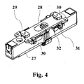
- the invention according to one embodiment comprises a sealed and tamper-proof housing 27 for storing batteries and / or batteries.
- the housing 27 is secured to a fixed support such as rail or wall via mounting plate 28 shaped to fit into the opening of a rail with fastening means 29 in said rail.
- These means 29 are threaded nuts forming a buttonhole with the light of the rail. The tightening in the direction of tightening rotates these nuts in the guide rail in which the nuts lock to complete the screwing and tightening of the sole 28, complementary fixing means 30 allow the attachment of the sole on flat surfaces.
- the sole 28 is secured to the housing 27 by means of the pulls 31 coupling and clamping lips 32 integral with the side walls of the housing and the sides of the sole.
- Said housing 27 contains batteries connected to a terminal block receiving the batteries of the battery power supply by the sector and / or by solar panels.
- the housing 27 is connected to the housing 1 by a connecting wire 6 crimped into the housing 27 and having a connection connector with polarizing means with the housing 1.
- the housing may contain a daughter card receiving the zones 12 and / or 13 and / or 14.
- the design of the housing 27 allows its location in a carrier rail to the right of the opening where it remains visible and / or audible and accessible. Visible and / or audible to note a malfunction and accessible to initialize the system of automated sliding shutters, to change the block or the batteries if necessary.
- the compactness of this stand-alone power supply unit makes it possible to hide it under rail covers and does not interfere with the movement of the mounts and rollers of the sliding shutters in the carrier rail.
- the charge of the batteries is called floating, ie permanent and relayed by solar panels.
- the invention makes it possible, in view of the design of the housing and its potential location on the carrier rail in the middle of the length and at least the length of the travel, to add a device 33 for retaining and guiding the drive belts. movement of the pulley 34 to the roller mounts of the sliding shutters.
- the device 33 prevents these belts from hanging and becoming visible below the lower level of the hood of the carrier rail.
- the means 33 are clipped on both sides of the lateral walls of the casing 27 by means of folded wings with which the corresponding means of the device 33 are slid.
- the grouping box 1 comprises a complementary tamper-resistant waterproof housing 27 of emergency energy which has fastening means 28, 29 on the rail or on the wall to keep visible and audible the alarm means of emitting diodes. LED light or noisemaker and still to be accessible with the initialization button 14 of the installed system, said housing housing a daughter card 12, 13, 14 comprising the means of alarm, initialization, connection, power supply and connection 6 with the motherboard 10 and the solar panels and incidentally means 33 for retaining and guiding the belt, said means 33 being integral with the walls of the housing 27 of the batteries and removable.
- the invention has a grouping box 1, which offers in addition to the various control services to choose from, automation or prevention of emergency and burglar-proof, a real autonomy in backup power (battery) and autonomous with the use of solar panels.
- the whole is compact able to be housed in a rail and / or under the trim headband hood and associable with other elements of the engine such as motor 2 and / or gear 26, without harming the bulk to achieve a compact set.
- a grouping box 1 according to the invention according to any one of the preceding embodiments related to a motor 2 and a gearbox 26 for the automation and control of an actuating system. a sliding shutter.
Landscapes
- Engineering & Computer Science (AREA)
- Power Engineering (AREA)
- Microelectronics & Electronic Packaging (AREA)
- Charge And Discharge Circuits For Batteries Or The Like (AREA)
- Operating, Guiding And Securing Of Roll- Type Closing Members (AREA)
- Pharmaceuticals Containing Other Organic And Inorganic Compounds (AREA)
- Selective Calling Equipment (AREA)
- Insertion, Bundling And Securing Of Wires For Electric Apparatuses (AREA)
- Casings For Electric Apparatus (AREA)
- Transition And Organic Metals Composition Catalysts For Addition Polymerization (AREA)
- Vehicle Interior And Exterior Ornaments, Soundproofing, And Insulation (AREA)
- Financial Or Insurance-Related Operations Such As Payment And Settlement (AREA)
- Materials For Medical Uses (AREA)
Claims (5)
- Gruppiergehäuse (1) bei elektrischen Vorrichtungen zumindest zur Stromversorgung eines Motors (2) zur Betätigung von mindestens einem Schiebepaneel, welches mindestens ein innen liegendes Klemmenbrett (3) für den Anschluss, Zuleitungsdrähte (5, 6, 8) und ein Antennenglied (7) aufweist, wobei die Zuleitungsdrähte (5, 6, 8) und das Antennenglied mit dem innen liegenden Klemmenbrett (3) für den Anschluss verbunden sind, ferner mindestens einen Schalter zum Öffnen und Schließen des Stromversorgungskreises für den Motor, mindestens einen Transformator (4), um den Motor (2) über einen der Zuleitungsdrähte (8) mit einer Niederspannung zu versorgen, und außerdem eine Weiterschaltvorrichtung in Form eines Schrittschalters (23) aus Ferrit mit 16 Polen, einen Trägerflansch (24) zur Aufnahme des Schrittschalters (23), der so ausgebildet ist, dass er einen Sitz zur indexierte Positionierung bildet, und eine Einrichtung zur Befestigung des Gruppiergehäuses (1) an einem Steckergehäuse (26), das mit dem Motor (2) verbindbar ist, und zwei Schalen (1a, 1b), die dicht und unverletzlich verschließbar sind und das Gehäuse der gesamten elektrischen und/oder elektronischen Vorrichtung bilden, wobei sie die Zuleitungsdrähte (5, 6, 8) und das Antennenglied (7) durch Crimpen oder Falzen verschließen, wobei das Gehäuse an dem innen liegenden Klemmenbrett (3) für den Anschluss angeschlossen und fest mit einem unverletzlichen einzigen Sockel (10) verbunden ist, wobei der Sockel (10) so ausgelegt ist, dass er einen Träger für jede elektrische und/oder elektronische Vorrichtung bildet und einteilig mit den Innenwandungen der Schalen des Gehäuses (1a, 1b) verbunden ist, sobald diese geschlossen sind, um so eine einzige unabhängige Baugruppe zu bilden, die Teil einer Baugruppe für den motorischen Antrieb ist.
- Gehäuse (1) nach Anspruch 1, welches zumindest die folgenden Bauteile aufweist:- eine Hauptplatine (10), welche alle Funktionsbereiche (11) aufweist, die programmierbar oder nicht programmierbar sind, sowie die entsprechenden elektrischen und/oder elektronischen und auch mechanischen Vorrichtungen umfasst;- für jede elektrische und/oder elektronische und/oder mechanische Vorrichtung einen Funktionsbereich (11) zum Zwecke des Empfangs, der Speicherung, der Verarbeitung, der Aussendung, der Steuerung von digitalisierten Daten zur Steuerung und Vorsteuerung der gegebenenfalls zugeordneten Vorrichtungen;- einen Versorgungsbereich (12) für die Notstromversorgung des Motors (2);- einen Bereich (15) zur Stromversorgung des Motors (2) und der Batterien aus dem öffentlichen Stromnetz und zur Umwandlung desselben in eine Gleichstromspannung von 6 Volt;- einen Bereich (16) zur Vorsteuerung des Motors (2), der Sicherheitseinrichtungen, der Betriebsparameter und jedes anderen Parameters;- einen Bereich (19) zur Fernsteuerung mit einer Schnittstelle zum Senden und Empfangen von Funkwellen, WIFI, infrarotwellen und Telefonsignalen;- einen CPU-Bereich (20) mit einem Prozessor zur Vorsteuerung und zentralisierten Lenkung des Betriebs der Funktionsbereiche (11);- einen Bereich (21), welcher Vorrichtungen zur Schrittschaltung mit einem Halleffektsensor (22) und einem Ferrit-Schrittschalter (23) mit 16 Polen einerseits und der Schnittstelle zur Erfassung und Verarbeitung der vom Sensor (23) erzeugten Impulse aufweist;- wobei die Bereiche 11 so ausgelegt sind, dass sie allein oder in Verbindung mit der Hauptplatine auf Tochterkarten verlagerbar sind, welche unter anderem in dem Gehäuse zur Notromversorgung exportiert werden können.
- Gehäuse (1) nach Anspruch 1, welches zumindest die folgenden Bauteile aufweist,- eine Hauptplatine (10), welche alle Funktionsbereiche (11) aufweist, die programmierbar oder nicht programmierbar sind, sowie die entsprechenden elektrischen und/oder elektronischen und auch mechanischen Vorrichtungen umfasst;- für jede elektrische und/oder elektronische und/oder mechanische Vorrichtung einen Funktionsbereich (11) zum Zwecke des Empfangs, der Speicherung, der Verarbeitung, der Aussendung, der Steuerung von digitalisierten Daten zur Steuerung und Vorsteuerung der gegebenenfalls zugeordneten Vorrichtungen;- einen Versorgungsbereich (12) für die Notstromversorgung des Motors (2);- einen Kontrollbereich (13) zum Kontrollieren des Batteriezustands und der Vorsteuerung der Batteriesicherheit;- einen Bereich (14) zur Verhinderung von Betriebsstörungen durch eine als LED bezeichnete Lichtsendeeinrichtung bzw einen Rasselsender und zur Steuerung der Initialisierung mittels einer Schaltfläche und eines Temperaturfühlers,- einen Bereich (15) zur Stromversorgung des Motors (2) und der Batterien aus dem öffentlichen Stromnetz und zur Umwandlung des Stroms in eine Gleichstromspannung von 6 Volt;- einen Bereich (16) zur Vorsteuerung des Motors (2), der Sicherheitseinrichtungen, der Betriebsparameter und jedes anderen Parameters;- einen Bereich (17) zur Kontrolle des Motorzustands;- einen Bereich (18) zur Steuerung der Drahtleitungen,- einen Bereich (19) zur Fernsteuerung mit einer Schnittstelle zum Senden und Empfangen von Funkwellen, WIFI, Infrarotwellen und Telefonsignalen;- einen CPU-Bereich (20) mit einem Prozessor zur Vorsteuerung und zentralisierten Lenkung des Betriebs der Funktionsbereiche (11):- einen Bereich (21), welcher Vorrichtungen zur Schrittschaltung mit einem Halleffektsensor (22) und einem Ferrit-Schrittschalter (23) mit (16) Polen einerseits und der Schnittstelle zur Erfassung und Verarbeitung der vom Sensor (23) erzeugten Impulse aufweist;- wobei die Bereiche 11 so ausgelegt sind, dass sie allein oder in Verbindung mit der Hauptplatine auf Tochterkarten verlagerbar sind, welche unter anderem in dem Gehäuse zur Notromversorgung exportiert werden können.
- Gehäuse nach einem der vorhergehenden Ansprüche, welches ein zusätzliches unverletzliches dichtes Gehäuse (27) für den Notstrom aufweist, welches mit Einrichtungen zur Befestigung (28, 29) auf der Schiene oder an der Wand ausgerüstet ist, um die Alarmeinrichtungen mit Lichtsendedioden bzw so genannte LEDs oder eines Rasselsenders sichtbar und hörbar zu halten und auch um mit dem Knopf zur Initialisierung des eingebauten Systems zugänglich zu sein, wobei in dem Gehäuse eine Tochterkarte (12, 13, 14) aufgenommen ist, welche Alarmeinrichtungen und Einrichtungen zur Initialisierung, zur Verbindung, zur Stromversorgung und für die Verbindung (6) mit der Hauptplatine (10) und den Solarplatten und ergänzend die Einrichtungen (33) zum Halten und Führen des Riemens aufweist, wobei die Einrichtungen (33) fest mit den Wandungen des Gehäuses (27) mit den Batterien verbunden und abnehmbar sind.
- Verwendung eines erfindungsgemäßen Gruppiergehäuses (1) nach einem der vorhergehenden Ansprüche, das zur Automatisierung und Regelung eines Systems zur Betätigung eines Schiebepaneels mit einem Motor (2) und einem Untersetzungsgetriebe (26) verbunden ist.
Priority Applications (1)
| Application Number | Priority Date | Filing Date | Title |
|---|---|---|---|
| PL07360043T PL1912309T3 (pl) | 2006-10-13 | 2007-10-05 | Obudowa grupująca i jej zastosowanie |
Applications Claiming Priority (1)
| Application Number | Priority Date | Filing Date | Title |
|---|---|---|---|
| FR0609010A FR2907308B1 (fr) | 2006-10-13 | 2006-10-13 | Boitier de regroupement et son utilisation |
Publications (2)
| Publication Number | Publication Date |
|---|---|
| EP1912309A1 EP1912309A1 (de) | 2008-04-16 |
| EP1912309B1 true EP1912309B1 (de) | 2011-03-09 |
Family
ID=37946391
Family Applications (1)
| Application Number | Title | Priority Date | Filing Date |
|---|---|---|---|
| EP07360043A Active EP1912309B1 (de) | 2006-10-13 | 2007-10-05 | Gruppiergehäuse und derartige Verwendung |
Country Status (7)
| Country | Link |
|---|---|
| EP (1) | EP1912309B1 (de) |
| AT (1) | ATE501544T1 (de) |
| DE (1) | DE602007012979D1 (de) |
| DK (1) | DK1912309T3 (de) |
| ES (1) | ES2362441T3 (de) |
| FR (1) | FR2907308B1 (de) |
| PL (1) | PL1912309T3 (de) |
Families Citing this family (2)
| Publication number | Priority date | Publication date | Assignee | Title |
|---|---|---|---|---|
| CN105676701B (zh) * | 2016-03-06 | 2018-11-09 | 江苏盛德电子仪表有限公司 | 一种易安装的智能仪表 |
| WO2019116131A1 (en) * | 2017-12-11 | 2019-06-20 | Mini Motor - S.R.L. | Electric actuator with wireless data exchange module |
Family Cites Families (4)
| Publication number | Priority date | Publication date | Assignee | Title |
|---|---|---|---|---|
| JPH0712637Y2 (ja) * | 1988-02-12 | 1995-03-29 | ワイケイケイ株式会社 | 電動遮閉装置の太陽電池パネル取付装置 |
| US6497267B1 (en) * | 2000-04-07 | 2002-12-24 | Lutron Electronics Co., Inc. | Motorized window shade with ultraquiet motor drive and ESD protection |
| JP2003138871A (ja) * | 2001-10-30 | 2003-05-14 | Bunka Shutter Co Ltd | 閉鎖装置 |
| DE20201325U1 (de) * | 2002-01-16 | 2003-05-28 | Rademacher Geräte-Elektronik GmbH & Co. KG, 46414 Rhede | Elektronisches Steuergerät |
-
2006
- 2006-10-13 FR FR0609010A patent/FR2907308B1/fr not_active Expired - Fee Related
-
2007
- 2007-10-05 EP EP07360043A patent/EP1912309B1/de active Active
- 2007-10-05 AT AT07360043T patent/ATE501544T1/de active
- 2007-10-05 DK DK07360043.9T patent/DK1912309T3/da active
- 2007-10-05 DE DE602007012979T patent/DE602007012979D1/de active Active
- 2007-10-05 ES ES07360043T patent/ES2362441T3/es active Active
- 2007-10-05 PL PL07360043T patent/PL1912309T3/pl unknown
Also Published As
| Publication number | Publication date |
|---|---|
| FR2907308B1 (fr) | 2009-01-16 |
| ES2362441T3 (es) | 2011-07-05 |
| DK1912309T3 (da) | 2011-06-27 |
| FR2907308A1 (fr) | 2008-04-18 |
| ATE501544T1 (de) | 2011-03-15 |
| DE602007012979D1 (de) | 2011-04-21 |
| PL1912309T3 (pl) | 2011-12-30 |
| EP1912309A1 (de) | 2008-04-16 |
Similar Documents
| Publication | Publication Date | Title |
|---|---|---|
| EP0351272B1 (de) | Mit modularem Verbindungsmittel ausgestatteter elektrischer Motor | |
| EP2567055B1 (de) | Verfahren zur steuerung der versorgung von elektrischem strom von einer batterie einer okklusionsvorrichtung durch ein photovoltaikmodul und okklusionsvorrichtung mit einem system für solch eine steuerung | |
| FR2772203A1 (fr) | Dispositif d'interruption electrique comportant un module de communication | |
| EP1912309B1 (de) | Gruppiergehäuse und derartige Verwendung | |
| WO2022002955A1 (fr) | Dispositif d'occultation comprenant un dispositif d'entraînement motorisé | |
| FR3154432A1 (fr) | Procédé de commande d’un dispositif d’occultation et dispositif d’occultation associé | |
| FR3055349A1 (fr) | Dispositif d'entrainement motorise pour une installation domotique de fermeture ou de protection solaire et installation domotique associee | |
| FR2842860A1 (fr) | Bloc d'alimentation pour volets roulants et similaires a commande motorisee | |
| FR2872537A1 (fr) | Dispositif de commande automatisee d'ouverture et de fermeture de portail ou fenetre a double battant | |
| EP4008876A1 (de) | Elektromechanisches stellglied und verschluss-, verdunkelungs- oder sonnenschutzanlage, die ein solches stellglied umfasst | |
| EP1710389B1 (de) | Motorantriebsvorrichtung, insbesondere für eine motorisierten Verschlusseinrichtung | |
| EP3420784A1 (de) | System zur steuerung der stromversorgung eines energizers für elektrozaun und verfahren zum betrieb solch eines systems | |
| EP0065535B1 (de) | Überwachungsgerät | |
| FR2883913A1 (fr) | Dispositif d'entrainement a moteur tubulaire, notamment pour systeme de fermeture motorise | |
| EP0911709A2 (de) | Haushaltssystem zur intelligenten Steuerung des Wohnbereichs | |
| EP1172516B1 (de) | Steuervorrichtung für Rolladen | |
| EP4206435A1 (de) | Stromversorgungsvorrichtung für ein elektrisches ladesystem | |
| EP1587148A1 (de) | Photovoltaisches Modul und dieses anwendendes photovoltaisches System zur Stromerzeugung | |
| EP4307520B1 (de) | Aktuator für den antrieb eines bildschirms mit externer stromversorgung | |
| FR2767853A1 (fr) | Ensemble de cles et de serrures et applications a des antivols urbains pour cycles | |
| EP4047170B1 (de) | Elektromechanisches stellglied, motorbetriebene antriebsvorrichtung mit einem solchen elektromechanischen stellglied und verdunkelungsvorrichtung mit einer solchen motorbetriebenen antriebsvorrichtung | |
| EP0731001A1 (de) | Stromversorgungseinrichtung für Wohnwagen oder dergleichen | |
| EP2243915B1 (de) | Motorisierungssystem für Öffnungselemente, und entsprechende Anwendung | |
| WO2025083137A1 (fr) | Dispositif d'occultation et procédé de commande d'un tel dispositif d'occultation | |
| BE1023588B1 (fr) | Porte formee d'un bati et d'un vantail dote d'un dispositif d'eclairage |
Legal Events
| Date | Code | Title | Description |
|---|---|---|---|
| PUAI | Public reference made under article 153(3) epc to a published international application that has entered the european phase |
Free format text: ORIGINAL CODE: 0009012 |
|
| AK | Designated contracting states |
Kind code of ref document: A1 Designated state(s): AT BE BG CH CY CZ DE DK EE ES FI FR GB GR HU IE IS IT LI LT LU LV MC MT NL PL PT RO SE SI SK TR |
|
| AX | Request for extension of the european patent |
Extension state: AL BA HR MK RS |
|
| 17P | Request for examination filed |
Effective date: 20080602 |
|
| AKX | Designation fees paid |
Designated state(s): AT BE BG CH CY CZ DE DK EE ES FI FR GB GR HU IE IS IT LI LT LU LV MC MT NL PL PT RO SE SI SK TR |
|
| 17Q | First examination report despatched |
Effective date: 20090423 |
|
| GRAP | Despatch of communication of intention to grant a patent |
Free format text: ORIGINAL CODE: EPIDOSNIGR1 |
|
| GRAS | Grant fee paid |
Free format text: ORIGINAL CODE: EPIDOSNIGR3 |
|
| GRAA | (expected) grant |
Free format text: ORIGINAL CODE: 0009210 |
|
| AK | Designated contracting states |
Kind code of ref document: B1 Designated state(s): AT BE BG CH CY CZ DE DK EE ES FI FR GB GR HU IE IS IT LI LT LU LV MC MT NL PL PT RO SE SI SK TR |
|
| REG | Reference to a national code |
Ref country code: GB Ref legal event code: FG4D Free format text: NOT ENGLISH |
|
| REG | Reference to a national code |
Ref country code: CH Ref legal event code: EP |
|
| REG | Reference to a national code |
Ref country code: IE Ref legal event code: FG4D Free format text: LANGUAGE OF EP DOCUMENT: FRENCH |
|
| REF | Corresponds to: |
Ref document number: 602007012979 Country of ref document: DE Date of ref document: 20110421 Kind code of ref document: P |
|
| REG | Reference to a national code |
Ref country code: DE Ref legal event code: R096 Ref document number: 602007012979 Country of ref document: DE Effective date: 20110421 |
|
| REG | Reference to a national code |
Ref country code: RO Ref legal event code: EPE |
|
| REG | Reference to a national code |
Ref country code: SE Ref legal event code: TRGR |
|
| REG | Reference to a national code |
Ref country code: DK Ref legal event code: T3 |
|
| REG | Reference to a national code |
Ref country code: ES Ref legal event code: FG2A Ref document number: 2362441 Country of ref document: ES Kind code of ref document: T3 Effective date: 20110705 |
|
| REG | Reference to a national code |
Ref country code: NL Ref legal event code: VDEP Effective date: 20110309 |
|
| PG25 | Lapsed in a contracting state [announced via postgrant information from national office to epo] |
Ref country code: LV Free format text: LAPSE BECAUSE OF FAILURE TO SUBMIT A TRANSLATION OF THE DESCRIPTION OR TO PAY THE FEE WITHIN THE PRESCRIBED TIME-LIMIT Effective date: 20110309 Ref country code: LT Free format text: LAPSE BECAUSE OF FAILURE TO SUBMIT A TRANSLATION OF THE DESCRIPTION OR TO PAY THE FEE WITHIN THE PRESCRIBED TIME-LIMIT Effective date: 20110309 |
|
| LTIE | Lt: invalidation of european patent or patent extension |
Effective date: 20110309 |
|
| REG | Reference to a national code |
Ref country code: GR Ref legal event code: EP Ref document number: 20110401433 Country of ref document: GR Effective date: 20110714 |
|
| PG25 | Lapsed in a contracting state [announced via postgrant information from national office to epo] |
Ref country code: SI Free format text: LAPSE BECAUSE OF FAILURE TO SUBMIT A TRANSLATION OF THE DESCRIPTION OR TO PAY THE FEE WITHIN THE PRESCRIBED TIME-LIMIT Effective date: 20110309 Ref country code: CY Free format text: LAPSE BECAUSE OF FAILURE TO SUBMIT A TRANSLATION OF THE DESCRIPTION OR TO PAY THE FEE WITHIN THE PRESCRIBED TIME-LIMIT Effective date: 20110309 Ref country code: BG Free format text: LAPSE BECAUSE OF FAILURE TO SUBMIT A TRANSLATION OF THE DESCRIPTION OR TO PAY THE FEE WITHIN THE PRESCRIBED TIME-LIMIT Effective date: 20110609 Ref country code: FI Free format text: LAPSE BECAUSE OF FAILURE TO SUBMIT A TRANSLATION OF THE DESCRIPTION OR TO PAY THE FEE WITHIN THE PRESCRIBED TIME-LIMIT Effective date: 20110309 |
|
| REG | Reference to a national code |
Ref country code: IE Ref legal event code: FD4D |
|
| REG | Reference to a national code |
Ref country code: HU Ref legal event code: AG4A Ref document number: E011370 Country of ref document: HU |
|
| PG25 | Lapsed in a contracting state [announced via postgrant information from national office to epo] |
Ref country code: EE Free format text: LAPSE BECAUSE OF FAILURE TO SUBMIT A TRANSLATION OF THE DESCRIPTION OR TO PAY THE FEE WITHIN THE PRESCRIBED TIME-LIMIT Effective date: 20110309 Ref country code: PT Free format text: LAPSE BECAUSE OF FAILURE TO SUBMIT A TRANSLATION OF THE DESCRIPTION OR TO PAY THE FEE WITHIN THE PRESCRIBED TIME-LIMIT Effective date: 20110711 Ref country code: IE Free format text: LAPSE BECAUSE OF FAILURE TO SUBMIT A TRANSLATION OF THE DESCRIPTION OR TO PAY THE FEE WITHIN THE PRESCRIBED TIME-LIMIT Effective date: 20110309 |
|
| PG25 | Lapsed in a contracting state [announced via postgrant information from national office to epo] |
Ref country code: IS Free format text: LAPSE BECAUSE OF FAILURE TO SUBMIT A TRANSLATION OF THE DESCRIPTION OR TO PAY THE FEE WITHIN THE PRESCRIBED TIME-LIMIT Effective date: 20110709 |
|
| PG25 | Lapsed in a contracting state [announced via postgrant information from national office to epo] |
Ref country code: NL Free format text: LAPSE BECAUSE OF FAILURE TO SUBMIT A TRANSLATION OF THE DESCRIPTION OR TO PAY THE FEE WITHIN THE PRESCRIBED TIME-LIMIT Effective date: 20110309 |
|
| REG | Reference to a national code |
Ref country code: PL Ref legal event code: T3 |
|
| PLBE | No opposition filed within time limit |
Free format text: ORIGINAL CODE: 0009261 |
|
| STAA | Information on the status of an ep patent application or granted ep patent |
Free format text: STATUS: NO OPPOSITION FILED WITHIN TIME LIMIT |
|
| 26N | No opposition filed |
Effective date: 20111212 |
|
| REG | Reference to a national code |
Ref country code: DE Ref legal event code: R097 Ref document number: 602007012979 Country of ref document: DE Effective date: 20111212 |
|
| BERE | Be: lapsed |
Owner name: MANTION S.A. Effective date: 20111031 |
|
| PG25 | Lapsed in a contracting state [announced via postgrant information from national office to epo] |
Ref country code: MC Free format text: LAPSE BECAUSE OF NON-PAYMENT OF DUE FEES Effective date: 20111031 |
|
| REG | Reference to a national code |
Ref country code: NL Ref legal event code: RD1H Effective date: 20120611 |
|
| PG25 | Lapsed in a contracting state [announced via postgrant information from national office to epo] |
Ref country code: BE Free format text: LAPSE BECAUSE OF NON-PAYMENT OF DUE FEES Effective date: 20111031 |
|
| BERR | Be: reestablished |
Owner name: MANTION S.A. Effective date: 20120917 |
|
| PGRI | Patent reinstated in contracting state [announced from national office to epo] |
Ref country code: BE Effective date: 20120917 |
|
| PG25 | Lapsed in a contracting state [announced via postgrant information from national office to epo] |
Ref country code: MT Free format text: LAPSE BECAUSE OF FAILURE TO SUBMIT A TRANSLATION OF THE DESCRIPTION OR TO PAY THE FEE WITHIN THE PRESCRIBED TIME-LIMIT Effective date: 20110309 |
|
| REG | Reference to a national code |
Ref country code: NL Ref legal event code: RD2H Effective date: 20130417 |
|
| PG25 | Lapsed in a contracting state [announced via postgrant information from national office to epo] |
Ref country code: LU Free format text: LAPSE BECAUSE OF NON-PAYMENT OF DUE FEES Effective date: 20111005 |
|
| PG25 | Lapsed in a contracting state [announced via postgrant information from national office to epo] |
Ref country code: TR Free format text: LAPSE BECAUSE OF FAILURE TO SUBMIT A TRANSLATION OF THE DESCRIPTION OR TO PAY THE FEE WITHIN THE PRESCRIBED TIME-LIMIT Effective date: 20110309 |
|
| PGFP | Annual fee paid to national office [announced via postgrant information from national office to epo] |
Ref country code: GB Payment date: 20151027 Year of fee payment: 9 |
|
| REG | Reference to a national code |
Ref country code: FR Ref legal event code: PLFP Year of fee payment: 10 |
|
| GBPC | Gb: european patent ceased through non-payment of renewal fee |
Effective date: 20161005 |
|
| PG25 | Lapsed in a contracting state [announced via postgrant information from national office to epo] |
Ref country code: GB Free format text: LAPSE BECAUSE OF NON-PAYMENT OF DUE FEES Effective date: 20161005 |
|
| REG | Reference to a national code |
Ref country code: FR Ref legal event code: PLFP Year of fee payment: 11 |
|
| REG | Reference to a national code |
Ref country code: FR Ref legal event code: PLFP Year of fee payment: 12 |
|
| PGFP | Annual fee paid to national office [announced via postgrant information from national office to epo] |
Ref country code: RO Payment date: 20191007 Year of fee payment: 13 |
|
| PGFP | Annual fee paid to national office [announced via postgrant information from national office to epo] |
Ref country code: SK Payment date: 20200910 Year of fee payment: 14 Ref country code: CZ Payment date: 20200910 Year of fee payment: 14 |
|
| PGFP | Annual fee paid to national office [announced via postgrant information from national office to epo] |
Ref country code: ES Payment date: 20201209 Year of fee payment: 14 Ref country code: DE Payment date: 20201027 Year of fee payment: 14 Ref country code: IT Payment date: 20201019 Year of fee payment: 14 Ref country code: FR Payment date: 20201003 Year of fee payment: 14 Ref country code: DK Payment date: 20201029 Year of fee payment: 14 Ref country code: GR Payment date: 20201029 Year of fee payment: 14 Ref country code: HU Payment date: 20201201 Year of fee payment: 14 Ref country code: SE Payment date: 20201028 Year of fee payment: 14 Ref country code: AT Payment date: 20201027 Year of fee payment: 14 Ref country code: CH Payment date: 20201023 Year of fee payment: 14 |
|
| PGFP | Annual fee paid to national office [announced via postgrant information from national office to epo] |
Ref country code: PL Payment date: 20201002 Year of fee payment: 14 Ref country code: BE Payment date: 20201020 Year of fee payment: 14 |
|
| PG25 | Lapsed in a contracting state [announced via postgrant information from national office to epo] |
Ref country code: RO Free format text: LAPSE BECAUSE OF NON-PAYMENT OF DUE FEES Effective date: 20201005 |
|
| REG | Reference to a national code |
Ref country code: DE Ref legal event code: R119 Ref document number: 602007012979 Country of ref document: DE |
|
| REG | Reference to a national code |
Ref country code: DK Ref legal event code: EBP Effective date: 20211031 |
|
| REG | Reference to a national code |
Ref country code: CH Ref legal event code: PL Ref country code: SE Ref legal event code: EUG |
|
| PG25 | Lapsed in a contracting state [announced via postgrant information from national office to epo] |
Ref country code: CZ Free format text: LAPSE BECAUSE OF NON-PAYMENT OF DUE FEES Effective date: 20211005 |
|
| REG | Reference to a national code |
Ref country code: SK Ref legal event code: MM4A Ref document number: E 9452 Country of ref document: SK Effective date: 20211005 Ref country code: AT Ref legal event code: MM01 Ref document number: 501544 Country of ref document: AT Kind code of ref document: T Effective date: 20211005 |
|
| REG | Reference to a national code |
Ref country code: BE Ref legal event code: MM Effective date: 20211031 |
|
| PG25 | Lapsed in a contracting state [announced via postgrant information from national office to epo] |
Ref country code: SK Free format text: LAPSE BECAUSE OF NON-PAYMENT OF DUE FEES Effective date: 20211005 Ref country code: SE Free format text: LAPSE BECAUSE OF NON-PAYMENT OF DUE FEES Effective date: 20211006 Ref country code: HU Free format text: LAPSE BECAUSE OF NON-PAYMENT OF DUE FEES Effective date: 20211006 Ref country code: DE Free format text: LAPSE BECAUSE OF NON-PAYMENT OF DUE FEES Effective date: 20220503 Ref country code: BE Free format text: LAPSE BECAUSE OF NON-PAYMENT OF DUE FEES Effective date: 20211031 |
|
| PG25 | Lapsed in a contracting state [announced via postgrant information from national office to epo] |
Ref country code: LI Free format text: LAPSE BECAUSE OF NON-PAYMENT OF DUE FEES Effective date: 20211031 Ref country code: GR Free format text: LAPSE BECAUSE OF NON-PAYMENT OF DUE FEES Effective date: 20220506 Ref country code: CH Free format text: LAPSE BECAUSE OF NON-PAYMENT OF DUE FEES Effective date: 20211031 Ref country code: AT Free format text: LAPSE BECAUSE OF NON-PAYMENT OF DUE FEES Effective date: 20211005 |
|
| PG25 | Lapsed in a contracting state [announced via postgrant information from national office to epo] |
Ref country code: FR Free format text: LAPSE BECAUSE OF NON-PAYMENT OF DUE FEES Effective date: 20211031 |
|
| PG25 | Lapsed in a contracting state [announced via postgrant information from national office to epo] |
Ref country code: IT Free format text: LAPSE BECAUSE OF NON-PAYMENT OF DUE FEES Effective date: 20211005 Ref country code: DK Free format text: LAPSE BECAUSE OF NON-PAYMENT OF DUE FEES Effective date: 20211031 |
|
| REG | Reference to a national code |
Ref country code: ES Ref legal event code: FD2A Effective date: 20230202 |
|
| PG25 | Lapsed in a contracting state [announced via postgrant information from national office to epo] |
Ref country code: ES Free format text: LAPSE BECAUSE OF NON-PAYMENT OF DUE FEES Effective date: 20211006 |
|
| PG25 | Lapsed in a contracting state [announced via postgrant information from national office to epo] |
Ref country code: PL Free format text: LAPSE BECAUSE OF NON-PAYMENT OF DUE FEES Effective date: 20211005 |