EP1912357A2 - Effiziente Rahmenstruktur für die digitale Satellitenkommunikation - Google Patents
Effiziente Rahmenstruktur für die digitale Satellitenkommunikation Download PDFInfo
- Publication number
- EP1912357A2 EP1912357A2 EP07016669A EP07016669A EP1912357A2 EP 1912357 A2 EP1912357 A2 EP 1912357A2 EP 07016669 A EP07016669 A EP 07016669A EP 07016669 A EP07016669 A EP 07016669A EP 1912357 A2 EP1912357 A2 EP 1912357A2
- Authority
- EP
- European Patent Office
- Prior art keywords
- frame
- receiver
- frame format
- modulation
- codewords
- Prior art date
- Legal status (The legal status is an assumption and is not a legal conclusion. Google has not performed a legal analysis and makes no representation as to the accuracy of the status listed.)
- Withdrawn
Links
Images


Classifications
-
- H—ELECTRICITY
- H04—ELECTRIC COMMUNICATION TECHNIQUE
- H04L—TRANSMISSION OF DIGITAL INFORMATION, e.g. TELEGRAPHIC COMMUNICATION
- H04L1/00—Arrangements for detecting or preventing errors in the information received
- H04L1/004—Arrangements for detecting or preventing errors in the information received by using forward error control
- H04L1/0045—Arrangements at the receiver end
-
- H—ELECTRICITY
- H04—ELECTRIC COMMUNICATION TECHNIQUE
- H04B—TRANSMISSION
- H04B7/00—Radio transmission systems, i.e. using radiation field
- H04B7/14—Relay systems
- H04B7/15—Active relay systems
- H04B7/185—Space-based or airborne stations; Stations for satellite systems
- H04B7/18578—Satellite systems for providing broadband data service to individual earth stations
- H04B7/18582—Arrangements for data linking, i.e. for data framing, for error recovery, for multiple access
-
- H—ELECTRICITY
- H04—ELECTRIC COMMUNICATION TECHNIQUE
- H04L—TRANSMISSION OF DIGITAL INFORMATION, e.g. TELEGRAPHIC COMMUNICATION
- H04L1/00—Arrangements for detecting or preventing errors in the information received
- H04L1/004—Arrangements for detecting or preventing errors in the information received by using forward error control
- H04L1/0072—Error control for data other than payload data, e.g. control data
-
- H—ELECTRICITY
- H04—ELECTRIC COMMUNICATION TECHNIQUE
- H04L—TRANSMISSION OF DIGITAL INFORMATION, e.g. TELEGRAPHIC COMMUNICATION
- H04L1/00—Arrangements for detecting or preventing errors in the information received
- H04L1/0078—Avoidance of errors by organising the transmitted data in a format specifically designed to deal with errors, e.g. location
- H04L1/0083—Formatting with frames or packets; Protocol or part of protocol for error control
-
- H—ELECTRICITY
- H04—ELECTRIC COMMUNICATION TECHNIQUE
- H04L—TRANSMISSION OF DIGITAL INFORMATION, e.g. TELEGRAPHIC COMMUNICATION
- H04L27/00—Modulated-carrier systems
- H04L27/26—Systems using multi-frequency codes
- H04L27/2601—Multicarrier modulation systems
- H04L27/2602—Signal structure
-
- H—ELECTRICITY
- H04—ELECTRIC COMMUNICATION TECHNIQUE
- H04L—TRANSMISSION OF DIGITAL INFORMATION, e.g. TELEGRAPHIC COMMUNICATION
- H04L7/00—Arrangements for synchronising receiver with transmitter
- H04L7/04—Speed or phase control by synchronisation signals
- H04L7/08—Speed or phase control by synchronisation signals the synchronisation signals recurring cyclically
-
- H—ELECTRICITY
- H04—ELECTRIC COMMUNICATION TECHNIQUE
- H04L—TRANSMISSION OF DIGITAL INFORMATION, e.g. TELEGRAPHIC COMMUNICATION
- H04L27/00—Modulated-carrier systems
- H04L27/26—Systems using multi-frequency codes
- H04L27/2601—Multicarrier modulation systems
- H04L27/2602—Signal structure
- H04L27/261—Details of reference signals
- H04L27/2613—Structure of the reference signals
-
- H—ELECTRICITY
- H04—ELECTRIC COMMUNICATION TECHNIQUE
- H04L—TRANSMISSION OF DIGITAL INFORMATION, e.g. TELEGRAPHIC COMMUNICATION
- H04L27/00—Modulated-carrier systems
- H04L27/26—Systems using multi-frequency codes
- H04L27/2601—Multicarrier modulation systems
- H04L27/2602—Signal structure
- H04L27/261—Details of reference signals
- H04L27/2613—Structure of the reference signals
- H04L27/26134—Pilot insertion in the transmitter chain, e.g. pilot overlapping with data, insertion in time or frequency domain
-
- H—ELECTRICITY
- H04—ELECTRIC COMMUNICATION TECHNIQUE
- H04L—TRANSMISSION OF DIGITAL INFORMATION, e.g. TELEGRAPHIC COMMUNICATION
- H04L27/00—Modulated-carrier systems
- H04L27/26—Systems using multi-frequency codes
- H04L27/2601—Multicarrier modulation systems
- H04L27/2647—Arrangements specific to the receiver only
- H04L27/2655—Synchronisation arrangements
- H04L27/2656—Frame synchronisation, e.g. packet synchronisation, time division duplex [TDD] switching point detection or subframe synchronisation
-
- H—ELECTRICITY
- H04—ELECTRIC COMMUNICATION TECHNIQUE
- H04L—TRANSMISSION OF DIGITAL INFORMATION, e.g. TELEGRAPHIC COMMUNICATION
- H04L5/00—Arrangements affording multiple use of the transmission path
- H04L5/003—Arrangements for allocating sub-channels of the transmission path
- H04L5/0048—Allocation of pilot signals, i.e. of signals known to the receiver
Definitions
- the invention relates to digital satellite communication and in particular to frame designs for transmitted signals to increase transmission efficiency and FEC performance and to simplify satellite receiver implementation such as synchronization control and FEC decoding.
- a goal is to transport digital data bits representing user information such as video, audio and other data types from a source (or a transmitter) to a destination (or a receiver or even multiple receivers) with a pre-defined maximum transportation error rate or bit error rate (BER).
- BER bit error rate
- typical transmitters usually add redundant bits into an original data bit stream for transmission.
- the process of adding redundant bits is called forward error control (FEC) encoding.
- FEC forward error control
- a receiver it is possible for a receiver to recover original information with an error rate less than the defined error rate by running an FEC decoding algorithm, even if the transmitted bits are contaminated by extraneous signals (e. g. noise and/or interference) and distorted by non-ideal channel characteristics.
- a maximum BER of 10 -2 is acceptable.
- a zero BER is required.
- data is often re-transmitted if a receiver detects any un-correctable errors.
- a BER of less than 10 -9 is preferred to provide a smooth display of a video signal on video monitors.
- Such a BER is often referred to as a Quasi-Error-Free (QEF) condition.
- QEF Quasi-Error-Free
- Frame formatting design is critical to overall system performance and can directly impact the cost of establishing and operating a communication system. Frame formatting design often depends on many factors, such as channel characteristics, modulation type and FEC scheme. A well-designed frame format may result in high performance receivers that achieve fast frame acquisition, reliable tracking (time and frequency lock) and improved FEC decoding performance (such as meeting the required BER) with minimum overhead at a low cost.
- a unique approach to frame satellite transmission messages to achieve excellent communication performance with simple receiver implementation is presented.
- messages in bits are grouped into many consecutive signal blocks called frames after the encoding.
- Each frame typically includes a frame header and a synchronization waveform to allow receivers to synchronize with incoming signal frames, process the headers, and decode the messages if indicated by the header information.
- a frame typically carries a fixed number of information bits, which are in turn encoded into one codeword. This is acceptable if the systems only employ modulations with a fixed dimension, e. g.
- frame formats are designed to allow multiple LDPC (or other FEC) codewords in a single frame for a highly efficient transmission.
- each codeword may have a different modulation dimension and/or code rate.
- a synchronization waveform called unique word (UW)
- UW unique word
- ACC auxiliary control code
- frame header is attached to the beginning of each frame.
- the receiver knows where to look for the UW, ACC and the header, making synchronisation (sync) control extremely simple.
- the sync performance is also ensured due to the evenly distributed UWs.
- the UW is carefully designed to yield sufficient synchronization performance under the most adverse satellite channel conditions such as transponder distortion, poor receiver LNA (low-noise amplifier), large frequency and/or timing errors, etc.
- the ACC may employ a simple orthogonal tone code that carries information on modulation and/or code rate.
- the frame header may be designed to carry sufficient information for decoding multiple codewords while keeping a minimal overhead.
- pilot waveforms are inserted uniformly during a frame to further enhance the synchronization performance.
- the size of each pilot segment may be adjustable according to channel condition, thus reducing overhead when channel conditions and modulation and code rate allow for a smaller or zero pilot.
- the frames are scrambled by a random sequence which may be a member of the gold sequence set.
- a frame format of a digital satellite transmission may have: a plurality of frames, each frame having a fixed number of modulated symbols, regardless of a modulation type of the system, and each frame beginning with a unique word; wherein a spacing, in number of symbols, between any two consecutive unique words is identical, regardless of modulation type in the system.
- a plurality of evenly distributed pilot segments are inserted into each frame, the pilot segments being identical for all frames in terms of locations and waveforms, regardless of a modulation type employed.
- a length of the pilot segments is adjustable.
- the number of symbols per frame excluding the unique word, an auxiliary control code and the pilot segments, perfectly accommodates a different number of codewords for each different modulation.
- multiple codewords in each frame share one frame header.
- network operation information and/or other private information may be transmitted through a plurality of Network Bytes in a header of each frame.
- a digital satellite receiver system may process a received signal, comprising: a receiver to receive the signal; and a processor to process the signal, wherein the signal comprises a frame format that contains a fixed number of modulated symbols per frame and a unique word at a beginning of each frame.
- said receiver can process an inserted pilot segment of a given length if in a pilot operation mode.
- said receiver can decode a plurality of FEC codewords in a single frame, regardless of modulation employed.
- said receiver can decode all the codewords in a frame based on only a header embedded in the first codeword of the frame, regardless of number of codewords in the frame.
- said receiver can decode network operation information and/or other private information located immediately following a header field in each frame for any modulation.
- a digital communications system may have: a transmitter to transmit a digital signal; and a receiver to receive the digital signal; wherein the digital signal comprises a plurality of frames, each frame comprising at least one codeword, wherein said system supports at least two different modulations, and wherein each of the plurality of frames has the same number of symbols.
- the plurality of frames have the same fixed physical time for a given transmission rate or symbol rate.
- codewords in the same frame may have different modulations for Adaptive Coding and Modulation (ACM) mode.
- ACM Adaptive Coding and Modulation
- each of the plurality of frames further comprises a Unique Word at a predetermined position.
- the predetermined position is at the beginning of the frame.
- a first codeword in each frame comprises a header, the header comprising a plurality of Network Bytes to transmit network operator information and other private information.
- the header further comprises a PSTART indicator to identify a position at which payload data begins.
- the header further comprises an LBYTE portion to indicate a length of the frame.
- the header further comprises a PBYTE portion to indicate an amount of padding added to the first codeword.
- the header further comprises a PBYTE portion to indicate an amount of padding added to the frame.
- a number of codewords in a frame is determined by the modulation of the frame.
- a method for transmitting a digital signal may involve: transmitting a digital signal; and receiving the digital signal; wherein the digital signal comprises a plurality of frames, each frame comprising at least one codeword, wherein said system supports at least two different modulations, and wherein each of the plurality of frames has the same number of symbols.
- the Unique Words are received at a fixed rate.
- the fixed rate is a predetermined rate.
- a digital communications system may have: a receiver to receive the digital signal; wherein the digital signal comprises a plurality of frames, each frame comprising at least one codeword, wherein said system supports at least two different modulations, and wherein each of the plurality of frames is transmitted in a same amount of time.
- a digital communications system may have: a transmitter to transmit a digital signal;w wherein the digital signal comprises a plurality of frames, each frame comprising at least one codeword, wherein said system supports at least two different modulations, and wherein each of the plurality of frames is transmitted in a same amount of time.
- FIG. 1 illustrates an exemplary block diagram of a satellite transmitter showing a framing process transforming original user data into modulated frames, according to an embodiment of the invention.
- FIG. 2 displays an exemplary formed frame structure, according to an embodiment of the invention.
- FIG. 3 depicts an exemplary encoded data block comprising a number of codewords ready to be formatted to the structure of FIG. 2, according to an embodiment of the invention.
- FIG. 4 depicts an exemplary scrambling sequence generator, according to an embodiment of the invention.
- FIG. 5 depicts an exemplary format of the first codeword in a frame, according to an embodiment of the invention.
- FIG. 6 depicts a second exemplary format of the first codeword in a frame, according to an embodiment of the invention.
- FIG. 7 depicts a third exemplary format of the first codeword in a frame, according to an embodiment of the invention.
- FIG. 8 depicts an exemplary illustration of the Next Frame Composition Table (NFCT) in the first codeword design for ACM application, according to an embodiment of the invention.
- NFCT Next Frame Composition Table
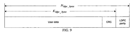
- FIG. 9 depicts an exemplary format of all codewords in an exemplary frame excluding the first codeword, according to an embodiment of the invention.
- a method of formatting a satellite transmission signal provides an efficient signaling structure for satellite receivers to achieve fast acquisition, reliable signal tracking and message decoding with minimal transmission overhead.
- the frame structure serves multiple purposes such as providing the frame time mark for receivers to decode messages, providing a special signal allowing a receiver to acquire the signal when accessing the network and to reduce the time and/or frequency errors such that reliable demodulation and decoding are possible, and providing header information for demodulation and decoding control and user packet striping.
- the special signal may also be used for channel estimation and/or other digital signal processing (DSP) purposes.
- FIG. 1 Illustrated in FIG. 1 is a block diagram of a satellite transmitter showing a framing process to transform original user data into modulated frames, according to various embodiments of the invention.
- the input data bits to be transmitted are first divided into subsequent groups, e. g. group n and group n+1 as shown in FIG. 1.
- Each group contains a number of information bits required for the corresponding frame.
- Each of the information groups is then prefixed by a header (H) by the header insertion module.
- the header, along with each group, is further divided into j (an integer) sub-groups (sg) by the codeword grouping module, with each sub-group carrying an equal number of bits.
- j denotes the number of sub-groups in each group.
- the FEC encoder For each sub-group, the FEC encoder computes the error checking and error correction parity bits (P) of a fixed length based on the sub-group's data pattern and attaches the parity bits to the end of the associated sub-group to form a codeword.
- P error checking and error correction parity bits
- the symbol mapping module maps the bit stream of each codeword into modulation symbols according to the corresponding modulation type in the codeword. Following the symbol mapping, all frames are of an equal length, regardless of modulation used.
- the pilot insertion module may insert a number of pilot waves (p) evenly into the encoded frames as shown in FIG. 1. Also, the UW and ACC insertion module will add a UW followed by an ACC at the beginning of each frame. The symbol scrambler scrambles the symbols of each frame but the UW using a fixed scrambling pattern. Finally all the symbols may be modulated to a radio frequency for transmission through an antenna.
- different satellite transponders may use different modulation and different FEC codes.
- the number of information bits (such as in group n and n+1) is constant for all frames.
- the receiver is designed to process signal with different modulation and FEC. The variation of signal modulation in such a system would create a difficulty for physical layer implementation of the satellite receiver if the frame format is not properly designed.
- this design leads to the presence of multiple codewords in each frame, and thereby offers a higher transmission efficiency for a relatively shorter but powerful FEC codeword due to a smaller overhead, especially for higher dimensions of modulation where more codewords are accommodated in a frame.
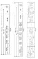
- FIG. 2 depicts an exemplary frame format of a transmitted frame, according to an embodiment of the invention.
- the frame starts with a 64-symbol UW, followed by 64-symbol ACC, and m+1 segments of encoded data (or payload data) separated by m evenly distributed pilots.
- the UW is designed to yield a good detection property to provide a fast acquisition.
- the ACC may employ multi-tone modulation to convey multiple information bits that contain the information on the modulation type and the FEC code rate, which is used for proper demodulation and decoding.
- each row (g 0 through g 7 ) of matrix G is a tone which is orthogonal to other rows.
- the sums represent XOR operation.
- the 128-bit vector B may alternatively be assigned to the I and Q of the QPSK modulator to yield the final 64-symbol ACC waveform.
- the number of payload segments (m+1) between two consecutive pilots segments in each frame is determined by the frame length in symbols and the distance between the two pilot segments, which is designed to provide reliable synchronization with minimal overhead.
- maintaining pilot pattern and location constant for different modulation and FEC decoding is extremely ideal.
- the desired information length between two consecutive pilots is 1280 symbols, regardless of modulation used.
- the size of each pilot wave may also be adjustable. Frames for an extreme case may contain no pilot so as to achieve the smallest overhead. In this case, modulation dimension is usually low and channel is usually fair.
- an integer is assigned to a number of LDPC codewords in each frame as the payload data.
- the benefit is a simple decoder control logic where the decoder does not need to decode payload across the frame boundary.
- N must be divisible by all possible modulation dimensions D.
- the number of symbols in the codeword corresponding to modulation dimension 2, 3, 4 and 5 are 7680, 5120, 3840 and 3072, respectively.
- each frame is assigned a number of payload symbols 30720. Therefore, each frame will carry 4, 6, 8 and 10 codewords corresponding to modulation dimension 2, 3, 4 and 5, respectively. Even for non-constant modulation (such as in ACM mode), 10 other combinations of codeword modulation can be provided, sufficient for an ACM application.
- Table 1 lists possible combinations of codeword modulation. There are 14 possible codeword assignments. For example, combination 5 indicates that a frame can take 3 codewords with modulation dimension 2 and 2 codewords with dimension 4. The order in which the codewords are arranged is arbitrary and flexible enough for a network operator.
- Table 1 provides a very efficient way to utilize the frame resources.
- a user's data may not be continuous, it may not be necessary to follow the format defined in the table. For this reason, some unused symbols may be present towards the end of the frame. Those symbols may be defined as dummy symbols and may be modulated by all-zeros bit pattern.
- N dummy 0 (100% efficiency) if N 1 , N 2 , N 3 and N 4 are one of the listed pattern in Table 1.
- Table 1- Assienment of codewords to each modulation dimension Combination index 1 2 3 4 5 6 7 8 9 10 11 12 13 14 Modulation dimension 2 4 6 8 10 3 2 2 2 1 1 1 3 3 3 3 3 4 2 4 6 2 2 4 4 5 5 5 5 5
- FIG. 4 is an example of frame scrambler which can support frame length up to 30,000 symbols, according to various embodiments of the invention.
- the two 15-bit shift registers are used to generate two maximum length pseudo-random sequences which are the preferred pair for a Gold sequence set.
- One Gold sequence is the sum of the two m-sequences.
- the final scrambling sequence with elements in ⁇ 0, 1, 2, 3 ⁇ is achieved.
- the sequence is then used to rotate the input (I, Q) symbols as defined in Table 2.
- the same scrambling pattern may be used for each new frame.
- a header is only embedded in the first codeword of each frame as shown in FIG. 1.
- the codeword length is usually much larger than the header.
- the sharing of one header embedded in the first codeword by all the codewords of a frame results in a higher efficiency and simpler decoder implementation.
- NBYTES these multiples of 16 bytes may be used to convey important information by network operator and other private information.
- One benefit to convey private information in a physical layer is that users can quickly decode the information without waiting for higher layer message decoding.
- Another benefit is that the private data information does not need to interrupt the continuous data stream such as a transport stream at higher layer.
- the receiver at the physical layer can directly output data stream to the higher layer.
- FBYTEE the 8 bits of FBYTE may be used to carry information such as the operation mode, stream type, user ID, etc.
- PSTART this byte may define the starting position of the first complete user packet relative to the beginning of the user data in the first codeword. PSTART is used because codewords and user packets are generally not aligned.
- LBYTE may be used to define a user packet length. This format may be used for applications in which receivers do not know the user packet length in advance.
- the padding bytes (PBYTES) in FIG. 6 and FIG. 7 may be used to define the number of bytes padded with zeros in the frame if the user data does not completely fill the frame.
- An exemplary exception of PBYTES may be for an ACM mode, where PBYTES might only represent the number of zeros padded into the first codeword.
- a Next Frame Composition Table may be designed for an ACM application in which each codeword may be independent from others in a frame in terms of modulation type and/or FEC code rate.
- the NFCT may be used to define the composition of the frame following the current frame.
- the NFCT following a PBYTES takes the syntax as shown in Table 3. The corresponding bit and byte positions are illustrated in FIG. 7.
- FIG. 8 may be defined in various exemplary embodiments of the invention as follows:
- Codeword_count_in_next_frame this may be a 4-bit field indicating one less than the number of LDPC codewords in next frame.
- the codeword index i may start from 0 to code Codeword_count_in_next_frame ⁇ 0. Accordingly, in this exemplary embodiment, at least one codeword in a frame is always transmitted, i. e. the first codeword of each frame is guaranteed for transmission.
- Modulation 2 bits to indicate the modulation scheme.
- Code_rate 4 bits to indicate the code rate.
- FIG. 9 displays an exemplary codeword format for codewords other than the first one.
- codewords may be completed by appending FEC parity bytes having a CRC error checking field and LDPC error correction field.
- a digital communication system comprising the transmitter of item 1, the receiver of item 2 or both.
Landscapes
- Engineering & Computer Science (AREA)
- Computer Networks & Wireless Communication (AREA)
- Signal Processing (AREA)
- Physics & Mathematics (AREA)
- Astronomy & Astrophysics (AREA)
- Aviation & Aerospace Engineering (AREA)
- General Physics & Mathematics (AREA)
- Synchronisation In Digital Transmission Systems (AREA)
- Time-Division Multiplex Systems (AREA)
- Radio Relay Systems (AREA)
Applications Claiming Priority (1)
| Application Number | Priority Date | Filing Date | Title |
|---|---|---|---|
| PCT/CN2006/002427 WO2008034292A1 (en) | 2006-09-18 | 2006-09-18 | Efficient frame structure for digital satellite communication |
Publications (2)
| Publication Number | Publication Date |
|---|---|
| EP1912357A2 true EP1912357A2 (de) | 2008-04-16 |
| EP1912357A3 EP1912357A3 (de) | 2012-09-19 |
Family
ID=39167344
Family Applications (1)
| Application Number | Title | Priority Date | Filing Date |
|---|---|---|---|
| EP07016669A Withdrawn EP1912357A3 (de) | 2006-09-18 | 2007-08-24 | Effiziente Rahmenstruktur für die digitale Satellitenkommunikation |
Country Status (3)
| Country | Link |
|---|---|
| EP (1) | EP1912357A3 (de) |
| TW (1) | TWI325260B (de) |
| WO (1) | WO2008034292A1 (de) |
Cited By (5)
| Publication number | Priority date | Publication date | Assignee | Title |
|---|---|---|---|---|
| EP2178237A1 (de) * | 2008-10-20 | 2010-04-21 | Thomson Licensing | Verfahren zum Senden und Empfangen von Signalinformationen |
| WO2010069996A1 (en) * | 2008-12-16 | 2010-06-24 | Thomson Licensing | Method and device for transmitting and receiving digital information by use of a fec frame comprising at least to fec frame headers |
| EP2320588A3 (de) * | 2009-11-06 | 2012-04-11 | Deutsches Zentrum für Luft- und Raumfahrt e.V. | Verfahren zur Übertragung von Daten |
| CN107534521A (zh) * | 2015-03-02 | 2018-01-02 | 三星电子株式会社 | 发送器及其缩减方法 |
| US10862510B2 (en) | 2015-03-02 | 2020-12-08 | Samsung Electronics Co., Ltd. | Transmitter and shortening method thereof |
Families Citing this family (3)
| Publication number | Priority date | Publication date | Assignee | Title |
|---|---|---|---|---|
| CN102511154B (zh) * | 2010-05-06 | 2014-12-03 | 华为技术有限公司 | 调制发送方法、装置及通信系统 |
| CN103973398A (zh) * | 2013-01-31 | 2014-08-06 | 中兴通讯股份有限公司 | 数据发送、数据接收方法和装置 |
| EP3425806A1 (de) | 2013-05-07 | 2019-01-09 | Huawei Technologies Co., Ltd. | Codierungs- und decodierungsverfahren und -vorrichtung und system |
Family Cites Families (4)
| Publication number | Priority date | Publication date | Assignee | Title |
|---|---|---|---|---|
| US5872775A (en) * | 1996-10-30 | 1999-02-16 | Qualcomm Incorporated | Method and apparatus for performing rate determination |
| US6404755B1 (en) * | 1996-11-07 | 2002-06-11 | Harris Broadband Wireless Access, Inc. | Multi-level information mapping system and method |
| US6956814B1 (en) * | 2000-02-29 | 2005-10-18 | Worldspace Corporation | Method and apparatus for mobile platform reception and synchronization in direct digital satellite broadcast system |
| CN1413021A (zh) * | 2002-08-27 | 2003-04-23 | 强海胜 | 一种多版本电视节目卫星广播/自动接收编录的传输方法 |
-
2006
- 2006-09-18 WO PCT/CN2006/002427 patent/WO2008034292A1/en not_active Ceased
-
2007
- 2007-03-07 TW TW096107923A patent/TWI325260B/zh not_active IP Right Cessation
- 2007-08-24 EP EP07016669A patent/EP1912357A3/de not_active Withdrawn
Cited By (15)
| Publication number | Priority date | Publication date | Assignee | Title |
|---|---|---|---|---|
| US8677206B2 (en) | 2008-10-20 | 2014-03-18 | Thomson Licensing | Method for transmitting and receiving signalling information |
| EP2178237A1 (de) * | 2008-10-20 | 2010-04-21 | Thomson Licensing | Verfahren zum Senden und Empfangen von Signalinformationen |
| CN102187609A (zh) * | 2008-10-20 | 2011-09-14 | 汤姆逊许可公司 | 收发信令信息的方法 |
| CN102187609B (zh) * | 2008-10-20 | 2015-04-08 | 汤姆逊许可公司 | 收发信令信息的方法 |
| US8566663B2 (en) | 2008-10-20 | 2013-10-22 | Thomson Licensing | Method for transmitting and receiving signalling information |
| US8677207B2 (en) | 2008-10-20 | 2014-03-18 | Thomson Licensing | Method for transmitting and receiving signalling information |
| KR101617907B1 (ko) | 2008-12-16 | 2016-05-03 | 톰슨 라이센싱 | 적어도 2개의 fec 프레임 헤더를 포함하는 fec 프레임을 이용하여 디지털 정보를 송수신하기 위한 방법 및 장치 |
| CN102257754B (zh) * | 2008-12-16 | 2014-01-01 | 汤姆森特许公司 | 数字信息的发送和接收方法及装置 |
| WO2010069996A1 (en) * | 2008-12-16 | 2010-06-24 | Thomson Licensing | Method and device for transmitting and receiving digital information by use of a fec frame comprising at least to fec frame headers |
| EP2320588A3 (de) * | 2009-11-06 | 2012-04-11 | Deutsches Zentrum für Luft- und Raumfahrt e.V. | Verfahren zur Übertragung von Daten |
| CN107534521A (zh) * | 2015-03-02 | 2018-01-02 | 三星电子株式会社 | 发送器及其缩减方法 |
| CN107534521B (zh) * | 2015-03-02 | 2020-11-10 | 三星电子株式会社 | 发送器及其缩减方法 |
| US10862510B2 (en) | 2015-03-02 | 2020-12-08 | Samsung Electronics Co., Ltd. | Transmitter and shortening method thereof |
| US11522561B2 (en) | 2015-03-02 | 2022-12-06 | Samsung Electronics Co., Ltd. | Transmitter and shortening method thereof |
| US12074613B2 (en) | 2015-03-02 | 2024-08-27 | Samsung Electronics Co., Ltd. | Transmitter and shortening method thereof |
Also Published As
| Publication number | Publication date |
|---|---|
| TWI325260B (en) | 2010-05-21 |
| WO2008034292A1 (en) | 2008-03-27 |
| TW200816733A (en) | 2008-04-01 |
| EP1912357A3 (de) | 2012-09-19 |
Similar Documents
| Publication | Publication Date | Title |
|---|---|---|
| US8630223B2 (en) | Efficient frame structure for digital satellite communication | |
| EP1912357A2 (de) | Effiziente Rahmenstruktur für die digitale Satellitenkommunikation | |
| EP3244620B1 (de) | Rundfunksignalsendevorrichtung, rundfunksignalempfangsvorrichtung, rundfunksignalsendeverfahren und rundfunksignalempfangsverfahren | |
| CN111263194B (zh) | 广播信号接收装置以及广播信号接收方法 | |
| EP3069517B1 (de) | Rundfunksignalübertragungsverfahren und rundfunksignalübertragungsvorrichtung mit löschung von nullpaketen | |
| EP3069516B1 (de) | Vorrichtung zum senden von rundfunksignalen, vorrichtung für den empfang von rundfunksignalen und verfahren zum senden von rundfunksignalen | |
| US8630309B2 (en) | Frame generation apparatus and method of protecting protocol header information over wideband high frequency wireless system | |
| EP3075122B1 (de) | Vorrichtung zum senden von rundfunksignalen, vorrichtung für den empfang von rundfunksignalen, verfahren zum senden von rundfunksignalen und verfahren für den empfang von rundfunksignalen | |
| US9391725B2 (en) | Apparatus for transmitting broadcast signals, apparatus for receiving broadcast signals, method for transmitting broadcast signals and method for receiving broadcast signals | |
| EP3316540B1 (de) | Vorrichtung und verfahren zum senden-empfangen von rundfunksignalen | |
| US11303299B2 (en) | Transmitting apparatus and interleaving method thereof | |
| EP3273630A1 (de) | Rundfunksignalübertragungs- oder -empfangsvorrichtung und -verfahren | |
| EP3072269B1 (de) | Verfahren und vorrichtung zum senden und zum empfangen von rundfunksignalen | |
| EP3157253A1 (de) | Rundfunksignalsendevorrichtung, rundfunksignalempfangsvorrichtung, rundfunksignalsendeverfahren und rundfunksignalempfangsverfahren | |
| US11057056B2 (en) | Transmitting apparatus and interleaving method thereof | |
| CN105940626A (zh) | 用于接收广播信号的方法和设备以及用于发送广播信号的方法和设备 | |
| US10250424B2 (en) | Apparatus for transmitting broadcast signals, apparatus for receiving broadcast signals, method for transmitting broadcast signals and method for receiving broadcast signals | |
| US9571323B2 (en) | Apparatus and method for sending and receiving broadcast signals | |
| EP3226571A1 (de) | Vorrichtung und verfahren zum senden und empfangen eines rundfunksignals | |
| EP1901456A2 (de) | Effizientes Rahmenschema zur Unterstützung von VCM/ACM in digitalen Satellitenübertragungssystemen | |
| CN101150574B (zh) | 数字卫星通信的有效帧结构 | |
| CN100518156C (zh) | 能够改善在单载波接收系统的接收效率的单载波发送系统 | |
| US6748566B1 (en) | Ensuring proper acceptance of data at a receiver in wireless multiple access communications systems | |
| EP3349468A1 (de) | Rundfunksignalsendevorrichtung, rundfunksignalempfangsvorrichtung, rundfunksignalsendeverfahren und rundfunksignalempfangsverfahren | |
| HK1118993A (en) | Efficient frame structure for digital satellite communication |
Legal Events
| Date | Code | Title | Description |
|---|---|---|---|
| PUAI | Public reference made under article 153(3) epc to a published international application that has entered the european phase |
Free format text: ORIGINAL CODE: 0009012 |
|
| AK | Designated contracting states |
Kind code of ref document: A2 Designated state(s): AT BE BG CH CY CZ DE DK EE ES FI FR GB GR HU IE IS IT LI LT LU LV MC MT NL PL PT RO SE SI SK TR |
|
| AX | Request for extension of the european patent |
Extension state: AL BA HR MK RS |
|
| RIC1 | Information provided on ipc code assigned before grant |
Ipc: H04L 1/00 20060101AFI20080326BHEP |
|
| PUAL | Search report despatched |
Free format text: ORIGINAL CODE: 0009013 |
|
| AK | Designated contracting states |
Kind code of ref document: A3 Designated state(s): AT BE BG CH CY CZ DE DK EE ES FI FR GB GR HU IE IS IT LI LT LU LV MC MT NL PL PT RO SE SI SK TR |
|
| AX | Request for extension of the european patent |
Extension state: AL BA HR MK RS |
|
| RIC1 | Information provided on ipc code assigned before grant |
Ipc: H04L 7/08 20060101ALI20120815BHEP Ipc: H04L 1/00 20060101AFI20120815BHEP Ipc: H04B 7/185 20060101ALI20120815BHEP |
|
| AKY | No designation fees paid | ||
| REG | Reference to a national code |
Ref country code: DE Ref legal event code: R108 |
|
| REG | Reference to a national code |
Ref country code: DE Ref legal event code: R108 Effective date: 20130522 |
|
| STAA | Information on the status of an ep patent application or granted ep patent |
Free format text: STATUS: THE APPLICATION IS DEEMED TO BE WITHDRAWN |
|
| 18D | Application deemed to be withdrawn |
Effective date: 20130301 |