EP1912360A2 - Verfahren und System zum Verarbeiten von GPS- und Satelliten-Digitalfunksignalen über ein mehrfach genutztes LNA - Google Patents
Verfahren und System zum Verarbeiten von GPS- und Satelliten-Digitalfunksignalen über ein mehrfach genutztes LNA Download PDFInfo
- Publication number
- EP1912360A2 EP1912360A2 EP20070118060 EP07118060A EP1912360A2 EP 1912360 A2 EP1912360 A2 EP 1912360A2 EP 20070118060 EP20070118060 EP 20070118060 EP 07118060 A EP07118060 A EP 07118060A EP 1912360 A2 EP1912360 A2 EP 1912360A2
- Authority
- EP
- European Patent Office
- Prior art keywords
- gps
- digital radio
- satellite digital
- amplifier
- signal
- Prior art date
- Legal status (The legal status is an assumption and is not a legal conclusion. Google has not performed a legal analysis and makes no representation as to the accuracy of the status listed.)
- Ceased
Links
- 238000000034 method Methods 0.000 title claims abstract description 38
- 230000008878 coupling Effects 0.000 claims description 9
- 238000010168 coupling process Methods 0.000 claims description 9
- 238000005859 coupling reaction Methods 0.000 claims description 9
- 230000003321 amplification Effects 0.000 claims description 6
- 238000003199 nucleic acid amplification method Methods 0.000 claims description 6
- 238000001914 filtration Methods 0.000 claims 12
- 230000000903 blocking effect Effects 0.000 claims 4
- 238000010586 diagram Methods 0.000 description 6
- 238000000605 extraction Methods 0.000 description 2
- 230000005236 sound signal Effects 0.000 description 2
- 238000010897 surface acoustic wave method Methods 0.000 description 2
- 239000000919 ceramic Substances 0.000 description 1
- 238000004891 communication Methods 0.000 description 1
- 238000010276 construction Methods 0.000 description 1
- 239000000284 extract Substances 0.000 description 1
- 230000002452 interceptive effect Effects 0.000 description 1
- 238000012986 modification Methods 0.000 description 1
- 230000004048 modification Effects 0.000 description 1
Images

Classifications
-
- H—ELECTRICITY
- H04—ELECTRIC COMMUNICATION TECHNIQUE
- H04H—BROADCAST COMMUNICATION
- H04H40/00—Arrangements specially adapted for receiving broadcast information
- H04H40/18—Arrangements characterised by circuits or components specially adapted for receiving
- H04H40/27—Arrangements characterised by circuits or components specially adapted for receiving specially adapted for broadcast systems covered by groups H04H20/53 - H04H20/95
- H04H40/90—Arrangements characterised by circuits or components specially adapted for receiving specially adapted for broadcast systems covered by groups H04H20/53 - H04H20/95 specially adapted for satellite broadcast receiving
-
- H—ELECTRICITY
- H04—ELECTRIC COMMUNICATION TECHNIQUE
- H04B—TRANSMISSION
- H04B1/00—Details of transmission systems, not covered by a single one of groups H04B3/00 - H04B13/00; Details of transmission systems not characterised by the medium used for transmission
- H04B1/06—Receivers
- H04B1/16—Circuits
- H04B1/18—Input circuits, e.g. for coupling to an antenna or a transmission line
-
- H—ELECTRICITY
- H04—ELECTRIC COMMUNICATION TECHNIQUE
- H04H—BROADCAST COMMUNICATION
- H04H60/00—Arrangements for broadcast applications with a direct linking to broadcast information or broadcast space-time; Broadcast-related systems
- H04H60/35—Arrangements for identifying or recognising characteristics with a direct linkage to broadcast information or to broadcast space-time, e.g. for identifying broadcast stations or for identifying users
- H04H60/49—Arrangements for identifying or recognising characteristics with a direct linkage to broadcast information or to broadcast space-time, e.g. for identifying broadcast stations or for identifying users for identifying locations
- H04H60/51—Arrangements for identifying or recognising characteristics with a direct linkage to broadcast information or to broadcast space-time, e.g. for identifying broadcast stations or for identifying users for identifying locations of receiving stations
Definitions
- the present invention relates generally to the processing of RF signals, and more specifically, to the amplification of GPS and satellite digital radio signals received by vehicle antennas using a low noise amplifier (LNA).
- LNA low noise amplifier
- Satellite digital audio radio (SDAR) services have become increasingly popular, offering digital radio service covering large geographic areas, such as North America. Other geographic areas, such as Europe, are also beginning to offer SDAR services. These services typically receive uplinked programming which, in turn, is provided to subscriber RF receivers via satellites or terrestrial receivers. Each subscriber to the service generally possesses a digital radio having an RF receiver and one or more antennas for receiving the digital broadcast and providing it to receivers coupled to the one or more antennas.
- SDAR Satellite digital audio radio
- a digital broadcast signal When a digital broadcast signal is received by an antenna, it is typically amplified in a low-noise amplifier coupled to the antenna prior to being provided to additional processing circuitry in the receiver for decoding. This amplification process typically improves the quality of the received signal provided to the additional processing circuitry.
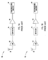
- Fig. 1A generally illustrates one example of a conventional satellite digital audio radio system 90.
- satellite digital audio radio signals are received by an antenna 30.
- the received signals are amplified by a low-noise amplifier 32, filtered by a filter 34, and further amplified by amplifier 36 prior to being provided to SDAR processing circuitry 38.
- the received, amplified, and filtered satellite digital audio radio signals are further processed by SDAR processing circuitry 38 to extract audio and/or other data.
- GPS receivers are also becoming increasingly popular as vehicle accessories. GPS receivers are typically employed in systems to help vehicle drivers and/or passengers determine their location and navigate to various locations. GPS receivers typically receive signals from multiple satellites via an antenna or multiple antennas. By receiving signals from multiple satellites, the GPS receiver is able to determine the location of the GPS receiver, and therefore the vehicle in which the receiver is located, based on the received GPS signals. As with SDAR signals, the GPS signals received by a GPS antenna are typically amplified by a low-noise amplifier coupled to the antenna prior to being provided to additional processing circuitry in the GPS receiver for the calculation of GPS information. This amplification process typically improves the quality of the signal provided to the processing circuitry of the GPS receiver.
- Fig. 1B generally illustrates one example of a conventional GPS system 92 for processing GPS signals.
- GPS signals are received by an antenna 40, amplified by a low-noise amplifier 42, filtered by a filter 44, and amplified again by an amplifier 46 prior to being provided to GPS processing circuitry 48.
- GPS processing circuitry 48 utilizes the amplified, filtered GPS signals to determine location information.
- each of the systems typically requires its own low-noise amplifier (LNA) for amplifying the received GPS and SDAR signals, respectively.
- LNA low-noise amplifier
- the requirement that each system have its own LNA increases the size of the systems and increases the total system cost.
- a system for processing GPS and satellite digital radio signals includes a GPS antenna configured to receive signals transmitted by a GPS satellite, and a satellite digital radio antenna configured to receive satellite digital radio signals.
- the system also includes an amplifier that is electrically coupled to the GPS antenna and satellite antenna. The amplifier is configured to amplify GPS and satellite digital radio signals received by the satellite digital radio antenna and GPS antenna.
- a system for processing GPS and satellite digital radio signals includes an antenna configured to receive signals transmitted by both GPS satellites and satellite digital radio satellites.
- the system also includes an amplifier that is electrically coupled to the antenna. The amplifier is configured to amplify both GPS signals and digital satellite radio signals.
- a method for processing GPS and satellite digital radio signals includes the steps of receiving GPS and satellite digital radio signals, providing the received signals to an amplifier circuit, and amplifying the received signals in the amplifier circuit.
- the method further includes the steps of providing the amplified signal to both a first filter for removing signal components other than GPS components to provide a filtered GPS signal, and a second filter for removing signal components other than satellite digital radio components to provide a filtered satellite digital radio signal.
- the method further includes the steps of providing the filtered GPS signal to GPS processing circuitry, and providing the filtered satellite digital radio signal to satellite digital radio signal processing circuitry.
- FIG. 2 generally illustrates a vehicle 2 including a GPS receiver 4 and satellite digital audio radio (SDAR) receiver 6.
- Vehicle 2 also includes a GPS antenna 10 coupled to GPS receiver 4, and a satellite digital audio radio (SDAR) antenna 8 electrically coupled to SDAR receiver 6.
- broadcast GPS signals are transmitted from GPS satellites 18 and 19 to GPS antenna 10 of vehicle 2.
- the received GPS signals are then provided from GPS antenna 10 to GPS receiver 4, where the signals received by antenna 10 are used by GPS receiver 4 to determine the location of vehicle 2.
- SDAR antenna 8 receives SDAR signals broadcast from SDAR satellite(s) 12.
- SDAR receiver 6 decodes the SDAR signals received via SDAR antenna 8, and extracts audio and/or data from the received signals.
- SDAR signals provided to SDAR antenna 8 from SDAR satellite 12 are provided by a SDAR transmitter 16.
- SDAR transmitter 16 transmits SDAR signals via transmit antenna 14 to SDAR satellite 12.
- the signals are then provided by SDAR satellite 12 to SDAR antenna 8 of vehicle 2, and then to SDAR receiver 6 of vehicle 2.
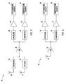
- FIG. 3 generally illustrates a GPS and satellite receiver system 94, according to one embodiment of the present invention.
- the system 94 includes an SDAR antenna 8 coupled to a GPS block 52.
- the SDAR antenna 8 is configured to receive SDAR signals, and provides those signals to GPS block 52.
- GPS block 52 is configured to remove or block signals that are present in the signals received via SDAR antenna 8 that are at frequencies other than SDAR frequencies, such that only SDAR signals are output from GPS block 52.
- GPS block 52 blocks GPS signals.
- System 94 also includes a GPS antenna 10 that is electrically coupled to SDAR block 56.
- GPS antenna 10 is configured to receive GPS signals, and provides those signals to SDAR block 56.
- SDAR block 56 is configured to block signals occurring at frequencies other than a GPS frequency range that are received by GPS antenna 10, or that may be induced in the circuitry coupling GPS antenna 10 to SDAR block 56.
- SDAR block 56 is configured to block frequencies in the SDAR frequency range, such that only GPS signals are output from SDAR block 56.
- the output signal of GPS block 52 is an SDAR signal received by SDAR antenna 8 that does not include GPS signals.
- the output signal of SDAR block 56 is a GPS signal received from GPS antenna 10 that does not include SDAR signals.
- the SDAR signal output of GPS block 52 and the GPS signal output of SDAR block 56 are combined together into a combined input signal which is provided to a low-noise amplifier 58.
- Low-noise amplifier 58 is configured to amplify the combined input signal received from GPS block 52 and SDAR block 56, such that the SDAR and GPS components of the combined input signal are amplified together.
- low-noise amplifier 58 is a two-stage amplifier that is noise-matched to both the GPS and SDAR frequencies.
- low-noise amplifier 58 is electronically coupled to GPS filter 60 and SDAR filter 61.
- GPS filter 60 operates on the output signal from low-noise amplifier 58 to filter the signal, such that signals other than GPS signals are removed from the input signal.
- SDAR filter 61 operates on the input signal received from low-noise amplifier 58 to filter the signal, such that signals at frequencies other than SDAR signals are removed from the input signal.
- SDAR filter 61 is a ceramic filter
- GPS filter 60 is a surface acoustic wave (SAW) filter.
- the filters are configured such that they act as an open circuit for interfering frequency bands. More specifically, GPS filter 60 acts as an open circuit toward signals occurring at other than GPS frequencies, while SDAR filter 61 acts as an open circuit toward signals occurring at other than SDAR frequencies.
- GPS filter 60 is shown coupled to an amplifier 62.
- the filtered GPS signal provided by GPS filter 60 is amplified by amplifier 62. This amplified signal is then provided to GPS processing circuitry 64, which is electronically coupled to amplifier 62. GPS processing circuitry 64 processes the GPS signal, and uses the signal information to determine the location of the GPS receiver and, hence, the location of the vehicle in which the GPS receiver is located.
- the filtered SDAR signal provided by SDAR filter 61 is provided to amplifier 63, which is electronically coupled to SDAR filter 61.
- the amplified SDAR signal provided as an output of amplifier 63 is provided to SDAR processing circuitry 65, which is electronically coupled to the output of amplifier 63. SDAR processing circuitry 65 processes the amplified SDAR signal to extract audio and/or data, and processes the audio and/or data, such that it can be used by users of the SDAR system.
- GPS block 52 and/or SDAR block 56 may be implemented using discrete components, microstrip lines, or other conventional filter construction techniques.
- the system 94 includes current sense circuitry configured to terminate the GPS branch of the circuitry when a GPS antenna is not connected to the system 94.
- FIG. 4 generally illustrates a GPS and SDAR system 92, according to another embodiment of the present invention.
- both GPS and SDAR signals are received via a single antenna 70.
- the received GPS and SDAR signals are provided to a low-noise amplifier 72, where GPS and SDAR components of the received signals are amplified.
- the amplified GPS and SDAR signals are provided from the output of low-noise amplifier 72 to a GPS filter 74.
- GPS filter 74 acts to filter signal components other than GPS signal components from the signal received from low-noise amplifier 72.
- GPS filter 74 then provides the filtered GPS signal to an amplifier 76 that is electrically coupled to GPS filter 74.
- Amplifier 76 provides an amplified filtered GPS signal to GPS processing circuitry 78, which is electrically coupled to amplifier 76.
- GPS processing circuitry 78 processes the received GPS signal to determine the location of a GPS receiver and the vehicle in which it is located.
- SDAR filter 75 operates to filter the GPS and SDAR signals received from low-noise amplifier 72, such that all but the SDAR signals are filtered from the input signal by SDAR filter 75.
- the SDAR filtered signals are provided by SDAR filter 75 to amplifier 77 for amplification.
- Amplifier 77 provides the amplified SDAR signals to SDAR processing circuitry 79 that is electrically coupled to amplifier 77.
- SDAR processing circuitry 79 processes the filtered and amplified SDAR signals to extract audio and/or data, and process the audio and/or data to provide it as output to SDAR system users.
- SDAR and GPS signals received by a single antenna 70 are amplified by a single low-noise amplifier 74 before being provided to additional processing circuitry for extracting and processing GPS and SDAR signals.
- satellite audio signals other than SDAR signals may be processed in the systems generally illustrated in Figs. 3 and 4.
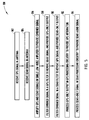
- FIG. 5 generally illustrates a method for processing GPS and satellite digital audio radio (SDAR) signals received by SDAR and GPS systems, according to one embodiment of the present invention.
- GPS signals are received in an antenna.
- SDAR signals are received in an antenna.
- both the GPS and SDAR signals are amplified by a shared low-noise amplifier to provide an amplified combined SDAR GPS signal.
- the combined signal is filtered in a GPS filter to remove SDAR signals, and provides a GPS only output signal.
- the combined signal is filtered in an SDAR filter to remove GPS signals, and provides an SDAR only output.
- the GPS only output signal is processed in GPS processing circuitry to provide GPS information.
- the SDAR only output signal is processed in SDAR processing circuitry to extract audio and/or other SDAR data. It should be appreciated that in an alternate embodiment, satellite audio signals other than SDAR signals are received in an antenna and amplified along with GPS signals by a shared low-noise amplifier.
- the embodiments of the present invention described above advantageously provide for systems and a method for amplifying GPS and SDAR signals in a shared low-noise amplifier prior to providing the signals to SDAR and GPS processing circuitry for the processing of GPS signals, and the extraction of audio and/or data from the SDAR signals.
- the system advantageously employs a reduced number of circuit components to allow reduced size and cost of the systems.
Landscapes
- Engineering & Computer Science (AREA)
- Signal Processing (AREA)
- Physics & Mathematics (AREA)
- Astronomy & Astrophysics (AREA)
- General Physics & Mathematics (AREA)
- Computer Networks & Wireless Communication (AREA)
- Position Fixing By Use Of Radio Waves (AREA)
- Radio Relay Systems (AREA)
- Variable-Direction Aerials And Aerial Arrays (AREA)
- Input Circuits Of Receivers And Coupling Of Receivers And Audio Equipment (AREA)
Applications Claiming Priority (1)
| Application Number | Priority Date | Filing Date | Title |
|---|---|---|---|
| US11/546,637 US7720434B2 (en) | 2006-10-12 | 2006-10-12 | Method and system for processing GPS and satellite digital radio signals using a shared LNA |
Publications (2)
| Publication Number | Publication Date |
|---|---|
| EP1912360A2 true EP1912360A2 (de) | 2008-04-16 |
| EP1912360A3 EP1912360A3 (de) | 2009-02-25 |
Family
ID=38830300
Family Applications (1)
| Application Number | Title | Priority Date | Filing Date |
|---|---|---|---|
| EP20070118060 Ceased EP1912360A3 (de) | 2006-10-12 | 2007-10-08 | Verfahren und System zum Verarbeiten von GPS- und Satelliten-Digitalfunksignalen über ein mehrfach genutztes LNA |
Country Status (2)
| Country | Link |
|---|---|
| US (1) | US7720434B2 (de) |
| EP (1) | EP1912360A3 (de) |
Cited By (1)
| Publication number | Priority date | Publication date | Assignee | Title |
|---|---|---|---|---|
| CN111262605A (zh) * | 2018-11-30 | 2020-06-09 | 锐锋工业股份有限公司 | 复合式天线 |
Families Citing this family (7)
| Publication number | Priority date | Publication date | Assignee | Title |
|---|---|---|---|---|
| US8121564B2 (en) * | 2006-03-06 | 2012-02-21 | Broadcom Corporation | Radio receiver with shared low noise amplifier for multi-standard operation in a single antenna system with loft isolation and flexible gain control |
| US7720434B2 (en) * | 2006-10-12 | 2010-05-18 | Delphi Technologies, Inc. | Method and system for processing GPS and satellite digital radio signals using a shared LNA |
| US7587183B2 (en) * | 2006-12-15 | 2009-09-08 | Laird Technologies, Inc. | Multi-frequency antenna assemblies with DC switching |
| US20120057588A1 (en) * | 2009-03-04 | 2012-03-08 | Laird Technologies, Inc. | Multiple antenna multiplexers, demultiplexers and antenna assemblies |
| US8045592B2 (en) * | 2009-03-04 | 2011-10-25 | Laird Technologies, Inc. | Multiple antenna multiplexers, demultiplexers and antenna assemblies |
| KR101827706B1 (ko) * | 2016-09-20 | 2018-02-12 | 현대자동차주식회사 | 차량 및 차량의 제어 방법 |
| US11187534B2 (en) | 2019-08-22 | 2021-11-30 | Aptiv Technologies Limited | System and method for GNSS reflective surface mapping and position fix estimation |
Citations (4)
| Publication number | Priority date | Publication date | Assignee | Title |
|---|---|---|---|---|
| EP0886384A2 (de) | 1997-06-13 | 1998-12-23 | Lucent Technologies Inc. | Rauscharmer Zweibandverstärker mit einem einzigen Stufe für einen drahtlosen Funkkommunikationsempfänger |
| WO2000003491A1 (en) | 1998-07-13 | 2000-01-20 | Qualcomm Incorporated | Configurable single and dual vcos for dual- and tri-band wireless communication systems |
| US20040072575A1 (en) | 2001-05-17 | 2004-04-15 | Sirf Technology, Inc. | System and method for receiving digital satellite radio and GPS |
| US20060176215A1 (en) | 2005-02-10 | 2006-08-10 | Dubash Noshir B | Reconfigurable downconverter for a multi-band positioning receiver |
Family Cites Families (17)
| Publication number | Priority date | Publication date | Assignee | Title |
|---|---|---|---|---|
| US6538609B2 (en) * | 1999-11-10 | 2003-03-25 | Xm Satellite Radio Inc. | Glass-mountable antenna system with DC and RF coupling |
| US7010263B1 (en) * | 1999-12-14 | 2006-03-07 | Xm Satellite Radio, Inc. | System and method for distributing music and data |
| WO2002075942A2 (en) * | 2001-03-14 | 2002-09-26 | California Institute Of Technology | Concurrent dual-band receiver architecture |
| US7710335B2 (en) * | 2004-05-19 | 2010-05-04 | Delphi Technologies, Inc. | Dual band loop antenna |
| DE102004035064A1 (de) * | 2004-07-20 | 2006-02-16 | Receptec Gmbh | Antennenmodul |
| US8005418B2 (en) * | 2004-08-24 | 2011-08-23 | Delphi Technologies, Inc. | Vehicle oriented switched antenna system |
| WO2006034282A2 (en) * | 2004-09-20 | 2006-03-30 | Panasonic Automotive Systems Company Of America Division Of Panasonic Corporation Of North America | Apparatus having and method for implementing a distributed architecture for receiving and/or transmitting radio frequency signals |
| US20060062580A1 (en) * | 2004-09-22 | 2006-03-23 | Kamran Mahbobi | Apparatus and method for transferring DC power and RF signals through a transparent or substantially transparent medium for antenna reception |
| US20060064725A1 (en) * | 2004-09-22 | 2006-03-23 | Rosum Corporation | Pilot acquisition and local clock calibration with reduced MIPS |
| US7253770B2 (en) | 2004-11-10 | 2007-08-07 | Delphi Technologies, Inc. | Integrated GPS and SDARS antenna |
| US7129895B2 (en) * | 2004-11-15 | 2006-10-31 | Delphi Technologies, Inc. | Multiband concentric mast and microstrip patch antenna arrangement |
| US7620394B2 (en) * | 2005-02-22 | 2009-11-17 | Atc Technologies, Llc | Reusing frequencies of a fixed and/or mobile communications system |
| US20060205359A1 (en) * | 2005-03-14 | 2006-09-14 | Brooks Vincent L | Lifestyle receiver/transmitter for differentiated consumer product |
| US7564907B2 (en) * | 2005-06-15 | 2009-07-21 | Delphi Technologies, Inc. | Technique for providing secondary data in a single-frequency network |
| US7598824B2 (en) * | 2006-03-15 | 2009-10-06 | M/A-Com Technology Solutions Holdings, Inc. | Splitter/combiner circuit |
| US7720434B2 (en) * | 2006-10-12 | 2010-05-18 | Delphi Technologies, Inc. | Method and system for processing GPS and satellite digital radio signals using a shared LNA |
| US7587183B2 (en) * | 2006-12-15 | 2009-09-08 | Laird Technologies, Inc. | Multi-frequency antenna assemblies with DC switching |
-
2006
- 2006-10-12 US US11/546,637 patent/US7720434B2/en not_active Expired - Fee Related
-
2007
- 2007-10-08 EP EP20070118060 patent/EP1912360A3/de not_active Ceased
Patent Citations (4)
| Publication number | Priority date | Publication date | Assignee | Title |
|---|---|---|---|---|
| EP0886384A2 (de) | 1997-06-13 | 1998-12-23 | Lucent Technologies Inc. | Rauscharmer Zweibandverstärker mit einem einzigen Stufe für einen drahtlosen Funkkommunikationsempfänger |
| WO2000003491A1 (en) | 1998-07-13 | 2000-01-20 | Qualcomm Incorporated | Configurable single and dual vcos for dual- and tri-band wireless communication systems |
| US20040072575A1 (en) | 2001-05-17 | 2004-04-15 | Sirf Technology, Inc. | System and method for receiving digital satellite radio and GPS |
| US20060176215A1 (en) | 2005-02-10 | 2006-08-10 | Dubash Noshir B | Reconfigurable downconverter for a multi-band positioning receiver |
Cited By (1)
| Publication number | Priority date | Publication date | Assignee | Title |
|---|---|---|---|---|
| CN111262605A (zh) * | 2018-11-30 | 2020-06-09 | 锐锋工业股份有限公司 | 复合式天线 |
Also Published As
| Publication number | Publication date |
|---|---|
| US20080090514A1 (en) | 2008-04-17 |
| EP1912360A3 (de) | 2009-02-25 |
| US7720434B2 (en) | 2010-05-18 |
Similar Documents
| Publication | Publication Date | Title |
|---|---|---|
| EP1912360A2 (de) | Verfahren und System zum Verarbeiten von GPS- und Satelliten-Digitalfunksignalen über ein mehrfach genutztes LNA | |
| US7650173B2 (en) | Combined antenna module with single output | |
| US6298224B1 (en) | Multiple frequency band receiver | |
| EP1865611A2 (de) | Fahrzeugtelematik-Satellitendatensender mit FM-Funkschaltung | |
| WO2006107874A3 (en) | Transponder tuning and mapping | |
| CN107171758B (zh) | 车辆通信系统 | |
| JP4536285B2 (ja) | ブースタ | |
| US10511335B2 (en) | Method and apparatus for adjacent band RF signal reception | |
| KR100657997B1 (ko) | 통합형 듀플렉스를 이용한 이동통신 중계 장치 | |
| US6549091B1 (en) | Antenna coupler | |
| CN101316144B (zh) | 道路交通信息通信系统用调谐器 | |
| JPH11346168A (ja) | アンテナユニット | |
| KR100990532B1 (ko) | 듀얼 밴드 방송 수신기 | |
| US8559468B2 (en) | Combining a GPS carrier with existing communication carriers over a common coaxial connection | |
| EP2009816A2 (de) | Anordnung und Verfahren zur Kommunikation mehrerer Trägerwällen. | |
| KR200421705Y1 (ko) | Dmb 안테나 모듈 | |
| KR200405575Y1 (ko) | 위성안테나용 엘엔비 | |
| JP2009224908A (ja) | 地上デジタルテレビの受信システム | |
| JP2003125231A (ja) | テレビ受信用ブースタ | |
| CN116413751A (zh) | 用于gnss接收装置的信号处理链 | |
| KR100560000B1 (ko) | 위성방송튜너회로 | |
| JPH0742095Y2 (ja) | ナビゲーション装置 | |
| JP2001217730A (ja) | 衛星信号受信装置 | |
| WO2008002011A1 (en) | Graphic card haveing a dmb function | |
| KR200295550Y1 (ko) | Rf증폭회로 |
Legal Events
| Date | Code | Title | Description |
|---|---|---|---|
| PUAI | Public reference made under article 153(3) epc to a published international application that has entered the european phase |
Free format text: ORIGINAL CODE: 0009012 |
|
| AK | Designated contracting states |
Kind code of ref document: A2 Designated state(s): AT BE BG CH CY CZ DE DK EE ES FI FR GB GR HU IE IS IT LI LT LU LV MC MT NL PL PT RO SE SI SK TR |
|
| AX | Request for extension of the european patent |
Extension state: AL BA HR MK RS |
|
| RIN1 | Information on inventor provided before grant (corrected) |
Inventor name: BALLY, NAZAR F. Inventor name: YEGIN, KORKUT |
|
| RIC1 | Information provided on ipc code assigned before grant |
Ipc: H04B 1/00 20060101ALI20081106BHEP Ipc: H04H 20/59 20080101AFI20080103BHEP |
|
| PUAL | Search report despatched |
Free format text: ORIGINAL CODE: 0009013 |
|
| AK | Designated contracting states |
Kind code of ref document: A3 Designated state(s): AT BE BG CH CY CZ DE DK EE ES FI FR GB GR HU IE IS IT LI LT LU LV MC MT NL PL PT RO SE SI SK TR |
|
| AX | Request for extension of the european patent |
Extension state: AL BA HR MK RS |
|
| 17Q | First examination report despatched |
Effective date: 20090917 |
|
| AKX | Designation fees paid |
Designated state(s): AT BE BG CH CY CZ DE DK EE ES FI FR GB GR HU IE IS IT LI LT LU LV MC MT NL PL PT RO SE SI SK TR |
|
| 17P | Request for examination filed |
Effective date: 20090825 |
|
| STAA | Information on the status of an ep patent application or granted ep patent |
Free format text: STATUS: THE APPLICATION HAS BEEN REFUSED |
|
| 18R | Application refused |
Effective date: 20150412 |