EP1912367A1 - Verfahren zur Dekodierung eines empfangenen multidimensionalen Signals und entsprechende Vorrichtung - Google Patents
Verfahren zur Dekodierung eines empfangenen multidimensionalen Signals und entsprechende Vorrichtung Download PDFInfo
- Publication number
- EP1912367A1 EP1912367A1 EP06301038A EP06301038A EP1912367A1 EP 1912367 A1 EP1912367 A1 EP 1912367A1 EP 06301038 A EP06301038 A EP 06301038A EP 06301038 A EP06301038 A EP 06301038A EP 1912367 A1 EP1912367 A1 EP 1912367A1
- Authority
- EP
- European Patent Office
- Prior art keywords
- matrix
- decoding
- signal
- estimation
- transmitted signal
- Prior art date
- Legal status (The legal status is an assumption and is not a legal conclusion. Google has not performed a legal analysis and makes no representation as to the accuracy of the status listed.)
- Granted
Links
- 238000000034 method Methods 0.000 title claims description 33
- 239000011159 matrix material Substances 0.000 claims abstract description 122
- 239000013598 vector Substances 0.000 claims abstract description 40
- 230000003247 decreasing effect Effects 0.000 claims abstract description 13
- 238000007781 pre-processing Methods 0.000 claims description 10
- 238000000354 decomposition reaction Methods 0.000 claims description 9
- 238000012360 testing method Methods 0.000 description 20
- 230000000875 corresponding effect Effects 0.000 description 17
- 238000001514 detection method Methods 0.000 description 17
- GZPBVLUEICLBOA-UHFFFAOYSA-N 4-(dimethylamino)-3,5-dimethylphenol Chemical compound CN(C)C1=C(C)C=C(O)C=C1C GZPBVLUEICLBOA-UHFFFAOYSA-N 0.000 description 9
- 230000005540 biological transmission Effects 0.000 description 8
- 238000004891 communication Methods 0.000 description 7
- 239000000654 additive Substances 0.000 description 6
- 230000000996 additive effect Effects 0.000 description 6
- 230000001955 cumulated effect Effects 0.000 description 6
- 230000008569 process Effects 0.000 description 5
- 230000009467 reduction Effects 0.000 description 5
- 238000013461 design Methods 0.000 description 3
- 238000001914 filtration Methods 0.000 description 3
- 238000007476 Maximum Likelihood Methods 0.000 description 2
- 238000013459 approach Methods 0.000 description 2
- 238000006243 chemical reaction Methods 0.000 description 2
- 230000006870 function Effects 0.000 description 2
- 238000010845 search algorithm Methods 0.000 description 2
- 230000007480 spreading Effects 0.000 description 2
- 101100129500 Caenorhabditis elegans max-2 gene Proteins 0.000 description 1
- 230000003321 amplification Effects 0.000 description 1
- 230000001143 conditioned effect Effects 0.000 description 1
- 230000002596 correlated effect Effects 0.000 description 1
- 230000009977 dual effect Effects 0.000 description 1
- 238000002592 echocardiography Methods 0.000 description 1
- 230000000694 effects Effects 0.000 description 1
- 238000005562 fading Methods 0.000 description 1
- 238000013507 mapping Methods 0.000 description 1
- 230000006855 networking Effects 0.000 description 1
- 238000003199 nucleic acid amplification method Methods 0.000 description 1
- 230000010363 phase shift Effects 0.000 description 1
- 238000012545 processing Methods 0.000 description 1
- 230000000306 recurrent effect Effects 0.000 description 1
- 230000004044 response Effects 0.000 description 1
- 230000002441 reversible effect Effects 0.000 description 1
- 238000004088 simulation Methods 0.000 description 1
- 230000003595 spectral effect Effects 0.000 description 1
- 230000017105 transposition Effects 0.000 description 1
- 230000002087 whitening effect Effects 0.000 description 1
Images


Classifications
-
- H—ELECTRICITY
- H04—ELECTRIC COMMUNICATION TECHNIQUE
- H04L—TRANSMISSION OF DIGITAL INFORMATION, e.g. TELEGRAPHIC COMMUNICATION
- H04L1/00—Arrangements for detecting or preventing errors in the information received
- H04L1/02—Arrangements for detecting or preventing errors in the information received by diversity reception
- H04L1/06—Arrangements for detecting or preventing errors in the information received by diversity reception using space diversity
- H04L1/0618—Space-time coding
- H04L1/0631—Receiver arrangements
-
- H—ELECTRICITY
- H04—ELECTRIC COMMUNICATION TECHNIQUE
- H04L—TRANSMISSION OF DIGITAL INFORMATION, e.g. TELEGRAPHIC COMMUNICATION
- H04L1/00—Arrangements for detecting or preventing errors in the information received
- H04L1/02—Arrangements for detecting or preventing errors in the information received by diversity reception
- H04L1/06—Arrangements for detecting or preventing errors in the information received by diversity reception using space diversity
- H04L1/0618—Space-time coding
- H04L1/0625—Transmitter arrangements
-
- H—ELECTRICITY
- H04—ELECTRIC COMMUNICATION TECHNIQUE
- H04L—TRANSMISSION OF DIGITAL INFORMATION, e.g. TELEGRAPHIC COMMUNICATION
- H04L1/00—Arrangements for detecting or preventing errors in the information received
- H04L1/02—Arrangements for detecting or preventing errors in the information received by diversity reception
- H04L1/06—Arrangements for detecting or preventing errors in the information received by diversity reception using space diversity
- H04L1/0618—Space-time coding
- H04L1/0637—Properties of the code
- H04L1/0668—Orthogonal systems, e.g. using Alamouti codes
-
- H—ELECTRICITY
- H04—ELECTRIC COMMUNICATION TECHNIQUE
- H04L—TRANSMISSION OF DIGITAL INFORMATION, e.g. TELEGRAPHIC COMMUNICATION
- H04L27/00—Modulated-carrier systems
- H04L27/26—Systems using multi-frequency codes
- H04L27/2601—Multicarrier modulation systems
- H04L27/2647—Arrangements specific to the receiver only
- H04L27/2649—Demodulators
Definitions
- the present invention relates to the field of digital communication. More specifically, it deals with an efficient way to implement a decoding based on a lattice, that is used, for example, in a decoding of a signal transmitted through a noisy channel or multi-user detection.
- An optimal decoder is the one that finds the candidate digital signal that is the most likely, given the received observed signal. Such optimal decoder is said to be optimal in the sense of Maximum Likelihood (or ML).
- a basic approach to perform ML decoding consists in exhaustively enumerating all possible transmitted digital signals and selecting the most likely candidate.
- the selection criterion often consists in computing a Euclidean distance between the filtered candidate and the received observation.
- exhaustive enumeration is very time consuming and most of the time impractical for real time applications. Indeed the number of candidates, and hence the decoder complexity, is exponential with respect to the length of the digital signal. For instance a signal carrying 10 bits may take 1024 (or 2 10 ) different values and all these values need being enumerated in basic ML decoding.
- lattice decoders More appropriate ML decoding algorithms have emerged based on a multidimensional lattice description of the problem, which will be referred to as lattice decoders in the sequel. For instance a signal made of 8 consecutive 16QAM symbols can be described by a 8 dimension lattice with 16 discrete possible values per dimension. After linear filtering, the lattice will remain a lattice but it will be distorted. Instead of enumerating all possible lattice points (16 8 in the present case), lattice decoders will restrict to evaluating lattice points that are in the vicinity of the received signal.
- the invention is aimed at alleviating these drawbacks of the prior art.
- the objective of the invention is to simplify the implementation of a decoding method based on a lattice, while keeping good performances.
- the invention proposes a method of decoding of a multidimensional received signal corresponding to a discrete multidimensional coded signal transmitted through a channel, so-called transmitted signal, characterized in that it comprises the following steps:
- a permutated transmitted signal is a discrete multidimensional coded signal, the components of which are permuted.
- Lattice decoding corresponds to a decoding of a distorted discrete multidimensional signal.
- Sorting of vectors of the first matrix can be considered as sorting of columns and/or sorting of rows of the first matrix, depending whether column or row notation is used.
- the method according to claim 1 characterized in that the first matrix is an equivalent channel matrix equal to a product of a channel matrix by a code matrix.
- the matrix derived from the reordered matrix is the reordered matrix and in that it comprises a QR preprocessing step, the decoding step comprising a decomposition of the reordered matrix.
- the first matrix is a Gram matrix that is equal to the product of the transpose of an equivalent channel matrix by the equivalent channel matrix, the equivalent channel matrix being equal to a product of a channel matrix by a code matrix, the reordered matrix being obtained by sorting of columns and rows of the first matrix according to a decreasing colinearity criterion.
- the method comprises a Cholesky preprocessing step, the decoding step comprising a Cholesky decomposition of the reordered matrix.
- the sorting of vectors of the first matrix according to a decreasing colinearity criterion comprise at least a scalar product computation between two vectors of the first matrix.
- the scalar product can be made on real field or on complex field.
- the scalar product can be normalized or not.
- the discrete multidimensional coded signal comprises data representative of a digital video broadcast signal.
- the inventions also concerns a device of decoding of a multidimensional received signal corresponding to a discrete multidimensional coded signal transmitted through a channel, so-called transmitted signal, characterized in that it comprises the following means:
- This device is for example a receiver, a corresponding chip, a terminal (such as a mobile device, a telecommunication device).
- the invention reduces the complexity of lattice based decoders.
- some types of wireless channels strongly distort the lattice representing the transmitted signal, which induces a larger decoding complexity of lattice decoders (e.g. when the lattice basis is ill conditioned).
- This is the case for strongly spatially correlated channels and/or channels presenting a strong LOS (Line Of Sight) component.
- the invention brings a significant complexity reduction for this type of wireless channels, which has been observed as being a critical channel type that conditions the lattice decoder complexity and dimension the receiver design.
- the invention can be applied to all systems that are based on lattice decoding, especially to decoding of data transmitted through a MIMO channel or to multi-user detection.
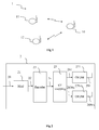
- Figure 1 represents a wireless network 1 comprising several stations 10 to 12. Each station 10 to 12 comprises a transmitter and a receiver using a MIMO (or Multiple Input Multiple Output) antenna system. Station 10 communicates with stations 11 and 12 through a wireless link.
- MIMO Multiple Input Multiple Output
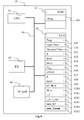
- Figure 2 represents an exemplary architecture of a data transmitter 2 capable of sending data in a way compliant with the invention applied to decoding of a signal transmitted through a MIMO noisy channel.
- the data transmitter 2 can be implemented in stations 10 to 12.
- the transmitter 2 comprises:
- the transmitter 2 receives a binary signal 22 which is digitally modulated by the modulator 21 with a first modulation which is, for instance a QAM modulation (or "Quadrature Amplitude Modulation") (e.g. 16 QAM or 64QAM).
- the modulator 21 generates groups of Q complex QAM symbols S1 to SQ. Q is for example equal to 8.
- the STBC is, for instance, a Golden code such as disclosed in document " The Golden Code: A 2 x 2 Full-Rate Space-Time Code with Non-Vanishing Determinants," which has been written by J.-C. Belfiore, G. Rekaya, E. Viterbo (and published in IEEE Transactions on Information Theory, vol. 51, n. 4, pp. 1432-1436, Apr. 2005 .).
- the STBC is as disclosed in " Space-Time block codes from orthogonal designs" document written by V.Tarokh, H. Jafarkhani, and R. A. Calderbank (and published in IEEE Transactions on Information Theory, vol. 45, pp. 1456-1467, July 1999 ).
- the STBC is based on a complex matrix of dimension N tx *N where N is the time dimension of the STBC.
- the generated STBC 24 is mapped in the time/frequency mapper that transmits a dedicated signal 261 to 26Ntx to each of OFDM modulator 271 to 27Ntx. Then, each modulator 271 to 27Ntx modulates its input signal into an OFDM modulated signal that is sent on an antenna respectively 281 to 28Ntx (after possibly filtering, frequency transposition and amplification as usually done in a radio transmitted signal). As summary, the STBC codeword 24 is then sent on a MIMO channel.
- Such a transmitter system is disclosed in " Space-frequency coded broadband OFDM systems", written by H. Bölcskei and A. J. Paulraj (and published in Proc. Wireless Commun. Networking Conf., Chicago, IL, Sept. 23-28, 2000, pp. 1-6 ).
- a single carrier modulation can replace the OFDM modulation (or any multi carrier modulation such IOTA (for "Isotropic Orthogonal Transform Algorithm")). Then, a time/frequency mapper 25 and the OFDM modulators 271 to 27Ntx are replaced by at least two single carrier modulators associated each with a antenna.
- IOTA Independent Orthogonal Transform Algorithm
- the first modulation can be of any digital modulation, e.g. nPSK (for “Phase Shift Keying with n phase values) or nQAM (eg with n equals to 16, 32, 64, 256).
- nPSK Phase Shift Keying with n phase values
- nQAM e.g with n equals to 16, 32, 64, 256.
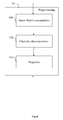
- Figure 3 represents an exemplary architecture of a data receiver 3 according to a specific embodiment of the invention.
- the receiver 3 receives a signal send by the transmitter 2 through a wireless channel.
- This channel is noisy and comprise Additive White Gaussian Noise (or AWGN) and possibly other noise such as interferences.
- the sent signal can also be affected by multipath echos and/or Doppler effect.
- the data receiver 3 can be implemented in stations 10 to 12.
- the receiver 3 comprises:
- the receiver 3 matches the transmitter 2 (especially for modulation and code used by the transmitter). Then, according to variants using single carrier modulation inside the transmitter, the OFDM demodulators are replaced by the corresponding single carrier demodulators.
- the receiver 3 comprises Nrx receive antennas 301 to 30 Nrx so that the received signal 301 to 30 Nrx can be represented by a Nrx*N matrix, or equivalently a ( Nrx*N)* 1 vector R.
- N is, for instance, equal to 2 and represents the time and/or frequency range occupied by the STBC.
- the space/time coding process takes place with real inputs (instead of complex inputs). Then, the C matrix is a real matrix with a dimension (2 Ntx*N) *(2 Q) .
- ⁇ 2 represents the variance of the resulting whitened noise.
- the time/frequency demapper 33 received demodulated signal from OFDM demodulators 311 to 31 Nrx and is doing the reverse mapping (corresponding to dual operation of mapper 25). It provides a demapped signal to decoder 35.
- the decoder 35 is a lattice decoder and is particularly well suited to perform ML decoding of the Space-Time Block encoded signal.
- the decoder 35 is exploiting the properties of the noise distribution by selecting points in a lattice that are between two spheres around a received point, the decoded point being chosen among selected points. This enables a reduction of the decoder complexity as the number of selected points can be lowered in comparison with a state of art decoder where the selected points are within one sphere around the received point. Actually, according to the invention, it is unlikely that ML decoding would choose points of the lattice that are too close to the received point as decoded points. Then, the decoder does not select these points as potential candidates for decoded points. Reduction of number of selected points enables a dramatic reduction of decoding complexity (the decoding complexity depend of the level of noise and is increasing with the number of selected points).
- FIG 7 represents the distribution of received data received by the receiver 3.
- Figure 7 gives a simplified lattice representation 7 of the decoding problem. The problem is illustrated in the case where the dimension K is 2 (Q equals 1) for the sake of illustration clarity. Those two dimensions are represented respectively by lines 77 and lines 78. Intersections of lines 77 and 78 corresponds to points of the lattice 7.
- the transmitted signal (which is the ML point here), is a lattice point 750 represented by US' 0 .
- the lattice points that can be considered as candidates for ML decoding are, according to the invention, in a search space between two spheres 71 and 72:
- a lattice point 74 is within the sphere 71 and is not among candidate points for the ML decoding according to the invention (whereas this point would have been selected by a state of the art decoding method).
- Lattice points 760 to 764 are outside the sphere 72 and are not among candidate points for the ML decoding.
- Lattice points 750 to 754 are in sphere 72 and outside sphere 71; then, these points are considered as candidates by the decoder.
- the horizontal axis 83 represents the normalized distance to the received point.
- the vertical axis 82 corresponds to the distribution of samples for a given normalized distance.
- the distances dmin and dmax are defined such that Pr( ⁇ > dmax ) equals 10 -2 and Pr( ⁇ ⁇ dmin ) equals 10 -2 . These probabilities are example values. It can be noted that area 801 corresponding to normalized distance lower than dmin and area 802 corresponding to normalized distance higher than dmax are very small (each having a normalized surface of 10 -2 ) compared to the middle area 800, where the normalized distance is greater than dmin and lower than dmax . On the given example, dmin is around 0.025 that is significant. Then, it shows that it is very unlikely that the distance between a point corresponding to the coded point (without noise) and the actual received point is below dmin.
- dmax gives an initial value for the radius of the sphere S(Rp,r) within which the search will take place.
- the probability that the transmitted signal is outside this sphere is 10 -2 . Setting the initial radius to dmax therefore allows reducing the initial search space, and hence the decoding complexity, for a given level of performance.
- dmin is introduced and can advantageously be used in the decoding process according to two ways, as follows:
- the integrated function is the probability density function (or pdf) of ⁇ 2
- p 0 is the desired probability threshold of the event (i.e. the transmitted signal is in S( R p, dmin )).
- dmin / ⁇ can be determined according to a predefined value of po.
- dmin can be determined by using approximations of above equation (e.g. by using a first or second orders of a Taylor series).
- Figure 4 represents an exemplary architecture of the decoder 35 of the receiver 3.
- Decoder 35 comprises following elements that are linked together by a data and address bus 44:
- the word « register » used in the specification can correspond to area of small capacity (some bits) or to very large area (e.g. a whole program or large amount of received or decoded data).
- ROM 42 comprises a program 420.
- Algorithm of the method according to the invention are stored in the ROM 42.
- the CPU 41 uploads the program 420 in the RAM and executes the corresponding instructions.
- RAM 43 comprises:
- the decoder 35 is implemented in pure hardware configuration (e.g. in one or several FPGA, ASIC or VLSI with corresponding memory) or in a configuration using both VLSI and DSP.
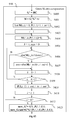
- Figure 5 represents a decoding method implemented in the decoder 35.
- the decoding begins with a initialization step 50, wherein different parameters of the method are set to their initial value(s).
- the decoder 35 waits for and receives a signal from demapper 33.
- the CPU 41 makes a channel estimation 52 based upon the received signal (associated to one transmitted block) or part of it.
- the estimation 52 is based upon several received signals (or part of them), each being associated to a transmitted block.
- the estimation 52 is not done at each reception of signal corresponding to one transmitted block; in this case, it may be done when necessary according to the channel changes (e.g. every 1 ms).
- step 53 CPU 41 computes ⁇ using, for example, a pilot sequence and determines dmin as explained above and possibly dmax in a similar way.
- step 53 is executed after each channel estimation 52.
- step 53 is not done at each reception of signal corresponding to one transmitted block.
- CPU 41 is executing a preprocessing step 54.
- CPU 41 is enumerating lattice points and selects decoded point in a step 55.
- step 56 the components of the decoded point are inversely permutated according to the permutation produced by step 540.
- step 51 is reiterated.
- step 54 is performed by the DSP and step 55 by a VLSI (e.g. ASIC or FPGA).
- VLSI e.g. ASIC or FPGA
- FIG. 6 details preprocessing step 54. A brief explanation of the decoding method is first disclosed hereafter.
- CS in equation (1) denotes the STB (Space Time Block) encoded signal.
- the encoding process is represented by complex matrix multiplications in the present case but from a more general point of view, it shall be represented by real matrices where the real and imaginary parts of S are encoded separately.
- the STBC scheme disclosed in Alamouti document (“Space-Time block coding: A simple transmitter diversity technique for wireless communications”) can only be represented with such real notations.
- R R R I ⁇ R ⁇ H R - H I H I H R ⁇ C ⁇ ⁇ G ⁇ ⁇ S R S I ⁇ S ⁇ + v R v I ⁇ v ⁇
- C' is the STBC encoding matrix in real notations
- R and (.) / denote respectively the real and imaginary parts of a complex number or matrix.
- the dimension of the input signal S' which is the problem dimension
- K 2Q.
- lattice decoding algorithms more advantageously use a triangular matrix as a lattice basis, so that the starting point of the search algorithm is not (2) but it is given by equation (3):
- U is a upper triangular KxK matrix.
- U is the new lattice basis that is used by lattice decoding algorithms.
- the time/frequency dimension N is replaced by a time dimension if a single carrier modulation is used.
- the STBC decoder finds the best estimate of the transmitted signal S .
- the lattice decoders use a lattice representation of the problem, where each lattice point is a potential transmitted signal. From this lattice representation, they enumerate a reduced number of candidate signals with respect to what would do a basic ML decoder. For instance, with Q equals to 8 and using 16QAM constellation, a basic ML decoder will enumerate 16 8 candidates to decode a STBC codeword and the lattice decoders will only enumerate very few of them.
- the search space is reduced to the space between two spheres 71 and 72 of radius dmin and dmax .
- the decoding algorithm can be split into two main phases:
- the preprocessing phase 54 begins with a computation 540 of Gram Matrix.
- Gram matrix corresponds to a multiplication of an equivalent channel matrix new_G' by its transpose new_G' t .
- the received signal is projected on the matrix computed on step 541. This projection first multiplies the received signal R' by new_G' t and then by the inverse of U t .
- step 541 is replaced by a QR decomposition of a new equivalent channel matrix (new_G '), new_G ' being equal to QU where Q is an orthogonal matrix and U an upper triangular matrix.
- step 542 comprises a multiplication by Q t .
- Figure 12 represents details Gram Matrix computation 540.
- the step 540 begins with a step 5400 of computation of an equivalent channel matrix G' equal to the product HC .
- Step 540 consists in permuting the columns of the real matrix G' of equation (2) according to a particular criterion based on the components of the Gram matrix G' t G' .
- R R R I ⁇ R ⁇ H R - H I H I H R ⁇ C ⁇ ⁇ G ⁇ ⁇ S R S I ⁇ S ⁇ + v R v I ⁇ v ⁇
- the lattice basis is permuted so that successive dimensions that are addressed in the search phase are as collinear as possible.
- the component ( G' t G' ) ij contains the scalar product between i th and j th basis vectors that are respectively i th and j th column vectors of G', so that the larger abs(( G' t G' ) ij ), the more collinear the i th and j th vectors.
- complex notations are used (instead of real notation), the vectorial space on the field of real numbers is replaced by the vectorial space on the field of complex numbers and the scalar product (and associated norm) is changed accordingly.
- a matrix M is computed, M being equal to the product G' t G' plus ⁇ , where ⁇ is smaller than the smallest absolute value of M.
- ⁇ is smaller than the smallest absolute value of M.
- the use of ⁇ allows that the step 540 also produces a permutation of (1,.., K ) even when M is diagonal.
- the product G' t G' corresponds to computation of non normalized scalar products of vectors of G'.
- the diagonal of M is set to 0 ( M ( i,i ) equals 0 for every value of i from 1 to K ). This avoids producing the identity permutation or a permutation only based on the lattice basis vector norms, which performs worse than the present criterion.
- i_in a permutation vector
- the first dimension dealt with is the one corresponding to the smallest or largest diagonal value of G' t G' (this enables processing of the dimension with largest energy first, in the lattice decoding step).
- the vectors of M are sorted according to a decreasing colinearity criterion, vectors being compared 2 by 2 (that enables a dimension permutation).
- a counter i is set to 1.
- the element M ( i_in, P (1,1: i )) is set to 0.
- (1: i ) denotes the vector [1,2,...,i] so that P (1,1: i ) denotes the first i components of the row 1 of P.
- M ( i_in, P (1,1: i )) denotes the elements of row i_in of M having column indexes P (1,1: i ).
- This initialization 5404 of the i_in row of M is made to avoid producing twice the same index in the permutation vector (and hence not producing a permutation).
- a counter k is set to 1 and a variable max is set to 0.
- the CPU 41 checks if the absolute value of M ( i_in,k ) is superior or equal to max .
- max is set to the absolute value of M ( i_in,k ) and an index i_out is set to k.
- the index i_out corresponding to the basis vector is searched.
- the index i_out is the most collinear (i.e. largest absolute value of scalar product) with respect to the current basis vector i_in .
- the CPU 41 checks if the counter k is equal to K +1.
- step 5410 the value of P(1, i +1) is set to i_out . Adjacent dimensions in the permutation now have highest absolute value of scalar product. During, this step i_in is also set to i_out.
- the CPU 41 checks if i equals K.
- step 5404 is reiterated.
- This new matrices new_Gram and new_G' are the ones that will serve for the lattice decoding preprocessing phase (QR or Cholesky decomposition).
- step 541 is replaced by a QR decomposition of new_G', producing a new_Gram matrix is not necessary (during step 5413).
- M is equal to the product G ' t G and, it is checked whether M is diagonal or not. If so, steps 5402 to 5412 are replaced by a permutation that is only based on the diagonal values of M and more especially that comprises an ordering of its elements according to decreasing (or increasing) values of diagonal values.
- step 5401 can be replaced by step 13 disclosed in figure 13. According to this variant the scalar product between vectors of G' is normalized.
- Step 14 begins by a step 130 of set of a counter i to 0.
- a counter j is set to 0.
- the element M(i,j) is set to G' t G'(i,j) /sqrt( G' t G '(i,i)* G' t G '(j,j)), this scalar product being normalized.
- step 133 the CPU 41 checks if j equals K. If no, step 133 is reiterated.
- step 136 the CPU 41 checks if i equals K . If no, step 131 is reiterated. If yes, during a step 137, M is set to the sum M + ⁇ .
- Figure 9 and 10 detail decoding step 55, which comprises an enumeration of candidate lattice points that takes into account a minimum distance dmin.
- ML points are searched among lattice points (using the basis U) that are in a space between spheres 71 and 72 of radius respectively dmin and dmax .
- this search phase is implemented in different ways.
- Figures 9 and 10 detail two different embodiments.
- Other alternative search algorithms can be implemented according to the invention, these algorithm being based on algorithms such as so called tree search, branch and bound and wherein the ML points are searched in a space outside a sphere of a minimum radius dmin .
- Embodiment of figure 9 is based upon a sphere decoding (as the algorithm of Viterbo/Boutros) with a restriction of the selection lattice points that must not be too close to the received signal point (the distance between the selected points and the received signal point is greater than dmin ).
- dmin the distance between the selected points and the received signal point is greater than dmin .
- the ML point is in the largest sphere.
- This approach allows to define bounds for each component (or dimension) of the candidate signals S, within which discrete components of the signal are enumerated. That can be summarized by the equation: d min 2 ⁇ U - 1 ⁇ R p - S t ⁇ U t ⁇ U ⁇ U - 1 ⁇ R p - S ⁇ d max 2
- the components of S further satisfy the modulation constellation boundaries constraints as S components are a constellation point. For instance, if a 16QAM modulation is used, the components of S satisfy -3 ⁇ Si ⁇ 3.
- the step 55 begins with an initialization step 550 where a cumulated metric DDim associated to each dimension is set to 0, a maximum distance DMAX is set to infinity and a current dimension index Dim is set to K (lattice dimension).
Landscapes
- Engineering & Computer Science (AREA)
- Computer Networks & Wireless Communication (AREA)
- Signal Processing (AREA)
- Radio Transmission System (AREA)
- Compression, Expansion, Code Conversion, And Decoders (AREA)
- Reduction Or Emphasis Of Bandwidth Of Signals (AREA)
- Communication Control (AREA)
Priority Applications (3)
| Application Number | Priority Date | Filing Date | Title |
|---|---|---|---|
| EP06301038A EP1912367B1 (de) | 2006-10-11 | 2006-10-11 | Verfahren zur Dekodierung eines empfangenen multidimensionalen Signals und entsprechende Vorrichtung |
| AT06301038T ATE492082T1 (de) | 2006-10-11 | 2006-10-11 | Verfahren zur dekodierung eines empfangenen multidimensionalen signals und entsprechende vorrichtung |
| DE602006018942T DE602006018942D1 (de) | 2006-10-11 | 2006-10-11 | Verfahren zur Dekodierung eines empfangenen multidimensionalen Signals und entsprechende Vorrichtung |
Applications Claiming Priority (1)
| Application Number | Priority Date | Filing Date | Title |
|---|---|---|---|
| EP06301038A EP1912367B1 (de) | 2006-10-11 | 2006-10-11 | Verfahren zur Dekodierung eines empfangenen multidimensionalen Signals und entsprechende Vorrichtung |
Publications (2)
| Publication Number | Publication Date |
|---|---|
| EP1912367A1 true EP1912367A1 (de) | 2008-04-16 |
| EP1912367B1 EP1912367B1 (de) | 2010-12-15 |
Family
ID=37943956
Family Applications (1)
| Application Number | Title | Priority Date | Filing Date |
|---|---|---|---|
| EP06301038A Not-in-force EP1912367B1 (de) | 2006-10-11 | 2006-10-11 | Verfahren zur Dekodierung eines empfangenen multidimensionalen Signals und entsprechende Vorrichtung |
Country Status (3)
| Country | Link |
|---|---|
| EP (1) | EP1912367B1 (de) |
| AT (1) | ATE492082T1 (de) |
| DE (1) | DE602006018942D1 (de) |
Cited By (2)
| Publication number | Priority date | Publication date | Assignee | Title |
|---|---|---|---|---|
| EP2075927A1 (de) | 2007-12-21 | 2009-07-01 | Thomson Licensing | Verfahren zur Sendung von mindestens einem Datenpaket über verschiedene Antennen und entsprechendes Empfangsverfahren |
| CN104682963A (zh) * | 2015-03-03 | 2015-06-03 | 北京邮电大学 | 一种信号循环平稳特性的重构方法 |
Citations (5)
| Publication number | Priority date | Publication date | Assignee | Title |
|---|---|---|---|---|
| WO2002060082A2 (en) * | 2001-01-25 | 2002-08-01 | Interdigital Technology Corporation | Simplified block linear equalizer with block space time transmit diversity |
| WO2003055068A1 (en) * | 2001-12-21 | 2003-07-03 | Nokia Corporation | A method for signal estimation in a receiver |
| WO2004054191A1 (en) * | 2002-12-11 | 2004-06-24 | Qualcomm Incorporated | Derivation of eigenvectors for spatial processing in mimo communication systems |
| FR2863422A1 (fr) | 2003-12-04 | 2005-06-10 | France Telecom | Procede d'emission multi-antennes d'un signal precode lineairement,procede de reception, signal et dispositifs correspondants |
| EP1560347A1 (de) * | 2001-01-25 | 2005-08-03 | InterDigital Patent Corporation | Vereinfachter Block-Linearer Entzerrer mit Raum-Zeit Sende-Diversität |
-
2006
- 2006-10-11 AT AT06301038T patent/ATE492082T1/de not_active IP Right Cessation
- 2006-10-11 EP EP06301038A patent/EP1912367B1/de not_active Not-in-force
- 2006-10-11 DE DE602006018942T patent/DE602006018942D1/de active Active
Patent Citations (5)
| Publication number | Priority date | Publication date | Assignee | Title |
|---|---|---|---|---|
| WO2002060082A2 (en) * | 2001-01-25 | 2002-08-01 | Interdigital Technology Corporation | Simplified block linear equalizer with block space time transmit diversity |
| EP1560347A1 (de) * | 2001-01-25 | 2005-08-03 | InterDigital Patent Corporation | Vereinfachter Block-Linearer Entzerrer mit Raum-Zeit Sende-Diversität |
| WO2003055068A1 (en) * | 2001-12-21 | 2003-07-03 | Nokia Corporation | A method for signal estimation in a receiver |
| WO2004054191A1 (en) * | 2002-12-11 | 2004-06-24 | Qualcomm Incorporated | Derivation of eigenvectors for spatial processing in mimo communication systems |
| FR2863422A1 (fr) | 2003-12-04 | 2005-06-10 | France Telecom | Procede d'emission multi-antennes d'un signal precode lineairement,procede de reception, signal et dispositifs correspondants |
Non-Patent Citations (6)
| Title |
|---|
| BURG & AI: "VLSI implementation of MIMO detection using the sphere decoding algorithm", SOLID-STATE CIRCUITS, IEEE JOURNAL, vol. 40, no. 7, July 2005 (2005-07-01), pages 1566 - 1577 |
| DAMEN & AI: "On maximum-likelihood detection and the search for the closest lattice point", INFORMATION THEORY, IEEE TRANSACTIONS, vol. 49, no. 10, October 2003 (2003-10-01), pages 238 - 2402 |
| KOHNO K ET AL: "An adaptive super-exponential deflation algorithm for blind deconvolution of MIMO systems using the QR-factorization of matrix algebra", CIRCUITS AND SYSTEMS, 2004. MWSCAS '04. THE 2004 47TH MIDWEST SYMPOSIUM ON HIROSHIMA, JAPAN JULY 25-28, 2004, PISCATAWAY, NJ, USA,IEEE, vol. 3, 25 July 2004 (2004-07-25), pages III419 - III422, XP010739231, ISBN: 0-7803-8346-X * |
| MURUGANATHAN S D ET AL: "A recursive qr detector for space-frequency block coded ofdm systems with four transmit antennas", COMMUNICATIONS, COMPUTERS AND SIGNAL PROCESSING, 2005. PACRIM. 2005 IEEE PACIFIC RIM CONFERENCE ON VICTORIA, BC, CANADA 24-26 AUG., 2005, PISCATAWAY, NJ, USA,IEEE, 24 August 2005 (2005-08-24), pages 510 - 513, XP010841561, ISBN: 0-7803-9195-0 * |
| PENG LIU ET AL: "A new efficient MIMO detection algorithm based on cholesky decomposition", ADVANCED COMMUNICATION TECHNOLOGY, 2004. THE 6TH INTERNATIONAL CONFERENCE ON PHOENIX PARK, KOREA FEB. 9-11, 2004, PISCATAWAY, NJ, USA,IEEE, vol. 1, 9 February 2004 (2004-02-09), pages 264 - 268, XP010702891, ISBN: 89-5519-119-7 * |
| WÜBBEN D ET AL: "Efficient algorithm for decoding layered space-time codes", ELECTRONICS LETTERS, IEE STEVENAGE, GB, vol. 37, no. 22, 25 October 2001 (2001-10-25), pages 1348 - 1350, XP006017406, ISSN: 0013-5194 * |
Cited By (2)
| Publication number | Priority date | Publication date | Assignee | Title |
|---|---|---|---|---|
| EP2075927A1 (de) | 2007-12-21 | 2009-07-01 | Thomson Licensing | Verfahren zur Sendung von mindestens einem Datenpaket über verschiedene Antennen und entsprechendes Empfangsverfahren |
| CN104682963A (zh) * | 2015-03-03 | 2015-06-03 | 北京邮电大学 | 一种信号循环平稳特性的重构方法 |
Also Published As
| Publication number | Publication date |
|---|---|
| ATE492082T1 (de) | 2011-01-15 |
| EP1912367B1 (de) | 2010-12-15 |
| DE602006018942D1 (de) | 2011-01-27 |
Similar Documents
| Publication | Publication Date | Title |
|---|---|---|
| US8514795B2 (en) | Method of adaptive frequency assignment to a plurality of antennas | |
| Hochwald et al. | Unitary space-time modulation for multiple-antenna communications in Rayleigh flat fading | |
| US7430243B2 (en) | Space-time-frequency coded OFDM communications over frequency-selective fading channels | |
| US7573805B2 (en) | Data transmission and reception method and apparatus | |
| KR100918717B1 (ko) | 다입다출력 직교주파수분할다중화 이동통신 시스템에서의신호 시퀀스 추정 방법 및 장치 | |
| US8421654B2 (en) | Method of decoding a signal implementing a progressive construction of a decoding tree, corresponding computer program and decoding device | |
| US20040082303A1 (en) | Space-time doppler coding schemes for time-selective wireless communication channels | |
| US20050094740A1 (en) | Multiple-antenna partially coherent constellations for multi-carrier systems | |
| EP1850506A1 (de) | Zeit-raum blockvorcodierverfahren in einer mehrbenutzerabwärtsverbindung | |
| CN107094063B (zh) | 半穷举迭代块解码方法和设备 | |
| US20070206697A1 (en) | Signal receiving method and signal receiving equipment for multiple input multiple output wireless communication system | |
| US8842755B2 (en) | Process for decoding ALAMOUTI block code in an OFDM system, and receiver for the same | |
| EP3697010B1 (de) | Datenverarbeitungsverfahren und -vorrichtung | |
| US20060126489A1 (en) | Transmitter diversity method for ofdm system | |
| US8693602B2 (en) | Method and device for mono- and multi-antenna reception for Alamouti-type links | |
| EP1912367B1 (de) | Verfahren zur Dekodierung eines empfangenen multidimensionalen Signals und entsprechende Vorrichtung | |
| EP1931075B1 (de) | Verfahren zur Dekodierung eines empfangenen mehrdimensionalen Signals | |
| EP1912368B1 (de) | Verfahren zur Dekodierung eines empfangenen multidimensionalen Signals und entsprechende Vorrichtung | |
| EP1912369A1 (de) | Verfahren zur Dekodierung eines empfangenen multidimensionalen Signals und entsprechende Vorrichtung | |
| EP1912370A1 (de) | Vorrichtung zur Dekodierung eines empfangenen multidimensionalen Signals und entsprechendes System | |
| de Mello et al. | Spectrum efficient GFDM based on faster than Nyquist signaling | |
| Le et al. | Efficient algorithm for blind detection of orthogonal space-time block codes | |
| KR101225649B1 (ko) | 다중 안테나 통신시스템의 채널추정 장치 및 방법 | |
| Sharma et al. | Maximum Likelihood Detection for Cooperative Diversity in MIMO Relay Channels. | |
| Shubhi et al. | Pseudo distance for trellis coded modulation in overloaded MIMO OFDM with sphere decoding |
Legal Events
| Date | Code | Title | Description |
|---|---|---|---|
| PUAI | Public reference made under article 153(3) epc to a published international application that has entered the european phase |
Free format text: ORIGINAL CODE: 0009012 |
|
| AK | Designated contracting states |
Kind code of ref document: A1 Designated state(s): AT BE BG CH CY CZ DE DK EE ES FI FR GB GR HU IE IS IT LI LT LU LV MC NL PL PT RO SE SI SK TR |
|
| AX | Request for extension of the european patent |
Extension state: AL BA HR MK RS |
|
| 17P | Request for examination filed |
Effective date: 20081014 |
|
| 17Q | First examination report despatched |
Effective date: 20081113 |
|
| AKX | Designation fees paid |
Designated state(s): AT BE BG CH CY CZ DE DK EE ES FI FR GB GR HU IE IS IT LI LT LU LV MC NL PL PT RO SE SI SK TR |
|
| RAP1 | Party data changed (applicant data changed or rights of an application transferred) |
Owner name: THOMSON LICENSING |
|
| GRAP | Despatch of communication of intention to grant a patent |
Free format text: ORIGINAL CODE: EPIDOSNIGR1 |
|
| RIN1 | Information on inventor provided before grant (corrected) |
Inventor name: GUEGUEN, ARNAUD |
|
| GRAS | Grant fee paid |
Free format text: ORIGINAL CODE: EPIDOSNIGR3 |
|
| GRAA | (expected) grant |
Free format text: ORIGINAL CODE: 0009210 |
|
| AK | Designated contracting states |
Kind code of ref document: B1 Designated state(s): AT BE BG CH CY CZ DE DK EE ES FI FR GB GR HU IE IS IT LI LT LU LV MC NL PL PT RO SE SI SK TR |
|
| REG | Reference to a national code |
Ref country code: CH Ref legal event code: EP Ref country code: GB Ref legal event code: FG4D |
|
| REG | Reference to a national code |
Ref country code: IE Ref legal event code: FG4D |
|
| REF | Corresponds to: |
Ref document number: 602006018942 Country of ref document: DE Date of ref document: 20110127 Kind code of ref document: P |
|
| REG | Reference to a national code |
Ref country code: NL Ref legal event code: VDEP Effective date: 20101215 |
|
| PG25 | Lapsed in a contracting state [announced via postgrant information from national office to epo] |
Ref country code: LT Free format text: LAPSE BECAUSE OF FAILURE TO SUBMIT A TRANSLATION OF THE DESCRIPTION OR TO PAY THE FEE WITHIN THE PRESCRIBED TIME-LIMIT Effective date: 20101215 |
|
| LTIE | Lt: invalidation of european patent or patent extension |
Effective date: 20101215 |
|
| PG25 | Lapsed in a contracting state [announced via postgrant information from national office to epo] |
Ref country code: BG Free format text: LAPSE BECAUSE OF FAILURE TO SUBMIT A TRANSLATION OF THE DESCRIPTION OR TO PAY THE FEE WITHIN THE PRESCRIBED TIME-LIMIT Effective date: 20110315 Ref country code: SI Free format text: LAPSE BECAUSE OF FAILURE TO SUBMIT A TRANSLATION OF THE DESCRIPTION OR TO PAY THE FEE WITHIN THE PRESCRIBED TIME-LIMIT Effective date: 20101215 Ref country code: AT Free format text: LAPSE BECAUSE OF FAILURE TO SUBMIT A TRANSLATION OF THE DESCRIPTION OR TO PAY THE FEE WITHIN THE PRESCRIBED TIME-LIMIT Effective date: 20101215 Ref country code: SE Free format text: LAPSE BECAUSE OF FAILURE TO SUBMIT A TRANSLATION OF THE DESCRIPTION OR TO PAY THE FEE WITHIN THE PRESCRIBED TIME-LIMIT Effective date: 20101215 Ref country code: CY Free format text: LAPSE BECAUSE OF FAILURE TO SUBMIT A TRANSLATION OF THE DESCRIPTION OR TO PAY THE FEE WITHIN THE PRESCRIBED TIME-LIMIT Effective date: 20101215 Ref country code: NL Free format text: LAPSE BECAUSE OF FAILURE TO SUBMIT A TRANSLATION OF THE DESCRIPTION OR TO PAY THE FEE WITHIN THE PRESCRIBED TIME-LIMIT Effective date: 20101215 Ref country code: LV Free format text: LAPSE BECAUSE OF FAILURE TO SUBMIT A TRANSLATION OF THE DESCRIPTION OR TO PAY THE FEE WITHIN THE PRESCRIBED TIME-LIMIT Effective date: 20101215 Ref country code: FI Free format text: LAPSE BECAUSE OF FAILURE TO SUBMIT A TRANSLATION OF THE DESCRIPTION OR TO PAY THE FEE WITHIN THE PRESCRIBED TIME-LIMIT Effective date: 20101215 |
|
| PG25 | Lapsed in a contracting state [announced via postgrant information from national office to epo] |
Ref country code: CZ Free format text: LAPSE BECAUSE OF FAILURE TO SUBMIT A TRANSLATION OF THE DESCRIPTION OR TO PAY THE FEE WITHIN THE PRESCRIBED TIME-LIMIT Effective date: 20101215 Ref country code: EE Free format text: LAPSE BECAUSE OF FAILURE TO SUBMIT A TRANSLATION OF THE DESCRIPTION OR TO PAY THE FEE WITHIN THE PRESCRIBED TIME-LIMIT Effective date: 20101215 Ref country code: PT Free format text: LAPSE BECAUSE OF FAILURE TO SUBMIT A TRANSLATION OF THE DESCRIPTION OR TO PAY THE FEE WITHIN THE PRESCRIBED TIME-LIMIT Effective date: 20110415 Ref country code: BE Free format text: LAPSE BECAUSE OF FAILURE TO SUBMIT A TRANSLATION OF THE DESCRIPTION OR TO PAY THE FEE WITHIN THE PRESCRIBED TIME-LIMIT Effective date: 20101215 Ref country code: GR Free format text: LAPSE BECAUSE OF FAILURE TO SUBMIT A TRANSLATION OF THE DESCRIPTION OR TO PAY THE FEE WITHIN THE PRESCRIBED TIME-LIMIT Effective date: 20110316 Ref country code: IS Free format text: LAPSE BECAUSE OF FAILURE TO SUBMIT A TRANSLATION OF THE DESCRIPTION OR TO PAY THE FEE WITHIN THE PRESCRIBED TIME-LIMIT Effective date: 20110415 Ref country code: ES Free format text: LAPSE BECAUSE OF FAILURE TO SUBMIT A TRANSLATION OF THE DESCRIPTION OR TO PAY THE FEE WITHIN THE PRESCRIBED TIME-LIMIT Effective date: 20110326 |
|
| PG25 | Lapsed in a contracting state [announced via postgrant information from national office to epo] |
Ref country code: SK Free format text: LAPSE BECAUSE OF FAILURE TO SUBMIT A TRANSLATION OF THE DESCRIPTION OR TO PAY THE FEE WITHIN THE PRESCRIBED TIME-LIMIT Effective date: 20101215 Ref country code: RO Free format text: LAPSE BECAUSE OF FAILURE TO SUBMIT A TRANSLATION OF THE DESCRIPTION OR TO PAY THE FEE WITHIN THE PRESCRIBED TIME-LIMIT Effective date: 20101215 Ref country code: PL Free format text: LAPSE BECAUSE OF FAILURE TO SUBMIT A TRANSLATION OF THE DESCRIPTION OR TO PAY THE FEE WITHIN THE PRESCRIBED TIME-LIMIT Effective date: 20101215 |
|
| PLBE | No opposition filed within time limit |
Free format text: ORIGINAL CODE: 0009261 |
|
| STAA | Information on the status of an ep patent application or granted ep patent |
Free format text: STATUS: NO OPPOSITION FILED WITHIN TIME LIMIT |
|
| PG25 | Lapsed in a contracting state [announced via postgrant information from national office to epo] |
Ref country code: DK Free format text: LAPSE BECAUSE OF FAILURE TO SUBMIT A TRANSLATION OF THE DESCRIPTION OR TO PAY THE FEE WITHIN THE PRESCRIBED TIME-LIMIT Effective date: 20101215 |
|
| 26N | No opposition filed |
Effective date: 20110916 |
|
| PG25 | Lapsed in a contracting state [announced via postgrant information from national office to epo] |
Ref country code: IT Free format text: LAPSE BECAUSE OF FAILURE TO SUBMIT A TRANSLATION OF THE DESCRIPTION OR TO PAY THE FEE WITHIN THE PRESCRIBED TIME-LIMIT Effective date: 20101215 |
|
| REG | Reference to a national code |
Ref country code: DE Ref legal event code: R097 Ref document number: 602006018942 Country of ref document: DE Effective date: 20110916 |
|
| PG25 | Lapsed in a contracting state [announced via postgrant information from national office to epo] |
Ref country code: MC Free format text: LAPSE BECAUSE OF NON-PAYMENT OF DUE FEES Effective date: 20111031 |
|
| REG | Reference to a national code |
Ref country code: CH Ref legal event code: PL |
|
| PG25 | Lapsed in a contracting state [announced via postgrant information from national office to epo] |
Ref country code: CH Free format text: LAPSE BECAUSE OF NON-PAYMENT OF DUE FEES Effective date: 20111031 Ref country code: LI Free format text: LAPSE BECAUSE OF NON-PAYMENT OF DUE FEES Effective date: 20111031 |
|
| REG | Reference to a national code |
Ref country code: IE Ref legal event code: MM4A |
|
| PG25 | Lapsed in a contracting state [announced via postgrant information from national office to epo] |
Ref country code: IE Free format text: LAPSE BECAUSE OF NON-PAYMENT OF DUE FEES Effective date: 20111011 |
|
| PG25 | Lapsed in a contracting state [announced via postgrant information from national office to epo] |
Ref country code: LU Free format text: LAPSE BECAUSE OF NON-PAYMENT OF DUE FEES Effective date: 20111011 |
|
| PG25 | Lapsed in a contracting state [announced via postgrant information from national office to epo] |
Ref country code: TR Free format text: LAPSE BECAUSE OF FAILURE TO SUBMIT A TRANSLATION OF THE DESCRIPTION OR TO PAY THE FEE WITHIN THE PRESCRIBED TIME-LIMIT Effective date: 20101215 |
|
| PG25 | Lapsed in a contracting state [announced via postgrant information from national office to epo] |
Ref country code: HU Free format text: LAPSE BECAUSE OF FAILURE TO SUBMIT A TRANSLATION OF THE DESCRIPTION OR TO PAY THE FEE WITHIN THE PRESCRIBED TIME-LIMIT Effective date: 20101215 |
|
| PGFP | Annual fee paid to national office [announced via postgrant information from national office to epo] |
Ref country code: GB Payment date: 20141027 Year of fee payment: 9 Ref country code: DE Payment date: 20141023 Year of fee payment: 9 Ref country code: FR Payment date: 20141013 Year of fee payment: 9 |
|
| REG | Reference to a national code |
Ref country code: DE Ref legal event code: R119 Ref document number: 602006018942 Country of ref document: DE |
|
| GBPC | Gb: european patent ceased through non-payment of renewal fee |
Effective date: 20151011 |
|
| PG25 | Lapsed in a contracting state [announced via postgrant information from national office to epo] |
Ref country code: GB Free format text: LAPSE BECAUSE OF NON-PAYMENT OF DUE FEES Effective date: 20151011 Ref country code: DE Free format text: LAPSE BECAUSE OF NON-PAYMENT OF DUE FEES Effective date: 20160503 |
|
| REG | Reference to a national code |
Ref country code: FR Ref legal event code: ST Effective date: 20160630 |
|
| PG25 | Lapsed in a contracting state [announced via postgrant information from national office to epo] |
Ref country code: FR Free format text: LAPSE BECAUSE OF NON-PAYMENT OF DUE FEES Effective date: 20151102 |