EP1912431A2 - Procédé et dispositif destinés à la commande d'une caméra pivotante - Google Patents
Procédé et dispositif destinés à la commande d'une caméra pivotante Download PDFInfo
- Publication number
- EP1912431A2 EP1912431A2 EP07117457A EP07117457A EP1912431A2 EP 1912431 A2 EP1912431 A2 EP 1912431A2 EP 07117457 A EP07117457 A EP 07117457A EP 07117457 A EP07117457 A EP 07117457A EP 1912431 A2 EP1912431 A2 EP 1912431A2
- Authority
- EP
- European Patent Office
- Prior art keywords
- image
- ptz camera
- frame
- overview image
- overview
- Prior art date
- Legal status (The legal status is an assumption and is not a legal conclusion. Google has not performed a legal analysis and makes no representation as to the accuracy of the status listed.)
- Withdrawn
Links
Images

Classifications
-
- G—PHYSICS
- G08—SIGNALLING
- G08B—SIGNALLING SYSTEMS, e.g. PERSONAL CALLING SYSTEMS; ORDER TELEGRAPHS; ALARM SYSTEMS
- G08B13/00—Burglar, theft or intruder alarms
- G08B13/18—Actuation by interference with heat, light, or radiation of shorter wavelength; Actuation by intruding sources of heat, light, or radiation of shorter wavelength
- G08B13/189—Actuation by interference with heat, light, or radiation of shorter wavelength; Actuation by intruding sources of heat, light, or radiation of shorter wavelength using passive radiation detection systems
- G08B13/194—Actuation by interference with heat, light, or radiation of shorter wavelength; Actuation by intruding sources of heat, light, or radiation of shorter wavelength using passive radiation detection systems using image scanning and comparing systems
- G08B13/196—Actuation by interference with heat, light, or radiation of shorter wavelength; Actuation by intruding sources of heat, light, or radiation of shorter wavelength using passive radiation detection systems using image scanning and comparing systems using television cameras
- G08B13/19678—User interface
- G08B13/19682—Graphic User Interface [GUI] presenting system data to the user, e.g. information on a screen helping a user interacting with an alarm system
-
- H—ELECTRICITY
- H04—ELECTRIC COMMUNICATION TECHNIQUE
- H04N—PICTORIAL COMMUNICATION, e.g. TELEVISION
- H04N23/00—Cameras or camera modules comprising electronic image sensors; Control thereof
- H04N23/60—Control of cameras or camera modules
- H04N23/63—Control of cameras or camera modules by using electronic viewfinders
- H04N23/633—Control of cameras or camera modules by using electronic viewfinders for displaying additional information relating to control or operation of the camera
- H04N23/635—Region indicators; Field of view indicators
-
- G—PHYSICS
- G08—SIGNALLING
- G08B—SIGNALLING SYSTEMS, e.g. PERSONAL CALLING SYSTEMS; ORDER TELEGRAPHS; ALARM SYSTEMS
- G08B13/00—Burglar, theft or intruder alarms
- G08B13/18—Actuation by interference with heat, light, or radiation of shorter wavelength; Actuation by intruding sources of heat, light, or radiation of shorter wavelength
- G08B13/189—Actuation by interference with heat, light, or radiation of shorter wavelength; Actuation by intruding sources of heat, light, or radiation of shorter wavelength using passive radiation detection systems
- G08B13/194—Actuation by interference with heat, light, or radiation of shorter wavelength; Actuation by intruding sources of heat, light, or radiation of shorter wavelength using passive radiation detection systems using image scanning and comparing systems
- G08B13/196—Actuation by interference with heat, light, or radiation of shorter wavelength; Actuation by intruding sources of heat, light, or radiation of shorter wavelength using passive radiation detection systems using image scanning and comparing systems using television cameras
- G08B13/19678—User interface
- G08B13/19689—Remote control of cameras, e.g. remote orientation or image zooming control for a PTZ camera
-
- H—ELECTRICITY
- H04—ELECTRIC COMMUNICATION TECHNIQUE
- H04N—PICTORIAL COMMUNICATION, e.g. TELEVISION
- H04N23/00—Cameras or camera modules comprising electronic image sensors; Control thereof
- H04N23/60—Control of cameras or camera modules
- H04N23/62—Control of parameters via user interfaces
-
- H—ELECTRICITY
- H04—ELECTRIC COMMUNICATION TECHNIQUE
- H04N—PICTORIAL COMMUNICATION, e.g. TELEVISION
- H04N23/00—Cameras or camera modules comprising electronic image sensors; Control thereof
- H04N23/60—Control of cameras or camera modules
- H04N23/695—Control of camera direction for changing a field of view, e.g. pan, tilt or based on tracking of objects
-
- H—ELECTRICITY
- H04—ELECTRIC COMMUNICATION TECHNIQUE
- H04N—PICTORIAL COMMUNICATION, e.g. TELEVISION
- H04N7/00—Television systems
- H04N7/18—Closed-circuit television [CCTV] systems, i.e. systems in which the video signal is not broadcast
- H04N7/183—Closed-circuit television [CCTV] systems, i.e. systems in which the video signal is not broadcast for receiving images from a single remote source
- H04N7/185—Closed-circuit television [CCTV] systems, i.e. systems in which the video signal is not broadcast for receiving images from a single remote source from a mobile camera, e.g. for remote control
Definitions
- the invention relates to a method and a device for controlling a pivotable camera
- a control unit which has a computer unit, a display unit, input units and a transmitting and receiving unit.
- This control unit is connected via a transmission path with a monitoring camera unit.
- the surveillance camera unit has a transmitting and receiving unit, a control unit, a positioning unit and a camera unit.
- the transmitting and receiving unit of the surveillance camera unit transmits the video signal of the camera unit via the transmission path to the transmitting and receiving unit of the control unit.
- the control unit of the control unit displays the received video signal on the display unit of the control unit.
- control unit determines, based on user inputs, the distance between horizontal and vertical markings provided on the display area of the display unit to obtain relative position data.
- the control unit transmits the relative position data to the surveillance camera unit.
- the control unit of the monitoring camera unit converts the relative position data based on the current settings of the camera unit into concrete setting data as absolute positioning data and controls the positioning unit with these absolute positioning data.
- the positioning unit repositions the camera unit using the absolute positioning data.
- a method and apparatus for controlling pan-tilt movements of a camera mounted on a positioning device For example, there are known a method and apparatus for controlling pan-tilt movements of a camera mounted on a positioning device.
- a scene recorded by a camera is transmitted via a transmission link and displayed on a screen.
- a mark is displayed on the screen. This can be moved and adjusted by means of an operating device on the screen.
- the location of the set mark is selected as a target point in response to a signal triggerable by the operating means.
- the relative distances of the target point to the center of the visible image are calculated.
- the positioning device realizes a repositioning on the basis of the transmitted data and a geometry correction performed in such a way that the target point is moved to the center of the visible image.
- From the DE 102 61 146 A1 is a control of a multi-camera system known.
- detection of an object takes place in a scene with at least one first camera and at least one second orientable camera.
- a pixel and thus an associated world point in the scene observed by the first camera is selected.
- a visual ray is determined by the selected pixel and the second camera is aligned to the world point by an orientation of the second camera takes place on the visual beam.
- An overview image in the sense of the invention is understood to mean an image which is composed of generally several subimages, these subimages being recorded substantially from one location are and converted according to a predetermined mathematically defined projection in the overview image.
- the overview image often results in an essentially horizontal and vertical stringing together of the partial images.
- the overview image thus represents a seamless and artifact-free, but generally distorted view of the scene over a generally arbitrarily large solid angle area.
- such an overview image is produced by the PTZ camera itself, which is pivoted in the necessary manner to record the required sub-images, or by at least one further camera located substantially at the same location and displayed on a display.
- a marker is superimposed on the overview image shown, preferably a frame in order to display the instantaneous viewing direction and the current zoom setting of the PTZ camera.
- the shifting and / or mounting of the frame in the illustrated overview image can be done using a mouse.
- the displayed frame may be a quadrilateral whose vertices correspond to the four vertices of the current image from the PTZ camera.
- a frame with more dots can also be displayed for the purpose of increased accuracy, these dots representing the true side lines of the PTZ image. These sidelines may not be straightforward, depending on the particular projection used.
- the PTZ camera is controlled with respect to its viewing direction and zooming such that the center or zoom center of the PTZ camera is moved to the marked point.
- This allows, for example, security forces in a football stadium, in the event of fireworks firing anywhere in the football stadium, by quickly marking a point in the overview image that is close to the shooting site, the PTZ camera with regard to its viewing direction and zoom setting to move quickly and automatically to this point, so that the culprit can be identified quickly.
- This is made even easier by the fact that a frame can be wound around the said point, so that with an operation in the live image of the PTZ camera, the environment of the shooting point is automatically displayed in the desired size (zoom setting).
- the marking of a point in the overview image and a drawing of a frame in the overview image in a simple manner using a mouse, by means of which the target point clicked, moved by moving the mouse while holding down the mouse button frame and set the size of the frame by letting go of the mouse button becomes. It is advantageous if the mounted frame in its shape in the overview image is automatically adjusted so that it corresponds to the shape of a partial image at this point. This form is defined by the projection and depends on it as well as on the location in the overview screen.
- a viewing direction method generally results in a changed distance of the objects at the new position. In order to see these sharply, therefore, a changed focus adjustment is necessary.
- focus data stored in a focus data memory.
- this focus data memory a focus value is stored for each pixel of the overview image. This results in the advantage that in the case of a change in the viewing direction of the PTZ camera, no manual change in the focus setting of the PTZ camera is required.
- image regions with respect to the overview image which are not or only partially visible when displaying a current image of the PTZ camera.
- This can be realized by a blackened representation or a blurred representation of the given image areas.
- private areas can be excluded, for example, in the case of monitoring a company premises.
- a further advantageous embodiment of the invention is to make the shifting of the field of view of the PTZ camera in response to the output of atecsdetektörs, which evaluates the live image of the PTZ camera. If a movement is detected, the PTZ camera is quickly and automatically moved with respect to its viewing direction and zoom setting in such a way that the point at which movement has occurred appears in the center of the image of the live image supplied by the PTZ camera.
- the present invention relates to the control of a PTZ camera.
- a PTZ camera is understood to be a camera which can be pivoted about a vertically extending axis, the so-called pan axis, and about a horizontally extending axis, the so-called tilt axis, and in which the zoom setting of the camera can be changed.
- an overview image displayed on a display is used to control this PTZ camera, in which a desired location is marked.
- the viewing direction and zoom setting of the PTZ camera is automatically changed in the sense that the PTZ camera is aimed at the desired location, so that a current image can be viewed from the desired location on a display.
- FIG. 1 shows a block diagram for explaining a first embodiment of the invention.
- This block diagram discloses a device for controlling a PTZ camera.
- the PTZ camera 1 is mounted on a positioning device 2.
- the output signals of the PTZ camera 1 are supplied to a display unit 5.
- the Display unit 5 is driven by a control unit 6.
- the control unit 6 supplies via a control signal connection 3 control signals to the positioning device 2 in order to carry out a horizontal and vertical pivoting of the PTZ camera 1 if necessary.
- the control unit 6 supplies via a control signal connection 4 control signals to the PTZ camera itself to change their zoom setting.
- the control unit 6 communicates with an input unit 7 and a focus data memory 8.
- an overview image is first created.
- a multiplicity of partial images are taken by means of the PTZ camera 1 one after the other and after a corresponding repositioning of the camera, and supplied to the display unit 5.
- the sub-images are assembled in the manner described above in the horizontal and vertical directions.
- the resulting overview image is displayed on the display unit 5.
- This overview image can remain unchanged for a longer period of time, but it can also be updated at predetermined time intervals, which are, for example, in the order of a minute.
- a current live image of the PTZ camera is displayed on a further display 9, which is positioned in the vicinity of the display unit 5.
- a mark is first faded into the displayed overview image in order to display the current viewing direction and the current zoom setting of the PTZ camera.
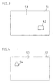
- FIG. the display 51 of the display unit 5 is shown.
- the overview image 53 is shown, in which a frame 52 is displayed, which displays the current viewing direction and the current zoom setting of the PTZ camera. Of the Frame thus displays the field of view currently captured by the camera.
- the insertion of the mark in the overview image can be triggered by means of the input unit 7, which is connected to the display unit 5 via the control unit 6.
- this can be done by marking the desired other location in the overview image by means of the operating unit 7 and then raising a new frame of desired size at this point.
- This can also be done by means of a mouse by the desired other point in the overview image is marked by a first mouse click, then while holding down the mouse button around this point a frame of desired size mounted and set by releasing the mouse button.
- the technical basis for such precise control of the PTZ camera using an overview image is the knowledge of the geometric relationship between the possible positions in the overview image and the pan, tilt and zoom setting of the PTZ camera and the positions in their own image at the Pan, tilt and zoom settings of the PTZ camera.
- the absolute spatial direction is given for a given pixel in the image of the PTZ camera, and vice versa.
- the method according to the invention can be carried out.
- the corresponding pixels edge points, corner points, center of the image and / or zoom center
- the corresponding pixels are first converted to absolute spatial directions and then projected into the overview image with the second instructions given above, in accordance with the first instructions given above ,
- a given position in the overview image is first converted into an absolute spatial direction by means of the second instructions.
- the pan and tilt values can then be determined which make this point the new center of the image.
- the frame of the current field of view can be calculated and displayed. If you also want to adjust the zoom setting, for example by dragging the mouse, you can virtually change the zoom setting by dragging the mouse and the corresponding frame can be displayed. If the section indicated by the frame appears suitable, for example, by releasing the Actually, move the camera to this setting.
- the change of the virtual zoom can take place such that the new opening angle corresponds to the angle between the absolute spatial directions of the new center and the current mouse position during the drawing.
- the displayed frame then has on the one hand the correct geometric shape of a partial image and on the other hand approximately goes through the current mouse position.
- FIG. 2 shows a block diagram for explaining a second embodiment of the invention.
- This second exemplary embodiment differs from the exemplary embodiment illustrated in FIG. 1 in that the individual partial images from which the overview image is composed are not produced by the PTZ camera 1 but by another camera 10. Alternatively, several other cameras can be used to create the partial images that make up the overview image.
- the other cameras are therefore located at substantially the same location relative to the distances of the objects in the scene. In this way, the exact object distances when creating the overview image can be disregarded and unknown.
- a focus value is stored in the focus data memory 8 for each pixel of the overview image in both aforementioned embodiments.
- This focus value is retrieved from the focus data memory 8 when approaching an associated position of the PTZ camera by the control unit 6 and taken into account in the determination of the control signals for the PTZ camera.
- the focus value corresponds to the previously determined object distance at this position.
- An advantageous development of the invention is to specify in the overview image private area, so that the current image content of these areas in the live image of the PTZ camera is not or only partially visible.
- these private areas in the live image of the PTZ camera can be blacked out or out of focus.
- FIG. 1 An example of such a private area is illustrated in FIG. There, the overview image 53 is displayed on the display 51.
- the reference numeral 54 denotes a private area which has been predetermined by the operator by means of the operating unit 7.
- control unit 6 can easily determine even if a large number of private areas whether and where the current field of view of the PTZ camera overlaps with one of these private areas. In the case of such an overlap, alternatively, as indicated above, only the overlapping areas or the entire image may be blackened or out of focus. Alternatively, a setting of large zoom values can also be denied with respect to these areas, ie. H. the camera does not zoom in on this area.
- Motion detectors have settings that specify areas of surveillance, permissible and impermissible directions of movement and image perspectives (the size of persons in front and behind the image).
- a problem with the use of motion detectors in connection with known PTZ cameras is that the mentioned settings relate only to a specific position of the PTZ camera. Consequently, different positions of the PTZ camera also require different settings. This is with associated with a high expenditure of time. Motion detection is not possible for unadjusted positions of the PTZ camera.
- the control according to the invention now makes it possible to specify the monitoring areas and directions, etc., in the overview image.
- Data regarding the perspective can be taken from the above-mentioned focus data memory 8, in which a kind of focus map is stored.
- a motion detection can be performed because the control unit for each position, the sizes of the overview image in the current image of the PTZ camera can convert.
- a further embodiment variant is to view the instantaneous live image of the PTZ camera as an overview image. If the mouse is clicked into this picture and a frame of the desired size is drawn, pan, tilt and zoom of the PTZ camera are adjusted by the control unit 6 in such a way that the frame defined by the frame is displayed as a complete picture. This corresponds to a mouse zoom tracking.
Landscapes
- Engineering & Computer Science (AREA)
- Multimedia (AREA)
- Signal Processing (AREA)
- Human Computer Interaction (AREA)
- Physics & Mathematics (AREA)
- General Physics & Mathematics (AREA)
- Studio Devices (AREA)
- Indication In Cameras, And Counting Of Exposures (AREA)
- Closed-Circuit Television Systems (AREA)
Applications Claiming Priority (1)
| Application Number | Priority Date | Filing Date | Title |
|---|---|---|---|
| DE102006048006A DE102006048006A1 (de) | 2006-10-09 | 2006-10-09 | Verfahren und Vorrichtung zur Steuerung einer schwenkbaren Kamera |
Publications (2)
| Publication Number | Publication Date |
|---|---|
| EP1912431A2 true EP1912431A2 (fr) | 2008-04-16 |
| EP1912431A3 EP1912431A3 (fr) | 2010-07-07 |
Family
ID=38973145
Family Applications (1)
| Application Number | Title | Priority Date | Filing Date |
|---|---|---|---|
| EP07117457A Withdrawn EP1912431A3 (fr) | 2006-10-09 | 2007-09-28 | Procédé et dispositif destinés à la commande d'une caméra pivotante |
Country Status (2)
| Country | Link |
|---|---|
| EP (1) | EP1912431A3 (fr) |
| DE (1) | DE102006048006A1 (fr) |
Cited By (4)
| Publication number | Priority date | Publication date | Assignee | Title |
|---|---|---|---|---|
| WO2018120012A1 (fr) * | 2016-12-30 | 2018-07-05 | 深圳市大疆灵眸科技有限公司 | Procédé et dispositif de commande de tête de berceau, et tête de berceau |
| WO2020062298A1 (fr) * | 2018-09-30 | 2020-04-02 | 深圳市大疆创新科技有限公司 | Cardan et son procédé de commande, et plateforme mobile |
| CN113169630A (zh) * | 2020-10-27 | 2021-07-23 | 深圳市大疆创新科技有限公司 | 跟焦轮的控制方法、跟焦轮及存储介质 |
| WO2022261907A1 (fr) * | 2021-06-17 | 2022-12-22 | 深圳市大疆创新科技有限公司 | Procédé de commande d'un dispositif de suivi de point, ainsi que dispositif et support d'enregistrement |
Family Cites Families (7)
| Publication number | Priority date | Publication date | Assignee | Title |
|---|---|---|---|---|
| DE4233137C1 (de) * | 1992-10-02 | 1994-01-05 | Ibm | Verfahren und Vorrichtung zur Steuerung einer Kamera |
| US6266085B1 (en) * | 1994-11-17 | 2001-07-24 | Canon Kabushiki Kaisha | Camera imaging and magnification device |
| JP4332231B2 (ja) * | 1997-04-21 | 2009-09-16 | ソニー株式会社 | 撮像装置コントローラおよび撮像システム |
| DE10158990C1 (de) * | 2001-11-30 | 2003-04-10 | Bosch Gmbh Robert | Videoüberwachungssystem |
| JP3925299B2 (ja) * | 2002-05-15 | 2007-06-06 | ソニー株式会社 | モニタリングシステムおよび方法 |
| EP1455525A1 (fr) * | 2003-03-05 | 2004-09-08 | TELCAST Media Group GmbH | Procédé et dispositif d'enregistrement des données vidéo |
| US7940302B2 (en) * | 2004-09-15 | 2011-05-10 | The Regents Of The University Of California | Apparatus and method for privacy protection of data collection in pervasive environments |
-
2006
- 2006-10-09 DE DE102006048006A patent/DE102006048006A1/de not_active Withdrawn
-
2007
- 2007-09-28 EP EP07117457A patent/EP1912431A3/fr not_active Withdrawn
Cited By (9)
| Publication number | Priority date | Publication date | Assignee | Title |
|---|---|---|---|---|
| WO2018120012A1 (fr) * | 2016-12-30 | 2018-07-05 | 深圳市大疆灵眸科技有限公司 | Procédé et dispositif de commande de tête de berceau, et tête de berceau |
| US11086202B2 (en) | 2016-12-30 | 2021-08-10 | Sz Dji Osmo Technology Co., Ltd. | Gimbal control method, device, and gimbal |
| US11852958B2 (en) | 2016-12-30 | 2023-12-26 | Sz Dji Osmo Technology Co., Ltd. | Gimbal control method, device, and gimbal |
| US12416849B2 (en) | 2016-12-30 | 2025-09-16 | Sz Dji Osmo Technology Co., Ltd. | Gimbal control method, device, and gimbal |
| WO2020062298A1 (fr) * | 2018-09-30 | 2020-04-02 | 深圳市大疆创新科技有限公司 | Cardan et son procédé de commande, et plateforme mobile |
| CN113169630A (zh) * | 2020-10-27 | 2021-07-23 | 深圳市大疆创新科技有限公司 | 跟焦轮的控制方法、跟焦轮及存储介质 |
| WO2022087828A1 (fr) * | 2020-10-27 | 2022-05-05 | 深圳市大疆创新科技有限公司 | Procédé de commande de roue de suivi de mise au point, roue de suivi de mise au point et support de stockage |
| CN113169630B (zh) * | 2020-10-27 | 2022-07-19 | 深圳市大疆创新科技有限公司 | 跟焦轮的控制方法、跟焦轮及存储介质 |
| WO2022261907A1 (fr) * | 2021-06-17 | 2022-12-22 | 深圳市大疆创新科技有限公司 | Procédé de commande d'un dispositif de suivi de point, ainsi que dispositif et support d'enregistrement |
Also Published As
| Publication number | Publication date |
|---|---|
| EP1912431A3 (fr) | 2010-07-07 |
| DE102006048006A1 (de) | 2008-04-10 |
Similar Documents
| Publication | Publication Date | Title |
|---|---|---|
| DE69429028T2 (de) | Rundumsicht Überwachungssystem mit bewegungsloser Kamera | |
| EP2464098B1 (fr) | Dispositif de représentation d'environnement ainsi qu'un véhicule doté d'un tel dispositif de représentation d'environnement et procédé de représentation d'une image panoramique | |
| DE19825302B4 (de) | System zur Einrichtung einer dreidimensionalen Abfallmatte, welche eine vereinfachte Einstellung räumlicher Beziehungen zwischen realen und virtuellen Szeneelementen ermöglicht | |
| DE69232663T2 (de) | Rundumsichtausrichtungssystem mit bewegungsloser kamera | |
| DE69230512T2 (de) | Modelierungsprozess für Bildaufnahmesystem und Verfahren und System zur Kombinierung von echten Bildern und Synthesebildern | |
| DE69607631T2 (de) | Methode und verfahren zum automatischen und elektronischen einfügen von reklameschildern in einem videobild | |
| EP2880853B1 (fr) | Dispositif et procédé destinés à déterminer la situation d'une caméra de prise de vue | |
| EP3427474B1 (fr) | Procédé de traitement d'images, moyen de traitement d'images et dispositif de traitement d'images pour générer des reproductions d'une partie d'un espace tridimensionnel | |
| EP3857303B1 (fr) | Procédé de réglage de mise au point d'une caméra | |
| EP1912431A2 (fr) | Procédé et dispositif destinés à la commande d'une caméra pivotante | |
| WO2018133996A1 (fr) | Procédé permettant de combiner une pluralité d'images caméra | |
| AT527033B1 (de) | Verfahren zur Darstellung und Aktualisierung eines Panoramabildes einer Landschaft | |
| DE69721520T2 (de) | System mit einem Photosensor, insbesonder zur Zeitmessung bei Wettkämpfen, und Einstellverfahren zum Ausrichten eines solchen Systems auf eine Ziellinie | |
| EP0976003A1 (fr) | Systeme d'imagerie optique et interface utilisateur graphique | |
| EP2884746A1 (fr) | Dispositif de caméra de surveillance doté d'une détermination d'information sur le relief | |
| DE19825837B4 (de) | Verfahren und Vorrichtung zur Steuerung von Lichtstellanlagen | |
| EP1434184B1 (fr) | Commande d'un système multicaméra | |
| DE102006036769B3 (de) | Einrichtung insbesondere zum Echtzeit-Luftbild-Überwachen aus Flugzeugen | |
| DE60108918T2 (de) | Interaktives Verfahren und Vorrichtung für Bildrundfunk einer beweglichen Videokamera | |
| WO2004082266A1 (fr) | Procede et dispositif pour l'enregistrement de donnees video | |
| DE102014105011B4 (de) | System zur Visualisierung des Sichtfeldes einer optischen Vorrichtung | |
| DE102010026572A1 (de) | Verfahren und Einrichtung zur Aufnahme und Wiedergabe von Panoramadarstellungen | |
| EP1296213A1 (fr) | Procédé et dispositif pour guider un véhicule volant sans pilote | |
| WO2001027694A1 (fr) | Dispositif pour projeter des informations sur une surface inclinee | |
| DE102024201794A1 (de) | Kamerasystem zur Leistungssteigerung eines Wahrnehmungssystems |
Legal Events
| Date | Code | Title | Description |
|---|---|---|---|
| PUAI | Public reference made under article 153(3) epc to a published international application that has entered the european phase |
Free format text: ORIGINAL CODE: 0009012 |
|
| AK | Designated contracting states |
Kind code of ref document: A2 Designated state(s): AT BE BG CH CY CZ DE DK EE ES FI FR GB GR HU IE IS IT LI LT LU LV MC MT NL PL PT RO SE SI SK TR |
|
| AX | Request for extension of the european patent |
Extension state: AL BA HR MK RS |
|
| PUAL | Search report despatched |
Free format text: ORIGINAL CODE: 0009013 |
|
| AK | Designated contracting states |
Kind code of ref document: A3 Designated state(s): AT BE BG CH CY CZ DE DK EE ES FI FR GB GR HU IE IS IT LI LT LU LV MC MT NL PL PT RO SE SI SK TR |
|
| AX | Request for extension of the european patent |
Extension state: AL BA HR MK RS |
|
| AKY | No designation fees paid | ||
| STAA | Information on the status of an ep patent application or granted ep patent |
Free format text: STATUS: THE APPLICATION IS DEEMED TO BE WITHDRAWN |
|
| 18D | Application deemed to be withdrawn |
Effective date: 20110108 |