EP1913918A2 - Dispositif d'assistance pour s'asseoir pour personnes âgées et handicapées - Google Patents
Dispositif d'assistance pour s'asseoir pour personnes âgées et handicapées Download PDFInfo
- Publication number
- EP1913918A2 EP1913918A2 EP07118748A EP07118748A EP1913918A2 EP 1913918 A2 EP1913918 A2 EP 1913918A2 EP 07118748 A EP07118748 A EP 07118748A EP 07118748 A EP07118748 A EP 07118748A EP 1913918 A2 EP1913918 A2 EP 1913918A2
- Authority
- EP
- European Patent Office
- Prior art keywords
- seat
- base
- arm
- front side
- arms
- Prior art date
- Legal status (The legal status is an assumption and is not a legal conclusion. Google has not performed a legal analysis and makes no representation as to the accuracy of the status listed.)
- Granted
Links
- 230000009471 action Effects 0.000 claims description 9
- 238000004804 winding Methods 0.000 claims description 2
- 230000007246 mechanism Effects 0.000 description 9
- 238000013519 translation Methods 0.000 description 9
- 230000000630 rising effect Effects 0.000 description 5
- 208000027418 Wounds and injury Diseases 0.000 description 3
- 230000006378 damage Effects 0.000 description 3
- 208000014674 injury Diseases 0.000 description 3
- 208000018883 loss of balance Diseases 0.000 description 3
- 210000003141 lower extremity Anatomy 0.000 description 3
- 230000008901 benefit Effects 0.000 description 2
- 210000000988 bone and bone Anatomy 0.000 description 2
- 210000004705 lumbosacral region Anatomy 0.000 description 2
- 238000012423 maintenance Methods 0.000 description 2
- 238000004519 manufacturing process Methods 0.000 description 2
- 210000003205 muscle Anatomy 0.000 description 2
- 229910000831 Steel Inorganic materials 0.000 description 1
- 230000032683 aging Effects 0.000 description 1
- 238000013459 approach Methods 0.000 description 1
- 230000008859 change Effects 0.000 description 1
- 230000008602 contraction Effects 0.000 description 1
- 230000008878 coupling Effects 0.000 description 1
- 238000010168 coupling process Methods 0.000 description 1
- 238000005859 coupling reaction Methods 0.000 description 1
- 230000003412 degenerative effect Effects 0.000 description 1
- 238000006073 displacement reaction Methods 0.000 description 1
- 230000003028 elevating effect Effects 0.000 description 1
- 230000014509 gene expression Effects 0.000 description 1
- 210000003127 knee Anatomy 0.000 description 1
- 206010025482 malaise Diseases 0.000 description 1
- 239000000463 material Substances 0.000 description 1
- 238000012986 modification Methods 0.000 description 1
- 230000004048 modification Effects 0.000 description 1
- 230000003387 muscular Effects 0.000 description 1
- 230000007170 pathology Effects 0.000 description 1
- 230000000284 resting effect Effects 0.000 description 1
- 239000010959 steel Substances 0.000 description 1
Images


Classifications
-
- A—HUMAN NECESSITIES
- A61—MEDICAL OR VETERINARY SCIENCE; HYGIENE
- A61G—TRANSPORT, PERSONAL CONVEYANCES, OR ACCOMMODATION SPECIALLY ADAPTED FOR PATIENTS OR DISABLED PERSONS; OPERATING TABLES OR CHAIRS; CHAIRS FOR DENTISTRY; FUNERAL DEVICES
- A61G5/00—Chairs or personal conveyances specially adapted for patients or disabled persons, e.g. wheelchairs
- A61G5/10—Parts, details or accessories
- A61G5/14—Standing-up or sitting-down aids
Definitions
- the present invention relates to the field of domestic mobility aiding devices destined for persons with reduced mobility, such as those with physical disabilities caused by sickness, injury or simply by the age. More particularly, the invention relates to a new device destined for seat assistance, i.e. for aiding the person to stand starting from a seated position.
- the motion involved in lifting the barycentre of a seated person when attempting to stand erect is comprised of two main components: a translation in a forward direction associated to a translation in an upward direction.
- a translation in a forward direction associated to a translation in an upward direction.
- the aforesaid motion involves the participation of a large portion of the bone and muscle structure, in both the lower limbs as well as the medium to lower part of the trunk. After an injury or because of degenerative phenomena due to some pathology or simply because of physiological reasons such as the aging process, it can happen that the person loses considerable mobility functions to the point that even a normally simple movement such as getting up from a chair or an armchair becomes impossible or at the least, extremely difficult.
- prior art provides for armchairs, chairs or seats (including some for use on WC toilet seats or other bathroom facilities) which use motorized mechanisms of various kinds that are able to rise up in a controlled manner, inclining and elevating the seating plane, in such a manner that the lumbar region and back of the person is lifted and pushed forward to permit the change from a seated to an erect position with far less effort.
- the reverse movement permits to support and assist the return to a seated position, making the motion more gradual and reducing the possibility of injury.
- the solution described above presents a drawback in that it requires a dedicated structure, this meaning that the user is forced to purchase a specific piece of furniture (generally quite expensive) or at least a frame which is rather difficult to move from one particular position. Moreover, the user is forced to use always and exclusively that same piece or frame if he wants to take advantage of the rising aid functionality. Additionally, the size and weight of the structure to be moved also imposes the use of motorised lifting mechanisms that are complex and costly in relation to both production as well as maintenance.
- Both these devices have a structure with a base which is positioned on the seat of the chair or armchair, and a shell that is articulated in relation to the base.
- the convex surface of the shell acts as a new (mobile) seat.
- the articulation of the shell in relation to the base is driven and controlled by a motorized mechanism positioned between the two elements. When in closed position, i.e. when the seating surface is in a substantially horizontal position, the mechanism is housed inside the cavity defined by the convex surface of the shell.
- the seating surface simply rotates around an axis that extends along the front side of the seat, in other words, the side adjacent to the knees of the sitting user.
- This is not totally satisfactory in relation to the need of assisting the natural rising motion in the best possible manner, because, as described above, this motion is composed of a combined forward translation movement with an upward translation of the body.
- the user is lifted by means of a simple rotation of his barycentre; further to said rotation, the barycentre becomes displaced backwards with respect to the vertical line conducted from the user's feet. This involves an additional muscular effort which is considerable, and which can also lead to dangerous loss of balance.
- the object of the present invention is to provide a cushion similar to that described above, but wherein the motion of the seating surface is more similar to that naturally performed by the human body when rising to an erect position, and therefore is able to assist the user in a more efficient manner, requiring less effort and minimizing the risk of loss of balance during the lifting action.
- a further object of the present invention is to provide a cushion of the aforementioned type, wherein the motion of the seat surface is driven by a mechanism having a basic structure and simple operation.
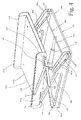
- a device comprises a base 1 composed, in this example, of a plate-shaped body defining a resting surface 1 on the underside for being positioned in a horizontal position on the surface of the seat of a conventional chair or armchair (not illustrated).
- the device comprises a mobile seat 2, in this example, having a disk-like shape of a size that substantially corresponds to that of the base 1, and defining on the upper side a substantially plane seat surface 2a.
- the seat 2 is connected to the base 1 so as to be movable between a closed configuration (figure 1), wherein the two bodies are adjacent to one another, and an open configuration (figure 2), wherein the seat 2 is displaced both in an orthogonal direction in relation to the base 1, and in a parallel direction with respect to said base towards the front side.
- This latter side is the one resulting in front, from the point of view of a user sitting on the seat 2, identified at the numeral 1a on the base 1 and at the numeral 2b on the same seat.
- the seat 2 is set at an angle in relation to the horizontal plane, sloping towards the front side 2b.
- a mechanism 3 comprising a couple of articulations 4 arranged among the lateral sides, indicated respectively at the numerals 1b and 2c for base 1 and seat 2, positioned on each flank of the user when sitting.
- Each articulation 4 comprises two crossed arms 5, 6, mutually hinged in the point of contact by a pivot 7, set in a substantially central position in relation to the lengthwise direction of the arms.
- a first arm 5 is pivotally connected at respective ends to base 1, in proximity to the front side 1a, and to the seat 2, in proximity to the rear side identified by numeral 2d, by means of pivots 8, 9.
- a second arm 6 is arranged in the opposite way, extending between the rear part of base 1 and the front side of seat 2.
- connection of the end of the arm with the base and the seat is carried out by means of roto-translation couplings comprising sliders 10, 11 projecting from arm 6 and slidingly engaged in respective guides 12, 13 set respectively along the lateral sides of base 1 and seat 2.
- Drive means arranged between the two bodies and acting directly on the bodies or on mechanism 3, are provided to control the motion between the two configurations.
- Said means can comprise a mechanical or pneumatic actuator, an air spring, an inflatable device or the like, as will be discussed further on.
- the relative propulsion means have not been illustrated for the same reason, but these will comprise suitable electric motor means and relative batteries.
- the geometry of the two articulations 4 and the kinematics of the relative connections is conceived to ensure a very compact closed configuration, with the seat 2 which approaches and is set on top of the base 1; in this configuration the sliders 10, 11 of the second arm move to the ends of their runs, respectively to the rear and front of the guides 12, 13.
- the seat 2 elevates and moves forward slightly sloping, to assist the lumbar region of the user in a movement that is truly similar to the natural rising movement.
- Said adjustments can also be obtained by using arms 6, 7 having a telescopic structure, or in any case arms that can be adjusted in length, in a discrete manner for pre-established lengths as well as continuously (such as with snap engagement systems or a threaded rod with a nut and counter nut).
- the tie rod 115 links the translation of the seat 2 with the rotation of the first arm 105, preventing a free horizontal sliding on the guides 109, 113.
- a further variant can provide for the replacement of the tie rod 115 with a guide cam which, on seat 102, acts as a guiding element for a slider attached to the second arm 106.
- a guide cam which, on seat 102, acts as a guiding element for a slider attached to the second arm 106.
- by adjusting the length of the linear elements (arms and tie rods) it is possible to adapt various functional parameters according to personal requirements: lifting height, forward displacement of the seat, and rotation angle of the same.
- the embodiment shown in figure 4 shows that the guides 112 along the lateral sides 101b of the base 101 are specifically outlined, in particular, with a segment 112a that rises on a slope in an upward direction.
- This specific shape, or other similar forms, can be used in turn to control the various movements of the seat 2 in different ways.
- This figure also shows with more precision, and purely as an example, certain constructive solutions that could be adopted as alternatives.
- the guides 112 are each realised on a double ridge 101c rising along one lateral side 101b of a basic flat rectangular element that forms the main body of the base 101.
- the second arms 106 have a structure with two parallel rods 106a, inside which the first arms 105 and, in this case, also the tie rods 115, are inserted at the crossing points.
- the seat 102 comprises a sliding seat surface 102a, which can travel back and forward, with a certain degree of resistance, in relation to the underlying structure on which the drive mechanism 103 is connected. In this manner, a further possibility is made available to adapt the position for the user.
- the figure shows the drive means, in the form of a pneumatic jack 118 hinged at one end to the base plate 101, in a central position, and, at the other end, connected to a rod 119 that joins the two sliders 111 transversally at the lower ends of the second arms 106, being pivotable with respect to said arms.
- the retraction of the jack 118 corresponds to a pulling action on rod 119 in a frontal direction, resulting in the elevation of the seat 2 to the open configuration.
- the jack 118 is extended, the seat reverts to the closed configuration.
- the actuator is connected to a pneumatic circuit controlled by an electric pump, or alternatively, manually operated.
- the operating means are composed of a rear pantograph 120 that extends between the base 101 and the seat 102 in such a manner that it commands the lifting and lowering of said seat by means of its own closing/opening movement.
- the movement performed by the pantograph 120 is, in fact, controlled by a worm screw system (not illustrated) which works in correspondence to the connection to the base 101.
- the rotation of the screw driven by a motor, causes the mutual contraction or extension movement of the two lower ends of the pantograph, and in a consequential manner, also of the two upper ends attached to the seat 102 by means of hinges 121 and a prismatic guide 122.
- a wom screw system can also be used to act directly on one or both sliders 111 at the lower end of the second arms 106.
- a further alternative can also be the use of an inflatable cushion which, when inserted between the base and seat, through the inflation, generates the upward thrust action necessary to lift and support the seat while the user is still seated. Because of the kinematics described above, this thrust action will result in the various motion components of the seat. A small electric or manually operated pump is sufficient to inflate the air cushion.
- other purely mechanical means can be applied, such as a system using steel wires that pull the rod 119 (figure 4) from opposite directions and in a coordinated manner, controlled by motorized winding means.
- the invention therefore provides for a seat assist device for disabled persons, or more generally, for those who have problems with lower limbs, wherein the seat is equipped with an elevation system that permits the user to perform a movement that is very close to a natural movement.
- the barycentre of the person follows a course that prevents loss of balance during the lifting action, protecting the bone-muscular structure from excessive overloading caused by unnatural movement, and, at the same time, reducing the force that is necessary to the lifting action.
- This result is achieved with extremely simple mechanical solutions, and therefore also with low production and maintenance costs, as well as with no drawbacks in relation to bulk and weight.
- the device has a size and compactness that make it possible and simple to install it on the seat of any type of chair or armchair, or as a replacement for an existing cushion.
- the seat surface 2a on seat 2 can consist of an actual material plane surface, as shown in the example, or an imaginary plane as a result of a linear interpolation or of an envelope plane of a concave or generally undulated surface, and that represents the support with which said surface is schematically representable.
Landscapes
- Health & Medical Sciences (AREA)
- Life Sciences & Earth Sciences (AREA)
- Animal Behavior & Ethology (AREA)
- General Health & Medical Sciences (AREA)
- Public Health (AREA)
- Veterinary Medicine (AREA)
- Chair Legs, Seat Parts, And Backrests (AREA)
- Invalid Beds And Related Equipment (AREA)
- Rehabilitation Tools (AREA)
- Chairs For Special Purposes, Such As Reclining Chairs (AREA)
Applications Claiming Priority (1)
| Application Number | Priority Date | Filing Date | Title |
|---|---|---|---|
| IT000253A ITFI20060253A1 (it) | 2006-10-18 | 2006-10-18 | Dispositivo di ausilio all'elevazione per anziani e disabili |
Publications (3)
| Publication Number | Publication Date |
|---|---|
| EP1913918A2 true EP1913918A2 (fr) | 2008-04-23 |
| EP1913918A3 EP1913918A3 (fr) | 2008-11-26 |
| EP1913918B1 EP1913918B1 (fr) | 2011-02-16 |
Family
ID=38962735
Family Applications (1)
| Application Number | Title | Priority Date | Filing Date |
|---|---|---|---|
| EP07118748A Not-in-force EP1913918B1 (fr) | 2006-10-18 | 2007-10-18 | Dispositif d'assistance pour s'asseoir pour personnes âgées et handicapées |
Country Status (4)
| Country | Link |
|---|---|
| EP (1) | EP1913918B1 (fr) |
| AT (1) | ATE498382T1 (fr) |
| DE (1) | DE602007012498D1 (fr) |
| IT (1) | ITFI20060253A1 (fr) |
Cited By (5)
| Publication number | Priority date | Publication date | Assignee | Title |
|---|---|---|---|---|
| FR2952613A1 (fr) * | 2009-11-17 | 2011-05-20 | Sicma Aero Seat | Ensemble permettant le transfert d'un passager handicape dans un avion et procede de transfert de passager handicape associe |
| DE102010025712A1 (de) * | 2010-06-30 | 2012-01-05 | Wilhelm Schulte-Derne Gmbh | Rahmen für einen Rollstuhl |
| KR101919837B1 (ko) | 2017-07-18 | 2018-11-19 | 주식회사 크리벤 | 전동식 자전거 안장 각도조절장치 |
| CN110522574A (zh) * | 2019-09-05 | 2019-12-03 | 张铸 | 智能辅助站立装置及控制方法 |
| CN110742546A (zh) * | 2019-11-25 | 2020-02-04 | 郑州轻工业大学 | 带有辅助站立作用蹲便改坐便的装置 |
Families Citing this family (1)
| Publication number | Priority date | Publication date | Assignee | Title |
|---|---|---|---|---|
| IT202100030476A1 (it) | 2021-12-02 | 2022-03-02 | Francesco Dadone | Sistema di movimentazione di una base di supporto per barella |
Citations (1)
| Publication number | Priority date | Publication date | Assignee | Title |
|---|---|---|---|---|
| DE4408458A1 (de) | 1994-03-12 | 1995-09-14 | Klaus Peter Dipl Ing Flamme | Anordnung einer Universalmechanik aus Aluminiumgußteilen zum Verändern der Teilepositionen von Sitzmöbeln zum Zwecke der Ruhestellung und Aufstehhilfe |
Family Cites Families (5)
| Publication number | Priority date | Publication date | Assignee | Title |
|---|---|---|---|---|
| GB2191683A (en) * | 1986-05-28 | 1987-12-23 | John Alfred Hooker | Seat unit |
| US5918936A (en) * | 1997-02-14 | 1999-07-06 | Murphy; Lloyd F. | Seat lift mechanism |
| US6113188A (en) * | 1997-12-24 | 2000-09-05 | Stewart; Robert V. | Portable seating assist device |
| DE29808584U1 (de) * | 1998-05-13 | 1998-10-22 | Mühlberger, Dieter, Dipl.-Designer (FH), 55546 Frei-Laubersheim | Mechanik zur Anhebung und anschließender Sitzkippung (Aufstehhilfe) eines Sitzes oder Sessels |
| GB9928001D0 (en) * | 1999-11-27 | 2000-01-26 | Easy Care Prod Ltd | Body support system for patients and the like |
-
2006
- 2006-10-18 IT IT000253A patent/ITFI20060253A1/it unknown
-
2007
- 2007-10-18 EP EP07118748A patent/EP1913918B1/fr not_active Not-in-force
- 2007-10-18 AT AT07118748T patent/ATE498382T1/de not_active IP Right Cessation
- 2007-10-18 DE DE602007012498T patent/DE602007012498D1/de active Active
Patent Citations (1)
| Publication number | Priority date | Publication date | Assignee | Title |
|---|---|---|---|---|
| DE4408458A1 (de) | 1994-03-12 | 1995-09-14 | Klaus Peter Dipl Ing Flamme | Anordnung einer Universalmechanik aus Aluminiumgußteilen zum Verändern der Teilepositionen von Sitzmöbeln zum Zwecke der Ruhestellung und Aufstehhilfe |
Cited By (7)
| Publication number | Priority date | Publication date | Assignee | Title |
|---|---|---|---|---|
| FR2952613A1 (fr) * | 2009-11-17 | 2011-05-20 | Sicma Aero Seat | Ensemble permettant le transfert d'un passager handicape dans un avion et procede de transfert de passager handicape associe |
| DE102010025712A1 (de) * | 2010-06-30 | 2012-01-05 | Wilhelm Schulte-Derne Gmbh | Rahmen für einen Rollstuhl |
| DE102010025712B4 (de) * | 2010-06-30 | 2013-12-12 | Wilhelm Schulte-Derne Gmbh | Rahmen für einen Rollstuhl |
| KR101919837B1 (ko) | 2017-07-18 | 2018-11-19 | 주식회사 크리벤 | 전동식 자전거 안장 각도조절장치 |
| CN110522574A (zh) * | 2019-09-05 | 2019-12-03 | 张铸 | 智能辅助站立装置及控制方法 |
| CN110522574B (zh) * | 2019-09-05 | 2024-05-31 | 张铸 | 智能辅助站立装置及控制方法 |
| CN110742546A (zh) * | 2019-11-25 | 2020-02-04 | 郑州轻工业大学 | 带有辅助站立作用蹲便改坐便的装置 |
Also Published As
| Publication number | Publication date |
|---|---|
| DE602007012498D1 (de) | 2011-03-31 |
| ITFI20060253A1 (it) | 2008-04-19 |
| EP1913918B1 (fr) | 2011-02-16 |
| EP1913918A3 (fr) | 2008-11-26 |
| ATE498382T1 (de) | 2011-03-15 |
Similar Documents
| Publication | Publication Date | Title |
|---|---|---|
| US5870784A (en) | Adjustable articulated bed | |
| US4386803A (en) | Motorized reclining chair | |
| US5098158A (en) | Articulated relaxation chair | |
| US3479086A (en) | Chair for physically handicapped persons | |
| US5131717A (en) | Reclining chair having a movable seat back and a movable seat bottom | |
| US6000758A (en) | Reclining lift chair | |
| US6382725B1 (en) | Examination chair with lifting and tilting mechanism | |
| US5730494A (en) | Linear actuation drive mechanism for power-assisted chairs | |
| US4966413A (en) | Articulated relaxation chair | |
| CN100353890C (zh) | 用于调整床、床垫及躺椅的装置以及可调整的支承装置 | |
| EP1913918B1 (fr) | Dispositif d'assistance pour s'asseoir pour personnes âgées et handicapées | |
| US5094508A (en) | Elevator chair | |
| US20150164719A1 (en) | Seat structure with sit-to-stand feature | |
| WO1988007944A1 (fr) | Fauteuil roulant a dossier reglable | |
| WO2014015130A1 (fr) | Ensemble élévateur d'assise | |
| US4535492A (en) | Pillow bed mechanism | |
| CN112155870A (zh) | 一种可以控制座椅高度和躺卧休息的轮椅 | |
| US6003168A (en) | Person movement apparatus | |
| KR20110029699A (ko) | 기립보조의자 | |
| JP2010131249A (ja) | 足揉み装置を備えたマッサージ椅子 | |
| JP2606353Y2 (ja) | リフトアップチェア | |
| CN100438804C (zh) | 可调整的躺椅或床 | |
| CN210383359U (zh) | 一种美容床多位可调结构 | |
| CN116019677A (zh) | 一种坐躺可调支架及按摩椅架 | |
| GB2161371A (en) | A raisable and lowerable chair to aid standing and sitting |
Legal Events
| Date | Code | Title | Description |
|---|---|---|---|
| PUAI | Public reference made under article 153(3) epc to a published international application that has entered the european phase |
Free format text: ORIGINAL CODE: 0009012 |
|
| AK | Designated contracting states |
Kind code of ref document: A2 Designated state(s): AT BE BG CH CY CZ DE DK EE ES FI FR GB GR HU IE IS IT LI LT LU LV MC MT NL PL PT RO SE SI SK TR |
|
| AX | Request for extension of the european patent |
Extension state: AL BA HR MK RS |
|
| PUAL | Search report despatched |
Free format text: ORIGINAL CODE: 0009013 |
|
| AK | Designated contracting states |
Kind code of ref document: A3 Designated state(s): AT BE BG CH CY CZ DE DK EE ES FI FR GB GR HU IE IS IT LI LT LU LV MC MT NL PL PT RO SE SI SK TR |
|
| AX | Request for extension of the european patent |
Extension state: AL BA HR MK RS |
|
| 17P | Request for examination filed |
Effective date: 20090219 |
|
| 17Q | First examination report despatched |
Effective date: 20090319 |
|
| AKX | Designation fees paid |
Designated state(s): AT BE BG CH CY CZ DE DK EE ES FI FR GB GR HU IE IS IT LI LT LU LV MC MT NL PL PT RO SE SI SK TR |
|
| GRAP | Despatch of communication of intention to grant a patent |
Free format text: ORIGINAL CODE: EPIDOSNIGR1 |
|
| GRAS | Grant fee paid |
Free format text: ORIGINAL CODE: EPIDOSNIGR3 |
|
| GRAA | (expected) grant |
Free format text: ORIGINAL CODE: 0009210 |
|
| AK | Designated contracting states |
Kind code of ref document: B1 Designated state(s): AT BE BG CH CY CZ DE DK EE ES FI FR GB GR HU IE IS IT LI LT LU LV MC MT NL PL PT RO SE SI SK TR |
|
| REG | Reference to a national code |
Ref country code: GB Ref legal event code: FG4D |
|
| REG | Reference to a national code |
Ref country code: CH Ref legal event code: EP |
|
| REG | Reference to a national code |
Ref country code: IE Ref legal event code: FG4D |
|
| REF | Corresponds to: |
Ref document number: 602007012498 Country of ref document: DE Date of ref document: 20110331 Kind code of ref document: P |
|
| REG | Reference to a national code |
Ref country code: DE Ref legal event code: R096 Ref document number: 602007012498 Country of ref document: DE Effective date: 20110331 |
|
| REG | Reference to a national code |
Ref country code: NL Ref legal event code: VDEP Effective date: 20110216 |
|
| LTIE | Lt: invalidation of european patent or patent extension |
Effective date: 20110216 |
|
| PG25 | Lapsed in a contracting state [announced via postgrant information from national office to epo] |
Ref country code: SE Free format text: LAPSE BECAUSE OF FAILURE TO SUBMIT A TRANSLATION OF THE DESCRIPTION OR TO PAY THE FEE WITHIN THE PRESCRIBED TIME-LIMIT Effective date: 20110216 Ref country code: LT Free format text: LAPSE BECAUSE OF FAILURE TO SUBMIT A TRANSLATION OF THE DESCRIPTION OR TO PAY THE FEE WITHIN THE PRESCRIBED TIME-LIMIT Effective date: 20110216 Ref country code: GR Free format text: LAPSE BECAUSE OF FAILURE TO SUBMIT A TRANSLATION OF THE DESCRIPTION OR TO PAY THE FEE WITHIN THE PRESCRIBED TIME-LIMIT Effective date: 20110517 Ref country code: LV Free format text: LAPSE BECAUSE OF FAILURE TO SUBMIT A TRANSLATION OF THE DESCRIPTION OR TO PAY THE FEE WITHIN THE PRESCRIBED TIME-LIMIT Effective date: 20110216 Ref country code: PT Free format text: LAPSE BECAUSE OF FAILURE TO SUBMIT A TRANSLATION OF THE DESCRIPTION OR TO PAY THE FEE WITHIN THE PRESCRIBED TIME-LIMIT Effective date: 20110616 Ref country code: ES Free format text: LAPSE BECAUSE OF FAILURE TO SUBMIT A TRANSLATION OF THE DESCRIPTION OR TO PAY THE FEE WITHIN THE PRESCRIBED TIME-LIMIT Effective date: 20110527 |
|
| PG25 | Lapsed in a contracting state [announced via postgrant information from national office to epo] |
Ref country code: CY Free format text: LAPSE BECAUSE OF FAILURE TO SUBMIT A TRANSLATION OF THE DESCRIPTION OR TO PAY THE FEE WITHIN THE PRESCRIBED TIME-LIMIT Effective date: 20110216 Ref country code: SI Free format text: LAPSE BECAUSE OF FAILURE TO SUBMIT A TRANSLATION OF THE DESCRIPTION OR TO PAY THE FEE WITHIN THE PRESCRIBED TIME-LIMIT Effective date: 20110216 Ref country code: NL Free format text: LAPSE BECAUSE OF FAILURE TO SUBMIT A TRANSLATION OF THE DESCRIPTION OR TO PAY THE FEE WITHIN THE PRESCRIBED TIME-LIMIT Effective date: 20110216 Ref country code: PL Free format text: LAPSE BECAUSE OF FAILURE TO SUBMIT A TRANSLATION OF THE DESCRIPTION OR TO PAY THE FEE WITHIN THE PRESCRIBED TIME-LIMIT Effective date: 20110216 Ref country code: BG Free format text: LAPSE BECAUSE OF FAILURE TO SUBMIT A TRANSLATION OF THE DESCRIPTION OR TO PAY THE FEE WITHIN THE PRESCRIBED TIME-LIMIT Effective date: 20110516 Ref country code: FI Free format text: LAPSE BECAUSE OF FAILURE TO SUBMIT A TRANSLATION OF THE DESCRIPTION OR TO PAY THE FEE WITHIN THE PRESCRIBED TIME-LIMIT Effective date: 20110216 Ref country code: AT Free format text: LAPSE BECAUSE OF FAILURE TO SUBMIT A TRANSLATION OF THE DESCRIPTION OR TO PAY THE FEE WITHIN THE PRESCRIBED TIME-LIMIT Effective date: 20110216 Ref country code: BE Free format text: LAPSE BECAUSE OF FAILURE TO SUBMIT A TRANSLATION OF THE DESCRIPTION OR TO PAY THE FEE WITHIN THE PRESCRIBED TIME-LIMIT Effective date: 20110216 |
|
| PG25 | Lapsed in a contracting state [announced via postgrant information from national office to epo] |
Ref country code: EE Free format text: LAPSE BECAUSE OF FAILURE TO SUBMIT A TRANSLATION OF THE DESCRIPTION OR TO PAY THE FEE WITHIN THE PRESCRIBED TIME-LIMIT Effective date: 20110216 Ref country code: DK Free format text: LAPSE BECAUSE OF FAILURE TO SUBMIT A TRANSLATION OF THE DESCRIPTION OR TO PAY THE FEE WITHIN THE PRESCRIBED TIME-LIMIT Effective date: 20110216 |
|
| PG25 | Lapsed in a contracting state [announced via postgrant information from national office to epo] |
Ref country code: RO Free format text: LAPSE BECAUSE OF FAILURE TO SUBMIT A TRANSLATION OF THE DESCRIPTION OR TO PAY THE FEE WITHIN THE PRESCRIBED TIME-LIMIT Effective date: 20110216 Ref country code: CZ Free format text: LAPSE BECAUSE OF FAILURE TO SUBMIT A TRANSLATION OF THE DESCRIPTION OR TO PAY THE FEE WITHIN THE PRESCRIBED TIME-LIMIT Effective date: 20110216 Ref country code: SK Free format text: LAPSE BECAUSE OF FAILURE TO SUBMIT A TRANSLATION OF THE DESCRIPTION OR TO PAY THE FEE WITHIN THE PRESCRIBED TIME-LIMIT Effective date: 20110216 |
|
| PLBE | No opposition filed within time limit |
Free format text: ORIGINAL CODE: 0009261 |
|
| STAA | Information on the status of an ep patent application or granted ep patent |
Free format text: STATUS: NO OPPOSITION FILED WITHIN TIME LIMIT |
|
| 26N | No opposition filed |
Effective date: 20111117 |
|
| REG | Reference to a national code |
Ref country code: DE Ref legal event code: R097 Ref document number: 602007012498 Country of ref document: DE Effective date: 20111117 |
|
| PG25 | Lapsed in a contracting state [announced via postgrant information from national office to epo] |
Ref country code: MC Free format text: LAPSE BECAUSE OF NON-PAYMENT OF DUE FEES Effective date: 20111031 |
|
| REG | Reference to a national code |
Ref country code: CH Ref legal event code: PL |
|
| PG25 | Lapsed in a contracting state [announced via postgrant information from national office to epo] |
Ref country code: CH Free format text: LAPSE BECAUSE OF NON-PAYMENT OF DUE FEES Effective date: 20111031 Ref country code: LI Free format text: LAPSE BECAUSE OF NON-PAYMENT OF DUE FEES Effective date: 20111031 |
|
| REG | Reference to a national code |
Ref country code: IE Ref legal event code: MM4A |
|
| PG25 | Lapsed in a contracting state [announced via postgrant information from national office to epo] |
Ref country code: IE Free format text: LAPSE BECAUSE OF NON-PAYMENT OF DUE FEES Effective date: 20111018 |
|
| PG25 | Lapsed in a contracting state [announced via postgrant information from national office to epo] |
Ref country code: MT Free format text: LAPSE BECAUSE OF FAILURE TO SUBMIT A TRANSLATION OF THE DESCRIPTION OR TO PAY THE FEE WITHIN THE PRESCRIBED TIME-LIMIT Effective date: 20110216 |
|
| PG25 | Lapsed in a contracting state [announced via postgrant information from national office to epo] |
Ref country code: LU Free format text: LAPSE BECAUSE OF NON-PAYMENT OF DUE FEES Effective date: 20111018 |
|
| PG25 | Lapsed in a contracting state [announced via postgrant information from national office to epo] |
Ref country code: IS Free format text: LAPSE BECAUSE OF FAILURE TO SUBMIT A TRANSLATION OF THE DESCRIPTION OR TO PAY THE FEE WITHIN THE PRESCRIBED TIME-LIMIT Effective date: 20110216 |
|
| PG25 | Lapsed in a contracting state [announced via postgrant information from national office to epo] |
Ref country code: TR Free format text: LAPSE BECAUSE OF FAILURE TO SUBMIT A TRANSLATION OF THE DESCRIPTION OR TO PAY THE FEE WITHIN THE PRESCRIBED TIME-LIMIT Effective date: 20110216 |
|
| PG25 | Lapsed in a contracting state [announced via postgrant information from national office to epo] |
Ref country code: HU Free format text: LAPSE BECAUSE OF FAILURE TO SUBMIT A TRANSLATION OF THE DESCRIPTION OR TO PAY THE FEE WITHIN THE PRESCRIBED TIME-LIMIT Effective date: 20110216 |
|
| PGFP | Annual fee paid to national office [announced via postgrant information from national office to epo] |
Ref country code: GB Payment date: 20131120 Year of fee payment: 7 Ref country code: DE Payment date: 20131112 Year of fee payment: 7 Ref country code: FR Payment date: 20131031 Year of fee payment: 7 |
|
| PGFP | Annual fee paid to national office [announced via postgrant information from national office to epo] |
Ref country code: IT Payment date: 20131031 Year of fee payment: 7 |
|
| REG | Reference to a national code |
Ref country code: DE Ref legal event code: R119 Ref document number: 602007012498 Country of ref document: DE |
|
| GBPC | Gb: european patent ceased through non-payment of renewal fee |
Effective date: 20141018 |
|
| PG25 | Lapsed in a contracting state [announced via postgrant information from national office to epo] |
Ref country code: DE Free format text: LAPSE BECAUSE OF NON-PAYMENT OF DUE FEES Effective date: 20150501 Ref country code: GB Free format text: LAPSE BECAUSE OF NON-PAYMENT OF DUE FEES Effective date: 20141018 |
|
| REG | Reference to a national code |
Ref country code: FR Ref legal event code: ST Effective date: 20150630 |
|
| PG25 | Lapsed in a contracting state [announced via postgrant information from national office to epo] |
Ref country code: IT Free format text: LAPSE BECAUSE OF NON-PAYMENT OF DUE FEES Effective date: 20141018 Ref country code: FR Free format text: LAPSE BECAUSE OF NON-PAYMENT OF DUE FEES Effective date: 20141031 |