EP1914031A1 - Halter mit Taumeluntersetzung - Google Patents
Halter mit Taumeluntersetzung Download PDFInfo
- Publication number
- EP1914031A1 EP1914031A1 EP07118247A EP07118247A EP1914031A1 EP 1914031 A1 EP1914031 A1 EP 1914031A1 EP 07118247 A EP07118247 A EP 07118247A EP 07118247 A EP07118247 A EP 07118247A EP 1914031 A1 EP1914031 A1 EP 1914031A1
- Authority
- EP
- European Patent Office
- Prior art keywords
- gear
- chuck
- fastener
- housing
- nutating gear
- Prior art date
- Legal status (The legal status is an assumption and is not a legal conclusion. Google has not performed a legal analysis and makes no representation as to the accuracy of the status listed.)
- Granted
Links
- 230000009467 reduction Effects 0.000 title description 29
- 238000010276 construction Methods 0.000 claims description 13
- 238000000034 method Methods 0.000 claims description 4
- 230000003993 interaction Effects 0.000 description 11
- 230000007246 mechanism Effects 0.000 description 8
- 230000008901 benefit Effects 0.000 description 3
- 230000008878 coupling Effects 0.000 description 3
- 238000010168 coupling process Methods 0.000 description 3
- 238000005859 coupling reaction Methods 0.000 description 3
- 230000008569 process Effects 0.000 description 2
- 230000000295 complement effect Effects 0.000 description 1
- 230000014759 maintenance of location Effects 0.000 description 1
- 230000004048 modification Effects 0.000 description 1
- 238000012986 modification Methods 0.000 description 1
Images






Classifications
-
- B—PERFORMING OPERATIONS; TRANSPORTING
- B23—MACHINE TOOLS; METAL-WORKING NOT OTHERWISE PROVIDED FOR
- B23B—TURNING; BORING
- B23B31/00—Chucks; Expansion mandrels; Adaptations thereof for remote control
- B23B31/02—Chucks
- B23B31/10—Chucks characterised by the retaining or gripping devices or their immediate operating means
- B23B31/12—Chucks with simultaneously-acting jaws, whether or not also individually adjustable
- B23B31/1207—Chucks with simultaneously-acting jaws, whether or not also individually adjustable moving obliquely to the axis of the chuck in a plane containing this axis
- B23B31/1253—Jaws movement actuated by an axially movable member
-
- B—PERFORMING OPERATIONS; TRANSPORTING
- B23—MACHINE TOOLS; METAL-WORKING NOT OTHERWISE PROVIDED FOR
- B23B—TURNING; BORING
- B23B31/00—Chucks; Expansion mandrels; Adaptations thereof for remote control
- B23B31/02—Chucks
- B23B31/10—Chucks characterised by the retaining or gripping devices or their immediate operating means
- B23B31/12—Chucks with simultaneously-acting jaws, whether or not also individually adjustable
- B23B31/1207—Chucks with simultaneously-acting jaws, whether or not also individually adjustable moving obliquely to the axis of the chuck in a plane containing this axis
- B23B31/1238—Jaws movement actuated by a nut with conical screw-thread
-
- B—PERFORMING OPERATIONS; TRANSPORTING
- B27—WORKING OR PRESERVING WOOD OR SIMILAR MATERIAL; NAILING OR STAPLING MACHINES IN GENERAL
- B27B—SAWS FOR WOOD OR SIMILAR MATERIAL; COMPONENTS OR ACCESSORIES THEREFOR
- B27B5/00—Sawing machines working with circular or cylindrical saw blades; Components or equipment therefor
- B27B5/29—Details; Component parts; Accessories
- B27B5/30—Details; Component parts; Accessories for mounting or securing saw blades or saw spindles
- B27B5/32—Devices for securing circular saw blades to the saw spindle
-
- B—PERFORMING OPERATIONS; TRANSPORTING
- B23—MACHINE TOOLS; METAL-WORKING NOT OTHERWISE PROVIDED FOR
- B23B—TURNING; BORING
- B23B2231/00—Details of chucks, toolholder shanks or tool shanks
- B23B2231/12—Chucks having means to amplify the force produced by the actuating means to increase the clamping force
-
- B—PERFORMING OPERATIONS; TRANSPORTING
- B23—MACHINE TOOLS; METAL-WORKING NOT OTHERWISE PROVIDED FOR
- B23B—TURNING; BORING
- B23B2231/00—Details of chucks, toolholder shanks or tool shanks
- B23B2231/38—Keyless chucks for hand tools
-
- B—PERFORMING OPERATIONS; TRANSPORTING
- B23—MACHINE TOOLS; METAL-WORKING NOT OTHERWISE PROVIDED FOR
- B23B—TURNING; BORING
- B23B2260/00—Details of constructional elements
- B23B2260/07—Gears
-
- B—PERFORMING OPERATIONS; TRANSPORTING
- B23—MACHINE TOOLS; METAL-WORKING NOT OTHERWISE PROVIDED FOR
- B23B—TURNING; BORING
- B23B2260/00—Details of constructional elements
- B23B2260/11—Planetary drives
-
- Y—GENERAL TAGGING OF NEW TECHNOLOGICAL DEVELOPMENTS; GENERAL TAGGING OF CROSS-SECTIONAL TECHNOLOGIES SPANNING OVER SEVERAL SECTIONS OF THE IPC; TECHNICAL SUBJECTS COVERED BY FORMER USPC CROSS-REFERENCE ART COLLECTIONS [XRACs] AND DIGESTS
- Y10—TECHNICAL SUBJECTS COVERED BY FORMER USPC
- Y10T—TECHNICAL SUBJECTS COVERED BY FORMER US CLASSIFICATION
- Y10T279/00—Chucks or sockets
- Y10T279/17—Socket type
- Y10T279/17615—Obliquely guided reciprocating jaws
- Y10T279/17623—Threaded sleeve and jaw
- Y10T279/17632—Conical sleeve
Definitions
- the present invention relates in general to tool chucks for attachment of accessories to power tools, and more particularly to a tool chuck that may be tightened without using a chuck key.
- the present invention also relates to fasteners in general, and more particularly to a fastener that may be tightened without using a key (or other tools).
- Conventional tool chucks may have a turn ring that is rotatable using a chuck key to extend and retract chuck jaws. Although such tool chucks are generally thought to provide acceptable Performance, they are not without shortcomings. For example, the conventional tool chuck requires cumbersome chuck key operations, chuck key retention, and other inconveniences.
- tool chucks have been developed that have a turn ring (or sleeve) that is rotated manually, without using a chuck key, to tighten the chuck jaws.
- a turn ring or sleeve
- it may be difficult to impart sufficient clamping force using a keyless tool chuck.
- a tool chuck may include a chuck body supporting chuck jaws.
- the chuck body may define a longitudinal axis.
- a driven gear may be provided on the chuck body.
- a nutating gear may be provided on the chuck body.
- the nutating gear may be nutatable about the chuck body to rotationally drive the driven gear relative to the chuck body so that the chuck jaws move along the longitudinal axis of the chuck body.
- the chuck body 20 may rotatably support a rear sleeve 4 and a front sleeve 6.
- the rear sleeve 4 and the front sleeve 6 may be provided as two separate and distinct elements to facilitate assembly of the tool chuck 75. It will be appreciated, however, that the rear sleeve 4 and the front sleeve 6 may be formed of a unitary, one-piece construction.
- the rear sleeve 4 and the front sleeve 6 may be rotationally fixed together. In this way, the rear sleeve 4 and the front sleeve 6 may be rotated together relative to the chuck body 20.
- the front sleeve 6 may have a rear face 7 that is inclined relative to the axis 50. The rear face 7 of the front sleeve 6 may act on the front face of a nutating gear 10 through the bearing 8.
- the invention is not limited to a nutating gear 110 that is rotationally fixed to the chuck body 120.
- different numbers NI, N2 of teeth 113a, 113b may be provided so that the nutating gear 110 rotates relative to the chuck body 120.
- Such relative rotation between the nutating gear 110 and the chuck body 120
- the rotational movement of the nutating gear 110 (relative to the chuck body 120) may be restrained by the interacting teeth 113a, 113b.
- the nutating gear 110 may be rotationally fixed.
- the nut 116 may be driven to rotate by an angular distance equivalent to the difference between the number N3 of teeth 112 of the nutating gear 110 and the number N4 of teeth 114 of the nut 116.
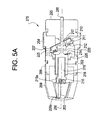
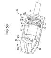
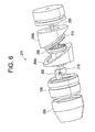
- Figs. 5A - 6 show another example, non-limiting embodiment of a tool chuck 275 with a nutating gear reduction. This example embodiment is similar to the previous example embodiments to the extent that it includes a nutating gear reduction. Also, as in the example embodiment discussed above in section II, this example embodiment may implement "pusher" chuck jaws 202. However, there are several notable differences as described below.
- the cone 209 may include passageways 209a through which the chuck jaws 202 are respectively slidable.
- the passageways 209a of the cone 209 may be inclined relative to the axis 250 of the chuck body 220. In this way, when the chuck jaws 202 are advanced (via the screw 215), the passageways 209a of the cone 209 may influence the chuck jaws 202 in a radial inward direction through the radially oriented passageways 215a of the screw 215 and toward the axis 250.
- the nutating gear 210 may be rotationally fixed.
- the output gear 226 may be driven to rotate by an angular distance equivalent to the difference between the number N3 of teeth 212 of the nutating gear 210 and the number N4 of teeth 214 of the output gear 226.
- the rear sleeve 204 and the front sleeve 206 may rotate relative to the chuck body 220. Further, the rear sleeve 204 and front sleeve 206 may rotate relative to each other. Relative to the chuck body 220, the rear sleeve 204 may rotate in a direction that is counter to the rotational direction of the front sleeve 206.
- the difference in the number N3 of teeth 212 provided on the nutating gear 210 and the number N4 of teeth 214 provided on the output gear 226 may be varied to alter the final output drive ratio of the output gear 226.
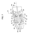
- Fig. 7 shows another example, non-limiting embodiment of a tool chuck 275' with a nutating gear reduction.
- This example embodiment is similar to the example embodiment discussed above in section III. However, this example embodiment may additionally include a switch 240 for disabling the nutating gear reduction mechanism, as described below.
- the tool chuck 275' may include a chuck body 220' defining an axis 250'.
- the rear end of the chuck body 220' may be mounted on a spindle 285' of a power driver 295'.
- the forward end of the screw 215 may include radially oriented passageways in which the chuck jaws 202' are respectively supported.
- the radially oriented passageways may guide a radial movement of the chuck jaws 202', and at the same time may rotationally fix the chuck jaws 202' to the screw 215'.
- the chuck body 220' may support a two-part sleeve inclusive of a front sleeve 206' and a rear sleeve 204'.
- the front sleeve 206' may be mounted for rotation on the chuck body 220'.
- the forward end of the front sleeve 206' may fixedly support a cone 209'.
- the cone 209' may include passageways 209a' through which the chuck jaws 202' are respectively slidable.
- the passageways 209a' in the cone 209' may rotationally fix the cone 209' to the chuck jaws 202'.
- the chuck jaws 202', the cone 209', the front sleeve 206', and the screw 215' may be rotationally fixed together.
- the nutating gear 210' may be arranged in the tool chuck 275' such that its axis is inclined relative to the axis 250' of the chuck body 220'.
- the nutating gear 210' may be mounted in such a way that it remains rotationally fixed relative to the chuck body 220'.
- the nutating gear 210' may include radially inward facing passages 211' that may respectively cooperate with the spherical splines 217'. As the nutating gear 210' nutates, the spherical splines 217' may pass back and forth through the passages 211' and at the same time may prevent the nutating gear 210' from rotating relative to the chuck body 220'.
- the front face of the nutating gear 210' may be provided with a set of teeth 212'.
- the teeth 212' of the nutating gear 210' may engage with the teeth 214' of the output gear 226'.
- the operator may push the switch 240 in an axially rearward direction through the slot 249 of the front sleeve 206'.
- the rearward axial movement of the switch 240 may impart a corresponding rearward axial movement of shift ring 242 and the output gear 226' relative to the chuck body 220'.
- the nut 216' may pass through an opening in the output gear 226'.
- the teeth 214' of the output gear 226' may be engaged with the teeth 212' of the nutating gear 210', thereby enabling the nutating gear reduction mechanism.
- the operator may then turn the rear sleeve 204' to actuate the tool chuck 275' as described above in section III.
- the operator may push the switch 240 in an axially forward direction through the slot 249 of the front sleeve 206'.
- the forward axial movement of the switch 240 may impart a corresponding forward axial movement of shift ring 242 and the output gear 226' relative to the chuck body 220'.
- the nut 216' may pass through an opening in the output gear 226'.
- the teeth 214' of the output gear 226' may be disengaged from the teeth 212' of the nutating gear 210', thereby disabling the nutating gear reduction mechanism.
- the operator may then turn the front sleeve 206' (and thus the cone 209') relative to the chuck body 220'.
- the cone 209' may rotate together with the chuck jaws 202' and the screw 215'.
- the relative rotation between the screw 215' and the nut 216' may advance or retract the screw 215' along the axis 250' (depending on the rotation direction of the front sleeve 206').
- the screw 215' may push or pull on the chuck jaws 202', thereby closing or opening the same.
- the forward end of the chuck body 320 may include a nut 316.
- the nut 316 may be screw coupled to a screw 315.
- the nut 316 may have radially interior threads 318 that engage radially outward facing threads 303 of the screw 315.
- the chuck body 320 (together with the nut 316) may be rotatable relative to the screw 315. During this relative rotation, the interaction of the threads 303, 318 may influence the screw 315 to advance and/or retract along the axis 350 of the chuck body 320.
- the chuck body 320 may support a nutating mechanism housing ("NMH") sleeve 360.
- the NMH sleeve 360 may be rotatable relative to the chuck body 320. Such relative rotation may be facilitated by a bearing 362.
- the NMH sleeve 360 may have a front face 307 that is inclined relative to the axis 350 of the chuck body 320. The front face 307 of the NMH sleeve 360 may act upon the rear face of the nutating gear 310.
- the rear end of the front sleeve 306 may fixedly support an output gear 326.
- the chuck body 320 may extend through an opening of the output gear 326.
- the rear face of the output gear 326 may be provided with a set of teeth 314.
- the nutating gear 310 may be arranged in the tool chuck 375 such that its axis is inclined relative to the axis 350 of the chuck body 320.
- the chuck body 320 may extend through an opening of the nutating gear 310.
- the nutating gear 310 may be mounted in such a way that it remains rotationally fixed relative to the chuck body 320. That is, the nutating gear 310 may nutate without rotating relative to the chuck body 320 about the axis 350.
- the nutating gear 310 may include radially inward facing features that may cooperate with the spherical splines 317 provided on the chuck body 320.
- the radially inward facing features may be in the form of passages 311 that respectively receive the spherical splines 317.
- the passages 311 may extend along a longitudinal axis of the nutating gear 310.
- the spherical splines 317 may pass back and forth through the passages 311 and at the same time may prevent the nutating gear 310 from rotating relative to the chuck body 320.
- a bearing (not illustrated) may be interposed between the NMH sleeve 360 and the nutating gear 310 to facilitate a relative rotational movement between the NMH sleeve 360 and the nutating gear 310.
- the front face of the nutating gear 310 may be provided with a set of teeth 312.
- the teeth 312 of the nutating gear 310 may engage with the teeth 314 of the output gear 326.
- the CL sleeve 370 may be axial moveable relative to the NMH sleeve 360 between the illustrated rearward position (or “chuck drive mode") and a forward position (or “chuck lock mode”). As shown in Fig. 8, in the chuck drive mode, a rear face of the CL sleeve 370 may include features 372 that engage with corresponding features 374 provided on the driver housing. The features 372, 374 may cooperate to rotationally fix the CL sleeve 370 (and thus the NMH sleeve 360) to the driver housing. The features 372, 374 may be designed to have profiles so that they separate from each other when a predetermined torque is applied between the CL sleeve 370 and the driver housing.
- the tool chuck 375 may operate differently depending on the axial position of the CL sleeve 370.
- An operator may push the CL sleeve 370 in an axial rearward direction, as illustrated in Fig. 8, to operate the tool chuck 375 in the chuck drive mode.
- the chuck drive mode may allow the operator to utilize the output of the driver 395 to actuate the chuck jaws 302. This may speed the chuck jaw actuation process, as compared to the manually operated tool chuck described with respect to the previous embodiments.
- the cooperating features 372, 374 may be engaged to rotationally fix together the CL sleeve 370 (and thus the NMH sleeve 360) and the driver housing.
- the protrusions 376 of the CL sleeve 370 may be disengaged from the recesses 378 of the front sleeve 306, and the protrusions 380 of the CL sleeve 370 may be disengaged from the recesses 382 of chuck body 320.
- the front sleeve 306 may be rotatable relative to the CL sleeve 370
- the chuck body 320 may be rotatable relative to the CL sleeve 370.
- the nutating gear 310 may drive the output gear 326 (and thus the front sleeve 306) to rotate by one full revolution plus an angular distance equivalent to the difference between the number N3 of teeth 312 of the nutating gear 310 and the number N4 of teeth 314 of the output gear 326.
- the nut 316 of the chuck body 320 may rotate through one full revolution. In this way, a speed differential may be achieved between the rotationally driven front sleeve 306 and the rotationally driven nut 316.
- the chuck jaws 302 may drive the screw 315 to rotate relative to the nut 316 of the chuck body 320.
- This relative rotation may advance or retract the screw 315 along the axis 350 (depending on the rotation direction of the chuck body 320) by virtue of the interaction between the radially inward facing threads 318 and the radially outward facing threads 303.
- the screw 315 may push or pull on the chuck jaws 302, thereby opening and/or closing the same.
- the cooperating features 372, 374 may function to limit the torque between the CL sleeve 370 and the driver housing. This torque limiting feature may take the operator out of the process, thereby effectively preventing the tool chuck from over tightening.
- the cooperating features 372, 374 may be disengaged so that the CL sleeve 370 (and thus the NMH sleeve 360) may be rotatable relative to the driver housing. Further, the protrusions 376 of the CL sleeve 370 may be engaged with the recesses 378 of the front sleeve 306, and the protrusions 380 of the CL sleeve 370 may be engaged with the recesses 382 of chuck body 320. Thus, the CL sleeve 370, the NMH sleeve 360, and the front sleeve 306 may be rotatable together with the chuck body 320. When the operator actuates the driver 395, the entire tool chuck 375 may rotate together as a Single unit. The detent mechanism 390 cooperating with the recess 392 may retain the CL sleeve in the axially forward position.
- the CL sleeve 370 may prevent any relative rotation from occurring between the front sleeve 306 (and thus the chuck jaws 302 and the screw 315) and the chuck body 320 (and thus the nut 316). In this way, the CL sleeve 370 may prevent the chuck jaws 302 from loosening.
- the CL sleeve may be suitably implemented in other embodiments of the Invention.
- the CL sleeve may be incorporated into the example embodiments discussed above in sections III and IV.
- the incorporated CL sleeve may serve the same advantageous functions described above.
- the various embodiments include chuck bodies that may be separate and distinct elements from the spindle of the driver.
- the spindle and the chuck body may be of a unitary, one-piece construction.
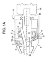
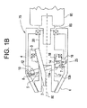
- Figs. 9-11 illustrate a fastener implementing a nutating gear reduction feature that may be somewhat similar to the ones described above.
- the fastener 475 may cooperate with a hub 485 of a saw (not shown) so that a saw blade 495 may be mounted on the saw.
- the fastener 475 may include an external thread 418 that is screw coupled to an internal thread provided on the distal end of the hub 485.
- a washer 497 may be interposed between the fastener 475 and the saw blade 495.
- the fastener 475 may include a housing 404.
- the housing 404 may be of a two-piece construction (as shown in Fig. 11) to facilitate assembly.
- a sleeve 406 may be press fit on the housing 404.
- the exterior surface of the sleeve 406 and/or the housing 404 may be knurled.
- the housing 404 may rotatably support a nutating gear 410 and an anchor flange 405.
- the housing 404 may include a shoulder 420 cooperating with a circumferential groove in the nutating gear 410, and a shoulder 425 cooperating with a circumferential groove in the anchor flange 405.
- the anchor flange 405 may be rotatable relative to the housing 404 about a main axis 450.
- a driven gear 416 may extend through respective openings provided in the nutating gear 410 and the anchor flange 405.
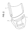
- the nutating gear 410 may be arranged in the housing 404 such that its axis is inclined relative to the main axis 450.
- the nutating gear 410 may includes two sets of teeth: one set of teeth 413a interacts with the anchor flange 405; and another set of teeth 412 interacts with the driven gear 416.
- the anchor flange 405 may include a set of teeth 415 for interacting with the washer 497, and a set of teeth 413b that engage with the teeth 413a on the nutating gear 410.
- the number of teeth 413b on the anchor flange 405 and the number of teeth 413a on the nutating gear 410 may be selected so that the anchor flange 405 and the nutating gear 410 maintain the same relative rotational positions with respect to each other.
- an equal number of the teeth 413a, 413b may be provided.
- different numbers of teeth 413a, 413b may be provided so that the nutating gear 410 may rotate relative to the anchor flange 405.
- Such relative rotation between the nutating gear 410 and the anchor flange 405) may be controlled by varying the difference in the number of teeth 413a, 413b.
- the driven gear 416 may be rotatably supported by the housing 404. To this end, a distal end of the driven gear 416 (to the right in Fig. 10) may extend into an aperture in the housing 404.
- the driven gear 416 may also be rotatably supported by the anchor flange 405. For example, as shown, a tapered bearing surface of the driven gear 416 may abut against a cooperating tapered bearing surface of the anchor flange 405.
- the distal end of the driven gear 416 may include a feature for receiving a tool that a user may optionally utilize to rotationally drive driven gear 416.
- the feature may be a hex recess 417 adapted to receive a Standard Allen wrench (not shown). Numerous and varied tool receiving features (other than the hex recess 417), which are well known in this art, may be suitably implemented.
- a user may rotationally drive the driven gear 416 if the nutating gear reduction becomes inoperable.
- the driven gear 416 may also include a protruding shaft (to the left in Fig. 10) having the external thread 418.
- the external thread 418 may be screw coupled to an internal thread provided on the distal end of the hub 485 (see Fig. 9).
- the driven gear 416 may have a set of teeth 414 that engage with the teeth 412 of the nutating gear 410.
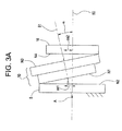
- the nutating gear 410 may be inclined relative to the driven gear 416 so that the teeth 12 of the nutating gear 410 may only touch the teeth 414 of the driven gear 416 at one contact area 426.
- the diameter and circumference of the nutating gear 410 may be larger than that of the driven gear 416.
- the corresponding sets of teeth 412, 414 may be of the same pitch so that the larger nutating gear 410 may have more teeth 412 around its circumference than does the smaller driven gear 416.
- the nutating gear 410 may be rotationally fixed to the anchor flange 405.
- the driven gear 416 may be driven to rotate by an angular distance equivalent to the difference between the number N3 of teeth 412 of the nutating gear 410 and the number N4 of teeth 414 of the driven gear 416.
- a loosening operation may be achieved by turning the sleeve 406 and/or housing 404 in a direction opposite to that of the tightening operation.
- the fastener 475 includes an external thread 418 that cooperates with an internal thread of the hub 485.
- the fastener 475 (specifically, the driven gear 416) may include an internal thread that cooperates with an external thread of the hub.
- the driven gear 416 may be of a two-piece construction to facilitate assembly of the fastener 475.
- the two-piece construction may include a shaft portion 416a and a distal flange portion 416b.
- the distal flange portion 416b which may be fixedly mounted on the shaft portion 416a, may include the teeth 414 that engage with the teeth 412 of the nutating gear 410
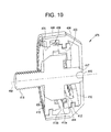
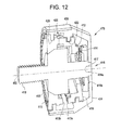
- the fastener 475 depicted in Figs. 12 and 13 may be structurally and functionally similar to the fastener 475 depicted in Figs. 9-11.
- the example fastener may have numerous and varied applications that involve securing parts together (other than securing a saw blade to the hub of a saw).
- the example fastener may be suitable for application where the parts are to be secured together temporarily and without requiring the use of tools (such as keys, wrenches and/or screwdrivers, for example).
- the fastener may be implemented to secure together component parts of framework (such as scaffolding, staging, etc.), recreational equipment (such as the wheel and frame of a bicycle) and lawn and garden equipment (such as lawn mowers, chain saws, etc.).
- the concepts discussed above may be implemented in an instrument to provide a fine adjustment feature.
- Instruments may include telescopes, video cameras, lathes and/or drill presses.
- the anchor flange 405 may be fixed to the instrument housing (or some other supporting structure).
- the nutating gear 410 will nutate and rotationally drive the driven gear 416.
- the nutating gear reduction feature one rotation of the housing 404 would cause only a fractional rotation of the driven gear 416, which may be operatively connected to various gears, optics or other component parts of the instrument.
Landscapes
- Engineering & Computer Science (AREA)
- Mechanical Engineering (AREA)
- Life Sciences & Earth Sciences (AREA)
- Wood Science & Technology (AREA)
- Forests & Forestry (AREA)
- Gripping On Spindles (AREA)
Applications Claiming Priority (1)
| Application Number | Priority Date | Filing Date | Title |
|---|---|---|---|
| US11/551,076 US20070063455A1 (en) | 2004-09-17 | 2006-10-19 | Fastener with nutating gear reduction |
Publications (2)
| Publication Number | Publication Date |
|---|---|
| EP1914031A1 true EP1914031A1 (de) | 2008-04-23 |
| EP1914031B1 EP1914031B1 (de) | 2012-12-05 |
Family
ID=39047794
Family Applications (1)
| Application Number | Title | Priority Date | Filing Date |
|---|---|---|---|
| EP07118247A Not-in-force EP1914031B1 (de) | 2006-10-19 | 2007-10-10 | Halter mit Taumeluntersetzung |
Country Status (3)
| Country | Link |
|---|---|
| US (1) | US20070063455A1 (de) |
| EP (1) | EP1914031B1 (de) |
| CN (1) | CN201180773Y (de) |
Families Citing this family (5)
| Publication number | Priority date | Publication date | Assignee | Title |
|---|---|---|---|---|
| JP2015521964A (ja) * | 2012-07-17 | 2015-08-03 | ウェイハイ ダワン ハードウェア プロダクツ リミテッドWeihaidawang Hardware Products Limited | 新型ドリルチャック |
| CN105889446A (zh) * | 2014-09-24 | 2016-08-24 | 隆礼湘 | 车床进给和光学元件位置的粗微调机构 |
| CN109630633B (zh) * | 2018-12-25 | 2021-09-10 | 西北工业大学 | 一种章动盘式无级变速传动装置 |
| CN111237400B (zh) * | 2020-03-20 | 2023-01-17 | 苏州大学 | 双球面摆线滚子章动传动装置 |
| CN118616814B (zh) * | 2024-05-28 | 2025-01-24 | 广州市义统包装制品有限公司 | 一种茶叶包装罐生产用的切割装置 |
Citations (3)
| Publication number | Priority date | Publication date | Assignee | Title |
|---|---|---|---|---|
| WO1988005386A1 (fr) * | 1987-01-15 | 1988-07-28 | Robert Bosch Gmbh | Dispositif de serrage pour le blocage axial d'un outil, notamment d'une meule |
| EP0924038A2 (de) | 1997-12-01 | 1999-06-23 | Black & Decker Inc. | Werkzeugeinspannvorrichtung für ein angetriebenes Werkzeug |
| US20060061049A1 (en) | 2004-09-17 | 2006-03-23 | Zhang Qiang J | Chuck with nutating gear reduction |
Family Cites Families (47)
| Publication number | Priority date | Publication date | Assignee | Title |
|---|---|---|---|---|
| US613059A (en) * | 1898-10-25 | Bouquet-holder | ||
| US655697A (en) * | 1899-11-11 | 1900-08-14 | William C Dunn | Bicycle. |
| US1159248A (en) * | 1908-12-23 | 1915-11-02 | Horton & Son Company E | Chuck. |
| US1509061A (en) * | 1923-01-13 | 1924-09-16 | P C Miller | Automatic gripping and releasing chuck |
| DE370752C (de) * | 1923-02-14 | 1923-03-06 | Julius Jakowitsch | Futter fuer stangenfoermiges Material |
| US1750023A (en) * | 1925-05-04 | 1930-03-11 | Albert Lee Shepard | Automatic chuck |
| US2661700A (en) * | 1946-05-03 | 1953-12-08 | Electraulic Presses Ltd | Axial type reciprocating pump, compressor, motor, and engine |
| BE657123A (de) * | 1964-02-01 | 1965-04-01 | ||
| US3506277A (en) * | 1967-03-03 | 1970-04-14 | Zimmer Mfg Co | Keyless chuck adapter |
| US3545776A (en) * | 1968-06-18 | 1970-12-08 | Jacobs Mfg Co | Combined chuck spindle and chuck locking collar |
| US3640154A (en) * | 1970-09-11 | 1972-02-08 | Philip E Massie | Axial gear train |
| US4527637A (en) * | 1981-05-11 | 1985-07-09 | Bodine Albert G | Cycloidal drill bit |
| US4260169A (en) * | 1979-11-29 | 1981-04-07 | Hall Robert L | Keyless chuck |
| US4550630A (en) * | 1982-08-23 | 1985-11-05 | Allied Corporation | Hermetically sealed drive |
| US4682918A (en) * | 1984-04-16 | 1987-07-28 | Milwaukee Electric Tool Corporation | Keyless impacting chuck |
| US4660841A (en) * | 1985-01-14 | 1987-04-28 | Chouinard Michael J | Hand tightenable device for holding a cutting implement |
| JPH047843Y2 (de) * | 1987-11-09 | 1992-02-28 | ||
| US5044643A (en) * | 1989-06-16 | 1991-09-03 | Daijiro Nakamura | Tool chuck |
| US5573254A (en) * | 1989-12-11 | 1996-11-12 | Power Tool Holders Incorporated | Non-impact keyless chuck |
| US5125673A (en) * | 1989-12-11 | 1992-06-30 | Huff Robert O | Non-impact keyless chuck |
| DE4005757A1 (de) * | 1990-02-23 | 1991-08-29 | Bosch Gmbh Robert | Handwerkzeugmaschine mit bohrfutter |
| US5094147A (en) * | 1990-06-13 | 1992-03-10 | Shaw Edwin L | High torque low speed motor |
| JPH05180301A (ja) * | 1991-04-08 | 1993-07-20 | Delta:Kk | 減速機構のトルクリミッタ |
| US5145194A (en) * | 1991-06-21 | 1992-09-08 | Jacobs Chuck Technology Corporation | Impact tool chuck |
| JPH0647606A (ja) * | 1991-09-12 | 1994-02-22 | Jacobs Japan Inc | ツールチャック |
| JPH05301107A (ja) * | 1991-11-11 | 1993-11-16 | Jacobs Japan Inc | ツールチャック |
| US5215317A (en) * | 1992-05-18 | 1993-06-01 | Jacobs Chuck Technology Corp. | Keyless chuck |
| DE4313742C2 (de) * | 1993-04-27 | 2000-10-05 | Roehm Guenter H | Bohrfutter |
| US5348318A (en) * | 1993-08-13 | 1994-09-20 | Jacobs Chuck Technology Corporation | Chuck |
| US5499828A (en) * | 1994-03-04 | 1996-03-19 | Power Tool Holders Incorporated | Lever bar keyless chuck |
| US5511801A (en) * | 1994-04-01 | 1996-04-30 | Power Tool Holders, Inc. | Integrated collet and chuck device |
| US5553873A (en) * | 1994-07-01 | 1996-09-10 | Power Tool Holders Incorporated | Keyless chuck |
| ES2108610B1 (es) * | 1994-07-22 | 1998-07-01 | Llambrich Precision S A | Portabrocas de maquinas herramienta. |
| DE19506708C1 (de) * | 1995-02-25 | 1996-03-28 | Roehm Guenter H | Bohrvorrichtung |
| US5701779A (en) * | 1995-03-23 | 1997-12-30 | Power Tool Holders Incorporated | Chuck having formed jaws |
| US6045141A (en) * | 1997-08-06 | 2000-04-04 | Power Tool Holders, Inc. | Molded chuck |
| US5918887A (en) * | 1998-01-30 | 1999-07-06 | Power Tool Holders Incorporated | Drill chuck with matching jaw and jaw passageways |
| JP2000061716A (ja) * | 1998-08-13 | 2000-02-29 | Yukiwa Seiko Inc | チャック装置 |
| JP2000158270A (ja) * | 1998-09-25 | 2000-06-13 | Seiwa Seiki Kk | ツールホルダ |
| US6139228A (en) * | 1998-12-04 | 2000-10-31 | Stryker Corporation | Keyless chuck assembly for a rotary driven tool |
| US6390481B1 (en) * | 2000-03-10 | 2002-05-21 | Power Tool Holders Incorporated | Locking chuck |
| EP1170079B2 (de) * | 2000-07-03 | 2010-10-06 | Röhm GmbH | Bohrfutter |
| AUPR272101A0 (en) * | 2001-01-24 | 2001-02-22 | Bayly Design Associates Pty Ltd | Power tool |
| JP2003071618A (ja) * | 2001-08-30 | 2003-03-12 | Yukiwa Seiko Inc | チャック装置 |
| DE10149959A1 (de) * | 2001-10-10 | 2003-04-17 | Roehm Gmbh | Bohrvorrichtung |
| US6616148B1 (en) * | 2002-03-22 | 2003-09-09 | Jerry Corcoran | Keyless chuck with backup key operation |
| JP4294945B2 (ja) * | 2002-12-06 | 2009-07-15 | ユキワ精工株式会社 | チャック装置 |
-
2006
- 2006-10-19 US US11/551,076 patent/US20070063455A1/en not_active Abandoned
-
2007
- 2007-10-10 EP EP07118247A patent/EP1914031B1/de not_active Not-in-force
- 2007-10-19 CN CNU2007203115394U patent/CN201180773Y/zh not_active Expired - Fee Related
Patent Citations (3)
| Publication number | Priority date | Publication date | Assignee | Title |
|---|---|---|---|---|
| WO1988005386A1 (fr) * | 1987-01-15 | 1988-07-28 | Robert Bosch Gmbh | Dispositif de serrage pour le blocage axial d'un outil, notamment d'une meule |
| EP0924038A2 (de) | 1997-12-01 | 1999-06-23 | Black & Decker Inc. | Werkzeugeinspannvorrichtung für ein angetriebenes Werkzeug |
| US20060061049A1 (en) | 2004-09-17 | 2006-03-23 | Zhang Qiang J | Chuck with nutating gear reduction |
Also Published As
| Publication number | Publication date |
|---|---|
| CN201180773Y (zh) | 2009-01-14 |
| US20070063455A1 (en) | 2007-03-22 |
| EP1914031B1 (de) | 2012-12-05 |
Similar Documents
| Publication | Publication Date | Title |
|---|---|---|
| EP1789224B1 (de) | Spannfutter mit taumeluntersetzung | |
| EP2087958B1 (de) | Selbstverriegelndes Futter | |
| TW555632B (en) | Method of assembling a power driver and a geared tool holder for use with a power driver | |
| US7722054B2 (en) | Chuck with torque indicator | |
| EP1324847B1 (de) | Spannfutter mit verbesserter schnittstellenbaueinheit für kraftantrieb | |
| US9358617B2 (en) | Chuck | |
| US5826888A (en) | Quick release chuck device | |
| US20130133908A1 (en) | Power drill with adjustable torque | |
| JPH11262809A (ja) | 手動操作される穿孔機若しくは打撃穿孔機 | |
| US20060027978A1 (en) | Chuck with spindle lock | |
| AU2006201470A1 (en) | Rotatable chuck | |
| EP1914031B1 (de) | Halter mit Taumeluntersetzung | |
| US7645101B2 (en) | Chuck with internally threaded jaw in a PTO application | |
| US5820134A (en) | Drill chuck for machine tools | |
| GB2451930A (en) | Locking chuck | |
| US7850404B2 (en) | Drill chuck | |
| US6616148B1 (en) | Keyless chuck with backup key operation | |
| CN109530742B (zh) | 卡盘式手紧扳手式增力夹头 | |
| WO2013078381A1 (en) | Chuck with jam release | |
| JPH10175106A (ja) | 締め付け具 |
Legal Events
| Date | Code | Title | Description |
|---|---|---|---|
| PUAI | Public reference made under article 153(3) epc to a published international application that has entered the european phase |
Free format text: ORIGINAL CODE: 0009012 |
|
| AK | Designated contracting states |
Kind code of ref document: A1 Designated state(s): AT BE BG CH CY CZ DE DK EE ES FI FR GB GR HU IE IS IT LI LT LU LV MC MT NL PL PT RO SE SI SK TR |
|
| AX | Request for extension of the european patent |
Extension state: AL BA HR MK RS |
|
| 17P | Request for examination filed |
Effective date: 20080506 |
|
| 17Q | First examination report despatched |
Effective date: 20080605 |
|
| AKX | Designation fees paid |
Designated state(s): AT BE BG CH CY CZ DE DK EE ES FI FR GB GR HU IE IS IT LI LT LU LV MC MT NL PL PT RO SE SI SK TR |
|
| GRAP | Despatch of communication of intention to grant a patent |
Free format text: ORIGINAL CODE: EPIDOSNIGR1 |
|
| GRAS | Grant fee paid |
Free format text: ORIGINAL CODE: EPIDOSNIGR3 |
|
| GRAA | (expected) grant |
Free format text: ORIGINAL CODE: 0009210 |
|
| AK | Designated contracting states |
Kind code of ref document: B1 Designated state(s): AT BE BG CH CY CZ DE DK EE ES FI FR GB GR HU IE IS IT LI LT LU LV MC MT NL PL PT RO SE SI SK TR |
|
| REG | Reference to a national code |
Ref country code: GB Ref legal event code: FG4D |
|
| REG | Reference to a national code |
Ref country code: CH Ref legal event code: EP |
|
| REG | Reference to a national code |
Ref country code: AT Ref legal event code: REF Ref document number: 586983 Country of ref document: AT Kind code of ref document: T Effective date: 20121215 |
|
| REG | Reference to a national code |
Ref country code: IE Ref legal event code: FG4D |
|
| REG | Reference to a national code |
Ref country code: DE Ref legal event code: R096 Ref document number: 602007027103 Country of ref document: DE Effective date: 20130131 |
|
| REG | Reference to a national code |
Ref country code: AT Ref legal event code: MK05 Ref document number: 586983 Country of ref document: AT Kind code of ref document: T Effective date: 20121205 |
|
| PG25 | Lapsed in a contracting state [announced via postgrant information from national office to epo] |
Ref country code: LT Free format text: LAPSE BECAUSE OF FAILURE TO SUBMIT A TRANSLATION OF THE DESCRIPTION OR TO PAY THE FEE WITHIN THE PRESCRIBED TIME-LIMIT Effective date: 20121205 Ref country code: FI Free format text: LAPSE BECAUSE OF FAILURE TO SUBMIT A TRANSLATION OF THE DESCRIPTION OR TO PAY THE FEE WITHIN THE PRESCRIBED TIME-LIMIT Effective date: 20121205 Ref country code: SE Free format text: LAPSE BECAUSE OF FAILURE TO SUBMIT A TRANSLATION OF THE DESCRIPTION OR TO PAY THE FEE WITHIN THE PRESCRIBED TIME-LIMIT Effective date: 20121205 Ref country code: ES Free format text: LAPSE BECAUSE OF FAILURE TO SUBMIT A TRANSLATION OF THE DESCRIPTION OR TO PAY THE FEE WITHIN THE PRESCRIBED TIME-LIMIT Effective date: 20130316 |
|
| REG | Reference to a national code |
Ref country code: NL Ref legal event code: VDEP Effective date: 20121205 |
|
| REG | Reference to a national code |
Ref country code: LT Ref legal event code: MG4D |
|
| PG25 | Lapsed in a contracting state [announced via postgrant information from national office to epo] |
Ref country code: LV Free format text: LAPSE BECAUSE OF FAILURE TO SUBMIT A TRANSLATION OF THE DESCRIPTION OR TO PAY THE FEE WITHIN THE PRESCRIBED TIME-LIMIT Effective date: 20121205 Ref country code: SI Free format text: LAPSE BECAUSE OF FAILURE TO SUBMIT A TRANSLATION OF THE DESCRIPTION OR TO PAY THE FEE WITHIN THE PRESCRIBED TIME-LIMIT Effective date: 20121205 Ref country code: PL Free format text: LAPSE BECAUSE OF FAILURE TO SUBMIT A TRANSLATION OF THE DESCRIPTION OR TO PAY THE FEE WITHIN THE PRESCRIBED TIME-LIMIT Effective date: 20121205 Ref country code: GR Free format text: LAPSE BECAUSE OF FAILURE TO SUBMIT A TRANSLATION OF THE DESCRIPTION OR TO PAY THE FEE WITHIN THE PRESCRIBED TIME-LIMIT Effective date: 20130306 |
|
| PG25 | Lapsed in a contracting state [announced via postgrant information from national office to epo] |
Ref country code: AT Free format text: LAPSE BECAUSE OF FAILURE TO SUBMIT A TRANSLATION OF THE DESCRIPTION OR TO PAY THE FEE WITHIN THE PRESCRIBED TIME-LIMIT Effective date: 20121205 |
|
| PG25 | Lapsed in a contracting state [announced via postgrant information from national office to epo] |
Ref country code: BG Free format text: LAPSE BECAUSE OF FAILURE TO SUBMIT A TRANSLATION OF THE DESCRIPTION OR TO PAY THE FEE WITHIN THE PRESCRIBED TIME-LIMIT Effective date: 20130305 Ref country code: SK Free format text: LAPSE BECAUSE OF FAILURE TO SUBMIT A TRANSLATION OF THE DESCRIPTION OR TO PAY THE FEE WITHIN THE PRESCRIBED TIME-LIMIT Effective date: 20121205 Ref country code: EE Free format text: LAPSE BECAUSE OF FAILURE TO SUBMIT A TRANSLATION OF THE DESCRIPTION OR TO PAY THE FEE WITHIN THE PRESCRIBED TIME-LIMIT Effective date: 20121205 Ref country code: BE Free format text: LAPSE BECAUSE OF FAILURE TO SUBMIT A TRANSLATION OF THE DESCRIPTION OR TO PAY THE FEE WITHIN THE PRESCRIBED TIME-LIMIT Effective date: 20121205 Ref country code: IS Free format text: LAPSE BECAUSE OF FAILURE TO SUBMIT A TRANSLATION OF THE DESCRIPTION OR TO PAY THE FEE WITHIN THE PRESCRIBED TIME-LIMIT Effective date: 20130405 Ref country code: CZ Free format text: LAPSE BECAUSE OF FAILURE TO SUBMIT A TRANSLATION OF THE DESCRIPTION OR TO PAY THE FEE WITHIN THE PRESCRIBED TIME-LIMIT Effective date: 20121205 |
|
| PG25 | Lapsed in a contracting state [announced via postgrant information from national office to epo] |
Ref country code: RO Free format text: LAPSE BECAUSE OF FAILURE TO SUBMIT A TRANSLATION OF THE DESCRIPTION OR TO PAY THE FEE WITHIN THE PRESCRIBED TIME-LIMIT Effective date: 20121205 Ref country code: PT Free format text: LAPSE BECAUSE OF FAILURE TO SUBMIT A TRANSLATION OF THE DESCRIPTION OR TO PAY THE FEE WITHIN THE PRESCRIBED TIME-LIMIT Effective date: 20130405 Ref country code: NL Free format text: LAPSE BECAUSE OF FAILURE TO SUBMIT A TRANSLATION OF THE DESCRIPTION OR TO PAY THE FEE WITHIN THE PRESCRIBED TIME-LIMIT Effective date: 20121205 |
|
| PLBE | No opposition filed within time limit |
Free format text: ORIGINAL CODE: 0009261 |
|
| STAA | Information on the status of an ep patent application or granted ep patent |
Free format text: STATUS: NO OPPOSITION FILED WITHIN TIME LIMIT |
|
| PG25 | Lapsed in a contracting state [announced via postgrant information from national office to epo] |
Ref country code: DK Free format text: LAPSE BECAUSE OF FAILURE TO SUBMIT A TRANSLATION OF THE DESCRIPTION OR TO PAY THE FEE WITHIN THE PRESCRIBED TIME-LIMIT Effective date: 20121205 |
|
| 26N | No opposition filed |
Effective date: 20130906 |
|
| PG25 | Lapsed in a contracting state [announced via postgrant information from national office to epo] |
Ref country code: CY Free format text: LAPSE BECAUSE OF FAILURE TO SUBMIT A TRANSLATION OF THE DESCRIPTION OR TO PAY THE FEE WITHIN THE PRESCRIBED TIME-LIMIT Effective date: 20121205 |
|
| PG25 | Lapsed in a contracting state [announced via postgrant information from national office to epo] |
Ref country code: IT Free format text: LAPSE BECAUSE OF FAILURE TO SUBMIT A TRANSLATION OF THE DESCRIPTION OR TO PAY THE FEE WITHIN THE PRESCRIBED TIME-LIMIT Effective date: 20121205 |
|
| REG | Reference to a national code |
Ref country code: DE Ref legal event code: R097 Ref document number: 602007027103 Country of ref document: DE Effective date: 20130906 |
|
| PG25 | Lapsed in a contracting state [announced via postgrant information from national office to epo] |
Ref country code: MC Free format text: LAPSE BECAUSE OF FAILURE TO SUBMIT A TRANSLATION OF THE DESCRIPTION OR TO PAY THE FEE WITHIN THE PRESCRIBED TIME-LIMIT Effective date: 20121205 |
|
| REG | Reference to a national code |
Ref country code: CH Ref legal event code: PL |
|
| REG | Reference to a national code |
Ref country code: IE Ref legal event code: MM4A |
|
| PG25 | Lapsed in a contracting state [announced via postgrant information from national office to epo] |
Ref country code: CH Free format text: LAPSE BECAUSE OF NON-PAYMENT OF DUE FEES Effective date: 20131031 Ref country code: LI Free format text: LAPSE BECAUSE OF NON-PAYMENT OF DUE FEES Effective date: 20131031 |
|
| REG | Reference to a national code |
Ref country code: FR Ref legal event code: ST Effective date: 20140630 |
|
| PG25 | Lapsed in a contracting state [announced via postgrant information from national office to epo] |
Ref country code: FR Free format text: LAPSE BECAUSE OF NON-PAYMENT OF DUE FEES Effective date: 20131031 |
|
| PG25 | Lapsed in a contracting state [announced via postgrant information from national office to epo] |
Ref country code: IE Free format text: LAPSE BECAUSE OF NON-PAYMENT OF DUE FEES Effective date: 20131010 |
|
| PG25 | Lapsed in a contracting state [announced via postgrant information from national office to epo] |
Ref country code: TR Free format text: LAPSE BECAUSE OF FAILURE TO SUBMIT A TRANSLATION OF THE DESCRIPTION OR TO PAY THE FEE WITHIN THE PRESCRIBED TIME-LIMIT Effective date: 20121205 |
|
| PG25 | Lapsed in a contracting state [announced via postgrant information from national office to epo] |
Ref country code: HU Free format text: LAPSE BECAUSE OF FAILURE TO SUBMIT A TRANSLATION OF THE DESCRIPTION OR TO PAY THE FEE WITHIN THE PRESCRIBED TIME-LIMIT; INVALID AB INITIO Effective date: 20071010 Ref country code: LU Free format text: LAPSE BECAUSE OF NON-PAYMENT OF DUE FEES Effective date: 20131010 |
|
| PG25 | Lapsed in a contracting state [announced via postgrant information from national office to epo] |
Ref country code: MT Free format text: LAPSE BECAUSE OF FAILURE TO SUBMIT A TRANSLATION OF THE DESCRIPTION OR TO PAY THE FEE WITHIN THE PRESCRIBED TIME-LIMIT Effective date: 20121205 |
|
| PGFP | Annual fee paid to national office [announced via postgrant information from national office to epo] |
Ref country code: GB Payment date: 20191010 Year of fee payment: 13 |
|
| PGFP | Annual fee paid to national office [announced via postgrant information from national office to epo] |
Ref country code: DE Payment date: 20200929 Year of fee payment: 14 |
|
| GBPC | Gb: european patent ceased through non-payment of renewal fee |
Effective date: 20201010 |
|
| PG25 | Lapsed in a contracting state [announced via postgrant information from national office to epo] |
Ref country code: GB Free format text: LAPSE BECAUSE OF NON-PAYMENT OF DUE FEES Effective date: 20201010 |
|
| REG | Reference to a national code |
Ref country code: DE Ref legal event code: R119 Ref document number: 602007027103 Country of ref document: DE |
|
| PG25 | Lapsed in a contracting state [announced via postgrant information from national office to epo] |
Ref country code: DE Free format text: LAPSE BECAUSE OF NON-PAYMENT OF DUE FEES Effective date: 20220503 |