EP1914137A2 - Soupape de frein de remorque pour remorques à commande de freinage électronique et à sécurité améliorée du remorque stationnée - Google Patents
Soupape de frein de remorque pour remorques à commande de freinage électronique et à sécurité améliorée du remorque stationnée Download PDFInfo
- Publication number
- EP1914137A2 EP1914137A2 EP08002081A EP08002081A EP1914137A2 EP 1914137 A2 EP1914137 A2 EP 1914137A2 EP 08002081 A EP08002081 A EP 08002081A EP 08002081 A EP08002081 A EP 08002081A EP 1914137 A2 EP1914137 A2 EP 1914137A2
- Authority
- EP
- European Patent Office
- Prior art keywords
- valve
- pressure
- brake
- trailer
- connection
- Prior art date
- Legal status (The legal status is an assumption and is not a legal conclusion. Google has not performed a legal analysis and makes no representation as to the accuracy of the status listed.)
- Withdrawn
Links
- 230000009471 action Effects 0.000 claims abstract description 8
- 230000000694 effects Effects 0.000 claims description 11
- 238000007789 sealing Methods 0.000 claims description 6
- 230000008901 benefit Effects 0.000 description 14
- 230000008878 coupling Effects 0.000 description 13
- 238000010168 coupling process Methods 0.000 description 13
- 238000005859 coupling reaction Methods 0.000 description 13
- 230000001419 dependent effect Effects 0.000 description 9
- 238000010586 diagram Methods 0.000 description 8
- 238000013461 design Methods 0.000 description 7
- 238000009423 ventilation Methods 0.000 description 6
- 238000011161 development Methods 0.000 description 5
- 230000018109 developmental process Effects 0.000 description 5
- 230000007704 transition Effects 0.000 description 5
- 238000009530 blood pressure measurement Methods 0.000 description 4
- 150000001875 compounds Chemical class 0.000 description 4
- 238000005096 rolling process Methods 0.000 description 4
- 238000013022 venting Methods 0.000 description 4
- 238000004519 manufacturing process Methods 0.000 description 3
- 230000029058 respiratory gaseous exchange Effects 0.000 description 3
- 230000007423 decrease Effects 0.000 description 2
- 230000008030 elimination Effects 0.000 description 2
- 238000003379 elimination reaction Methods 0.000 description 2
- 238000009434 installation Methods 0.000 description 2
- 230000003993 interaction Effects 0.000 description 2
- 238000003825 pressing Methods 0.000 description 2
- 239000000243 solution Substances 0.000 description 2
- 230000001960 triggered effect Effects 0.000 description 2
- SFHYNDMGZXWXBU-LIMNOBDPSA-N 6-amino-2-[[(e)-(3-formylphenyl)methylideneamino]carbamoylamino]-1,3-dioxobenzo[de]isoquinoline-5,8-disulfonic acid Chemical compound O=C1C(C2=3)=CC(S(O)(=O)=O)=CC=3C(N)=C(S(O)(=O)=O)C=C2C(=O)N1NC(=O)N\N=C\C1=CC=CC(C=O)=C1 SFHYNDMGZXWXBU-LIMNOBDPSA-N 0.000 description 1
- 238000013459 approach Methods 0.000 description 1
- 230000033228 biological regulation Effects 0.000 description 1
- 238000005352 clarification Methods 0.000 description 1
- 238000010276 construction Methods 0.000 description 1
- 230000001934 delay Effects 0.000 description 1
- 230000003111 delayed effect Effects 0.000 description 1
- 238000009826 distribution Methods 0.000 description 1
- 238000005516 engineering process Methods 0.000 description 1
- 238000002347 injection Methods 0.000 description 1
- 239000007924 injection Substances 0.000 description 1
- 230000004048 modification Effects 0.000 description 1
- 238000012986 modification Methods 0.000 description 1
- 230000002265 prevention Effects 0.000 description 1
- 230000009467 reduction Effects 0.000 description 1
- 230000001105 regulatory effect Effects 0.000 description 1
- 230000004044 response Effects 0.000 description 1
- 230000008054 signal transmission Effects 0.000 description 1
Images


Classifications
-
- B—PERFORMING OPERATIONS; TRANSPORTING
- B60—VEHICLES IN GENERAL
- B60T—VEHICLE BRAKE CONTROL SYSTEMS OR PARTS THEREOF; BRAKE CONTROL SYSTEMS OR PARTS THEREOF, IN GENERAL; ARRANGEMENT OF BRAKING ELEMENTS ON VEHICLES IN GENERAL; PORTABLE DEVICES FOR PREVENTING UNWANTED MOVEMENT OF VEHICLES; VEHICLE MODIFICATIONS TO FACILITATE COOLING OF BRAKES
- B60T15/00—Construction arrangement, or operation of valves incorporated in power brake systems and not covered by groups B60T11/00 or B60T13/00
- B60T15/02—Application and release valves
- B60T15/025—Electrically controlled valves
- B60T15/027—Electrically controlled valves in pneumatic systems
-
- B—PERFORMING OPERATIONS; TRANSPORTING
- B60—VEHICLES IN GENERAL
- B60T—VEHICLE BRAKE CONTROL SYSTEMS OR PARTS THEREOF; BRAKE CONTROL SYSTEMS OR PARTS THEREOF, IN GENERAL; ARRANGEMENT OF BRAKING ELEMENTS ON VEHICLES IN GENERAL; PORTABLE DEVICES FOR PREVENTING UNWANTED MOVEMENT OF VEHICLES; VEHICLE MODIFICATIONS TO FACILITATE COOLING OF BRAKES
- B60T15/00—Construction arrangement, or operation of valves incorporated in power brake systems and not covered by groups B60T11/00 or B60T13/00
- B60T15/02—Application and release valves
- B60T15/18—Triple or other relay valves which allow step-wise application or release and which are actuated by brake-pipe pressure variation to connect brake cylinders or equivalent to compressed air or vacuum source or atmosphere
- B60T15/24—Triple or other relay valves which allow step-wise application or release and which are actuated by brake-pipe pressure variation to connect brake cylinders or equivalent to compressed air or vacuum source or atmosphere controlled by three fluid pressures
- B60T15/243—Trailer control valves
-
- B—PERFORMING OPERATIONS; TRANSPORTING
- B60—VEHICLES IN GENERAL
- B60T—VEHICLE BRAKE CONTROL SYSTEMS OR PARTS THEREOF; BRAKE CONTROL SYSTEMS OR PARTS THEREOF, IN GENERAL; ARRANGEMENT OF BRAKING ELEMENTS ON VEHICLES IN GENERAL; PORTABLE DEVICES FOR PREVENTING UNWANTED MOVEMENT OF VEHICLES; VEHICLE MODIFICATIONS TO FACILITATE COOLING OF BRAKES
- B60T8/00—Arrangements for adjusting wheel-braking force to meet varying vehicular or ground-surface conditions, e.g. limiting or varying distribution of braking force
- B60T8/32—Arrangements for adjusting wheel-braking force to meet varying vehicular or ground-surface conditions, e.g. limiting or varying distribution of braking force responsive to a speed condition, e.g. acceleration or deceleration
- B60T8/321—Arrangements for adjusting wheel-braking force to meet varying vehicular or ground-surface conditions, e.g. limiting or varying distribution of braking force responsive to a speed condition, e.g. acceleration or deceleration deceleration
- B60T8/323—Systems specially adapted for tractor-trailer combinations
-
- B—PERFORMING OPERATIONS; TRANSPORTING
- B60—VEHICLES IN GENERAL
- B60T—VEHICLE BRAKE CONTROL SYSTEMS OR PARTS THEREOF; BRAKE CONTROL SYSTEMS OR PARTS THEREOF, IN GENERAL; ARRANGEMENT OF BRAKING ELEMENTS ON VEHICLES IN GENERAL; PORTABLE DEVICES FOR PREVENTING UNWANTED MOVEMENT OF VEHICLES; VEHICLE MODIFICATIONS TO FACILITATE COOLING OF BRAKES
- B60T8/00—Arrangements for adjusting wheel-braking force to meet varying vehicular or ground-surface conditions, e.g. limiting or varying distribution of braking force
- B60T8/32—Arrangements for adjusting wheel-braking force to meet varying vehicular or ground-surface conditions, e.g. limiting or varying distribution of braking force responsive to a speed condition, e.g. acceleration or deceleration
- B60T8/321—Arrangements for adjusting wheel-braking force to meet varying vehicular or ground-surface conditions, e.g. limiting or varying distribution of braking force responsive to a speed condition, e.g. acceleration or deceleration deceleration
- B60T8/3255—Systems in which the braking action is dependent on brake pedal data
- B60T8/327—Pneumatic systems
-
- B—PERFORMING OPERATIONS; TRANSPORTING
- B60—VEHICLES IN GENERAL
- B60T—VEHICLE BRAKE CONTROL SYSTEMS OR PARTS THEREOF; BRAKE CONTROL SYSTEMS OR PARTS THEREOF, IN GENERAL; ARRANGEMENT OF BRAKING ELEMENTS ON VEHICLES IN GENERAL; PORTABLE DEVICES FOR PREVENTING UNWANTED MOVEMENT OF VEHICLES; VEHICLE MODIFICATIONS TO FACILITATE COOLING OF BRAKES
- B60T8/00—Arrangements for adjusting wheel-braking force to meet varying vehicular or ground-surface conditions, e.g. limiting or varying distribution of braking force
- B60T8/32—Arrangements for adjusting wheel-braking force to meet varying vehicular or ground-surface conditions, e.g. limiting or varying distribution of braking force responsive to a speed condition, e.g. acceleration or deceleration
- B60T8/34—Arrangements for adjusting wheel-braking force to meet varying vehicular or ground-surface conditions, e.g. limiting or varying distribution of braking force responsive to a speed condition, e.g. acceleration or deceleration having a fluid pressure regulator responsive to a speed condition
- B60T8/349—Systems adapted to control a set of axles, e.g. tandem axles
Definitions
- Such a trailer brake valve is out of DE 28 10 850 A1 known.
- the breakaway protection for the coupling hose "supply” is implemented; if the connection for the supply air [there automatic brake connection (20)] is depressurized, then the emergency brake piston [there (22)] becomes depressurized on its upper side and that on its Bottom adjoining reservoir pressure pushes it up so that first the exhaust valve [there (26, 28)] closes and in the further upward movement, the inlet valve [there (26, 27)] is opened, so that the at the reservoir terminal [there ( 33)] is also transmitted pressure in the brake chamber and rests against the brake cylinder connections.
- the function of an overfeed of the brake pressure transmitted to the brake cylinder is further integrated with respect to the pneumatic brake signal.
- a load-dependent regulated dual-line trailer brake system which consists of a valve designed as a seat valve emergency brake valve [there (3)] and a load-dependent controlled brake force controller there (5)], this as a combination of a load-dependent acting control part with an air flow intensifying Relay valve is formed.
- the emergency brake valve corresponds in its operation of the tear function in a conventional trailer brake valve, so that the function of both valves can be understood as the function of a trailer brake valve with load-controlled braking force control mutatis mutandis. This is especially true, as well as a trailer brake valve z. B.
- the parking and maneuvering modes of the parking and maneuvering valves namely, "parking", “driving” and “maneuvering” are preselected by only one control knob provided with an operation knob [there (7)], which is for Control of the respective operating mode can take three switching positions.
- Another difference of the parking and maneuvering valve to the combination trailer brake valve / combination release valve is that when parking as well as while driving in a supply line demolition [or dissolved supply clutch] not the service brake but the parking brake takes effect.
- a supply line demolition or dissolved supply clutch
- the double release valve [there (1) under "Diagram with ALB trailer brake valve”] consists of a service brake release valve [in Fig. 1 (33)], a parking valve [in Fig. 1 (20)] and a check valve associated with the parking valve.
- the service brake release valve is pneumatic on the input side [there (1-1)] with the supply coupling head [in Fig. 1 (48)] and on the output side pneumatically connected to the supply pressure connection [there (1) of the local ALB trailer brake valve (2), in FIG Fig. 1 (1) of the trailer brake valve (8)] connected.
- the service brake release valve In its driving position [pulled position of the local black operating knob], the service brake release valve has no effect on the pressure in the service brake chambers of the spring brake cylinder; in its release position [not pulled position of the black actuating button], the service brake release valve causes the release of the service brakes.
- the service brake release valve is used to move a decoupled trailer by overriding the automatic brake [triggered by the supply line breakaway in the trailer brake valve]; This happens because in the release position tank pressure is deflected and fed to the supply connection in the trailer brake valve [in Fig. 1 from the release connection (5) via the pressure channel (24) to the supply connection (1)]; By this pressure deflection is simulated in the trailer brake valve that is applied to the coupling head for the supply pressure hose pressure.
- the parking valve vented in its parking position - [pulled position of the local red actuator button] the release chambers of the spring brake cylinders, so that the parking brakes are effective; In its driving position [not pulled position of the red actuating button], the parking valve releases the parking brakes by ventilating the spring-loaded release chambers.
- This well-known law prescribed function of the check valve is also effective in a parked trailer, which by uncoupling in the automatic Brake function goes and in which the parking valve remains in the driving position.
- a brake pressure modulator For the generation of the brake pressure, a brake pressure modulator is provided, which consists of electrically controllable valves, which are usually controlled in clocking mode of operation of the brake control electronics and serve as pilot valves for generating a control pressure in the control chamber of a relay valve, which air mass amplifies the control pressure as a brake pressure on its output to one or more brake cylinders; In this case, one or more brake control channels constructed in this way can be implemented.
- a trailer brake valve for use in a trailer with electronic brake control therefore needs neither the function of the air quantity gain nor special functions such.
- For such a trailer brake valve it is quite sufficient if the basic functions, namely the provision of the transmitted braking force from the towing vehicle, the anti-tamper and the possibility of connection of a double-release valve explained above are realized.
- the invention is therefore the object of a trailer brake valve after the former known
- the invention has the advantage that no additional components or piping are required for increased safety against unintentional rolling on the trailer side.
- the invention has the advantage that the susceptibility to errors is significantly reduced by the significantly simplified compared to the prior art construction.
- Relay valves are not free from air consumption due to the venting of the relay valve pressure chamber.
- the relay valve principle working valve device according to the invention has the advantage that no more air consumption takes place and associated with an air consumption noise also does not take place.
- a development of the invention has the advantage that by eliminating the relay valve with its time delay "output input" of i. Gen. more than 30 ms, a time advantage for the electrical signal of the pressure sensor is connected, because this pressure sensor measures the output from the trailer brake valve brake pressure.
- the pneumatic path is optimized, because this is provided in contrast to the normally effective electrical brake signal transmission only for emergency braking, in which can be dispensed with a load-dependent brake pressure influencing.
- the optimized pneumatic path has the advantage that on the one hand accounts air-consuming facilities and on the other time delays caused by such facilities no longer occur.
- Another development of the invention has the advantage that the switching of the trailer brake valve in the tear-off position depends only on the supply port of the valve [this is pneumatically connected to the red coupling head] applied pressure. The transition from one to the other switching position also takes place abruptly, so that the switching is also independent of friction and creeping transitions are avoided.
- the emergency braking "immediately", and it must be compared with conventional solutions initially no characteristic traversed.
- the valve is designed as a pressure compensated positive overlap valve; Compared to conventional solutions, this development also has the advantage that breathing spaces and the associated risk of icing are avoided.
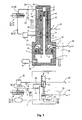
- Fig. 1 Based on Fig. 1 the functional scope of the trailer brake valve for a trailer EBS brake system will be explained; In this case, it will be explained on the basis of the realization, in which way already mentioned functions that can be omitted, are taken over by the trailer EBS brake pressure control.
- FIG. 1 The block diagram after Fig. 1 it is based on the configuration of a base variant for trailer EBS systems, which consists of a semi-trailer (34) with two axles, this is a 2S / 2M system [two ABS sensors for two wheels and two Modulator channels for the wheel brakes the left and the right side]; the ABS brake pressure control is thus carried out page by page.
- a base variant for trailer EBS systems which consists of a semi-trailer (34) with two axles, this is a 2S / 2M system [two ABS sensors for two wheels and two Modulator channels for the wheel brakes the left and the right side]; the ABS brake pressure control is thus carried out page by page.
- a supply pressure hose for transmitting the supply pressure [attached to the towing vehicle red pressure hose, which is coupled via the "red coupling head" (48) of the trailer]
- a brake pressure hose (31) for transmitting the brake pressure [tractor-mounted yellow wire coupled via the trailer's yellow coupling head (49)].
- a trailer control valve [AST valve].
- the supply pressure hose (30) is pneumatically connected via the above-described service brake release valve (33) to the supply port (1), and the brake pressure hose (31) via a pneumatic line to the brake specification port (4) of the trailer brake valve (8) ,
- the trailer brake valve (8) further has a container port (3) to which the reservoir pressure vessel (9) is connected for the trailer, and a brake pressure port (2), at which the pneumatic brake pressure to the pneumatic input (28) of the pneumatic Bremstikmodulators (29) is output;
- This brake pressure represents the redundant pressure for the trailer with its electronic brake pressure control.
- the redundancy pressure in the trailer in case of failure is used for braking, namely, when the motor vehicle electronics has failed.
- the "redundancy pressure" in the trailer is used to brake the trailer at all, since such a motor vehicle, the electronic brake pressure control in the trailer can not respond.
- the implementation of the pneumatic brake signal in an electronic signal is carried out by the pressure sensor (47) in the trailer.
- the trailer brake valve (8) also controls a full brake pressure to the modulator (29), which allows purely pneumatic braking without the intervention of the electronics.
- the tank connection (3) is pneumatically connected to the brake pressure port (2).
- the trailer brake valve (8) at the brake pressure port (2) outputs a pressure, either the redundant pressure or the reservoir pressure which is supplied to the pneumatic brake pressure modulator (29).
- the brake pressure modulator (29) further has a pressure supply port (35) which is connected by a pneumatic line to the supply pressure vessel (9).
- the brake pressure modulator (29) is controlled by electrical connections through the electronics unit (42).
- the relay valve working ports [there (20) and (22) and (21) and (23)], respectively, are as in Fig.
- the pneumatic input (28) is connected to the control pressure port [there (13)] and the pressure supply port (35) is connected to the supply pressure port [there (17)] of the pressure control module after the S1.
- the 3/2-solenoid valve [there (12)] of the S1 at the pneumatic input (28) after Fig. 1 incoming pressure to the control inputs of the relay valves [there (3), (4)] of the S1 controlled by and air-massed output at said relay valve working ports.
- This mode of operation corresponds to the case of redundancy in which a pneumatic redundancy pressure is fed to the brake cylinder in an air-volume-boosted manner without the electronic unit (42) being involved in any way.
- the electronic unit (42) also uses the pressure measurement value of the pressure sensor (47) for the EBS brake pressure control, which represents the brake pressure of the trailer brake valve (8) output at the brake pressure connection (2).
- This pressure reading is provided in the case of a conventional towing vehicle in which the electronics unit (42) uses the electrical pressure reading as the EBS brake pressure control electrical brake request signal.
- ABS brake control is also performed by the EBS brake pressure control devices; this is on the left and right wheels, which are braked by the spring brake cylinders [(38) and (39) and (40) and (41)], provided corresponding ABS sensors for detecting the respective wheel speeds.
- the trailer brake valve includes connection options for the function modules of the double release valve, d. H. the connection of the service brake release valve (33) and the parking valve (20).
- Fig. 1 the trailer brake valve (8) is shown in its valve home position, which can be seen that the red coupling head (48) is drawn in the coupled state.
- connection of the service brake release valve (33) of the above-mentioned release connection (5) is provided, which is connected by a trailer in the control valve (8) existing direct pneumatic connection with the container port (3).
- connection of the parking valve (20) to the trailer brake valve (8) does not take place as in the St. d. T. via the reservoir, but via a separate parking terminal (21); within the trailer brake valve (8), the parking connection (21) is opened via the already mentioned above, in the direction of the parking connection (21), first check valve (19) connected to the container port (3) [this check valve is, as explained above, housed in St.DT in the parking valve of the double release valve].
- parking valve (20) is applied to the park outlet (21) tank pressure via the pressure channel (23) through the parking valve port (51) in the release line (53) and transmitted from there via the Brake overload shuttle valve (52) and the spring-loaded release lines (50) fed into the release chambers for the spring brake cylinders (38, 39, 40, 41); thus the parking brakes of this spring brake cylinder are released.
- a bypass channel (46) is provided in the trailer brake valve (8) parallel to the first check valve (19) in the trailer brake valve (21), which is irrelevant in the valve basic position of the trailer brake valve (8) since it has effective paths in this switching state (54) is completed.
- valve breakaway position In the valve breakaway position, however, the paths of the valve breakaway position (55) become effective and in this position the tank pressure is applied via the bypass duct (46) directly to the parking terminal (21); In this valve position, the tank pressure is also at the brake pressure port (2).
- the parking valve (20) In the valve breakaway position - the parking valve (20) is located in its in Fig. 1 shown driving position - so both the service brake chambers and the release chambers of the spring brake cylinders (38, 39, 40, 41) are acted upon by the container pressure; the parking brakes are released and the service brakes are effective.
- the red coupling head (48) directly to the supply terminal (1) and the release line (53) are connected directly to the parking terminal (21). Due to the absence of the parking valve the parked vehicle can then no longer be secured by the parking brakes, and the release of the automatic emergency braking takes place with the reconnection of the supply line pressure hose to the towing vehicle.
- the described measures against automatic rolling are effective. It should be added that it is of course also possible to use a service brake release valve or a parking valve as a single valve.
- trailer brake valve according to the invention It is also possible to structurally combine the trailer brake valve according to the invention with a service brake release valve and / or a parking valve in a housing.
- the brake overload shuttle valve (52) serves to protect the brakes against the fact that an excessive clamping force acts on them when the parking brake and the service brake are effective at the same time.
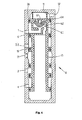
- the trailer brake valve (8) is in Fig. 2 in the valve home position and in Fig. 3 shown in the valve breakaway position.
- the red coupling head (48) is drawn in the coupled state to identify the valve's basic position.
- the pneumatic circuit diagram is in accordance with the valve home position of the piston (7), which is designed as an actuating piston for the valve, in its unactuated state and the valid for this state paths (54) are effective, so that in the trailer brake valve (8) G2) and G1) explained above [in the case that the supply pressure is applied to the port (1), the second check valve (6) explained below is operated in the forward direction].
- Fig. 3 is provided with an O-ring seal (16) actuating piston (7) with the valve spool (10) fixed and pressure-tight.
- a pressure channel (12) in the form of a blind hole In the middle of the actuating piston valve slide assembly (7, 10) is a pressure channel (12) in the form of a blind hole.
- the actuating piston (7) has a first (17) and a second (18) effective surface.
- the first active surface (17) is formed by the cross-sectional area of the actuating piston (7) and the second active surface (18) is designed as an annular surface due to the structural combination of actuating piston (7) and valve slide (10), wherein the inner ring diameter by the outer diameter of the Valve slide seal (14) is fixed.
- the first active surface (17) is designed to be larger than the second annular active surface (18).
- the second check valve (6) is installed in the effective direction shown in the actuating piston (7), wherein both active surfaces (18) and (17) are interconnected by this check valve such that the passage direction of the check valve (6) of the second (18) to the first (17) effective area extends. Since the second active surface (18) is acted upon by the pressure applied to the supply connection (1) and the first active surface (17) by the pressure applied to the container connection (3), the second check valve (6) is always then switched in the forward direction when the voltage applied to the supply connection (1) is greater than the pressure applied to the container connection (3).
- Fig. 2 In the basic position Fig. 2 is the actuating piston valve slide assembly (7, 10) by the action of the return spring (11) on the first stop (26) of the valve housing on.
- G1 and G2 are made.
- G2 represents a direct connection, ie in the pneumatic path no mechanical intermediate links are inserted [the connection G2 corresponds to the DE 28 10 850 A1 in that the pressure applied to the local control connection (7) acts first on the relay piston (6) there as a mechanical intermediate element].
- bypass channel (46) is realized as a pressure channel within the valve housing and is in the valve home position without effect, since the parking terminal (21) connected both via the direct channel (56) and via the bypass channel (46) to the same pressure chamber is, which on the in the direction of the park connection (21) opening, in the end wall of the valve spool (10) arranged first check valve (19) and the blind hole pressure channel (12) is connected to the container port (3).
- the second check valve (6) is in the reverse direction, which causes the above-mentioned compound A1).
- a pressure channel (13) is provided in the form of a bore.
- the above-described compound A2) is produced by the direct pneumatic connection from the container connection (3) via the blind-hole pressure channel (12) and the pressure channel (13) to the brake pressure connection (2).
- the park connection (21) is connected to the container connection (3) via two pneumatic connections connected in parallel.
- the first connection leads via the direct channel (56), the second check valve (19) and the blind-hole pressure channel (12 ) to the container port (3) and the second pneumatic path leads directly bypassing the check valve via the bypass channel (46), designed as a bore pressure channel (45) and the blind hole pressure channel (12) to the container port (3); when unpressurized supply connection (1) so the effect of the first check valve (19) is canceled.
- the second check valve (6) can also be carried out by the seal shown as O-ring (16) is formed as a grooved ring in a suitable mounting direction or by a check valve is provided at another location, which connects the two pressure chambers, which exert a force on the active surfaces (17) and (18).
- a suitable slide valve seal (14) as a first slide seal and to seal against the brake pressure port (2) [this seal is important in the case of the valve home position] on the valve spool (10) a slide valve seal (15) provided as a second slide seal.
- a third (43) and fourth (44) slide valve seal are provided for sealing the bore pressure channel (45).
- these slide seals serve to seal the effective in the various valve switching positions pneumatic pressure chambers for the pneumatic paths in the valve.
- the actuating piston (7) may also be integrally connected to the valve spool (10), so that the actuating piston valve spool unit (7, 10) z. B. completely as a turned part or as a plastic injection molded part can be produced.
- the slide valve seals (14, 15, 43, 44) are arranged in the valve slide (10) and the sealing surfaces on the inner wall of the valve housing
- the slide valve seals (14, 15, 43, 44) in the valve housing, above and below the bore for the brake pressure port (2) and the inlet port for the bypass passage (46) to arrange, and the sealing surfaces on the valve spool (10) form.
- the pressure prevailing in the reservoir pressure pressure now acts on both active surfaces (17) and (18) Fig. 3 one.
- the return spring (11) is dimensioned such that it overcomes the force by the surface portion by which the second active surface (18) relative to the first active surface (17) is reduced and overcompensated such that the actuating piston valve slide assembly (7, 10) is pushed by the return spring (11) to the first stop (26).
- This is the in Fig. 2 shown valve position and the brake pressure port (2) is connected to the brake specification port (4).
- the pressure chambers connected to the brake pressure port (2) ie the service brake chambers of the spring brake cylinders, are vented, so that the brake is released.
- the trailer brake valve according to the invention is designed primarily for trailer braking systems with electronic braking force control
- the device can be used in unmodified form in conventional systems, provided that the legal requirements relating to the braking time behavior are met there.
- the explained security against an automatic rolling is then effective in these systems.
- the reduced manufacturing and installation costs are also advantageous.
- the trailer brake valve according to the invention is shown in one embodiment as a slide valve, in which the slide operation depends solely on the supply port (1) pressure applied, ie in which the container connection (3) applied pressure exerts no force on the valve spool (10).
- the trailer brake valve (8) is constructed as a pressure-relieved valve, in which on the valve spool (10) of any other connection, except the supply connection (1), which acts on this force-generating effect on a below-described effective area, a compressive force is generated.
- FIG. 4 and Fig. 5 Pneumatic diagrams, as in the lower parts of Fig. 2 and Fig. 3 are shown omitted since the too Fig. 4 and Fig. 5 belonging pneumatic diagrams are basically similar to this; there is only the difference that, as explained, the valve spool (10) after Fig. 4 and Fig. 5 not actuated by the pressure difference between the supply connection (1) and the container connection (3), but switched solely by the pressure at the supply connection (1).
- valve spool (10) is formed as mentioned as a valve spool piston, ie he combines the functions of the above-described valve spool (10) and the actuating piston (7).
- the valve spool (10) is loaded with the return spring (11) and has two positions; one in Fig. 4 illustrated basic position, in which the valve slide (10) on the first stop (26) is applied, and a in Fig. 5 shown tear-off position, in which the valve spool (10) on the second stop (27) comes to rest.
- the above-explained second check valve (6) is in Fig. 4 .
- Fig. 5 realized as a grooved ring.
- a pilot valve (60) is integrated, which consists of a valve switching member (62), a force acting on the valve switching member (62) spring (61), a first valve seat (63) and a second valve seat (64).
- the pilot valve (60) has two positions, a starting position and a switching position.
- the initial position of the pilot valve (60) is in Fig. 5 In the breakaway position, no pressure is applied to the supply connection (1), and by the action of the spring (61), the valve switching element (62) abuts against the first valve seat (63), whereby the pressure space acting on the valve slide (10) is opposite to that of FIG Supply connection (1) is sealed.
- a parked trailer [demolition position Fig. 5 ] connected to the supply pressure hose (30) the pressure at the supply port (1), and according to the applied pressure and the effective diameter (65) at the first valve seat increases (63) a compressive force is exerted on the valve switching member (62).
- This effective diameter (65) determines with the properties of the spring (61) [spring length and spring constant] a pressure threshold beyond which the valve switching member (62) lifts off from the first valve seat (63).
- Fig. 6b is in the switching position of the pilot valve (60) after Fig. 6a the effective diameter (66) increases; This introduces a switching hysteresis.
- the pressure threshold z. B. expediently set to 3.5 bar.
- the explained switching hysteresis can, for. B. be designed so that the tear-off position of the trailer brake valve is taken when falling below a pressure of 2.5 bar again.
- the first valve seat (63) acts as a ventilation seat and the second valve seat (64) acts as a vent seat; during the venting of the trailer brake valve (8), ie at the transition of the valve slide (10) when the second valve seat (64) is open [64] Fig. 5 ] from the first stop (26) to the second stop (27), there is the advantage that the venting takes place directly to the atmosphere and there are no breathing spaces, as is the case with conventional trailer brake valves. Breathing rooms have the disadvantage that moisture can penetrate into the device, which may lead to icing. Compared to conventional trailer brake valves is also the advantage that the valve switching is effective immediately and not first a characteristic must be traversed.
- the pilot valve (60) is no longer integrated in the valve spool (10), but designed as a separate 3/2-way valve (70).
- the valve switching element (62) is designed as a conventional seat valve switching element, which in the tear-off position [ Fig. 8 ] at the first valve seat (63) and in the basic position [ Fig. 7 ] rests against the second valve seat (64).
- the function is similar to the embodiments according to Fig. 4 and Fig.
- Fig. 7 . 8th modified embodiment is when the check valves (6) and (19) not realized as a grooved rings in the valve spool (10), but as a separate, arranged in the housing check valves (6 ') and (19') are executed. The groove rings (6) and (19) are then replaced by corresponding O-rings.
- Fig. 7 . 8th explained Restriction that the ventilation of the reservoir pressure tank (9) takes place only after the transition of the 3/2-way valve (70) in its switching position.
- FIG. 9 The representations after Fig. 9 and Fig. 10 show the embodiment according to Fig. 7 .
- Fig. 8 in which instead of a 3/2-way valve (70) two 2/2-way valves, a first 2/2-way valve (68) as a vent valve and a second 2/2-way valve (69) are provided as a vent valve.
- the first 2/2-way valve (68) is opened, the corresponding valve switching member is lifted from the first valve seat (63), so that a ventilation through the supply connection (1) takes place;
- the second 2/2-way valve (69) is closed, the second valve seat (64) is closed, so that according to the above-described basic position function, the valve slide (10) is pushed by Duckkraft to the first stop (26).
- the second 2/2-way valve (69) is open; the opened second valve seat (64) allows venting of the valve spool (10) acting pressure chamber, so that via the return spring (11), the tear-off position on the second stop (27) is taken.
- the first 2/2-way valve (68) [first valve seat (63)] is closed, so that the pressure chamber (67), as explained above, is separated from the supply connection (1).
Landscapes
- Engineering & Computer Science (AREA)
- Transportation (AREA)
- Mechanical Engineering (AREA)
- Physics & Mathematics (AREA)
- Fluid Mechanics (AREA)
- Valves And Accessory Devices For Braking Systems (AREA)
- Braking Systems And Boosters (AREA)
- Regulating Braking Force (AREA)
Applications Claiming Priority (3)
| Application Number | Priority Date | Filing Date | Title |
|---|---|---|---|
| DE10045414 | 2000-09-14 | ||
| DE10139757A DE10139757A1 (de) | 2000-09-14 | 2001-08-13 | Anhängerbremsventil für Anhängefahrzeuge mit elektronischer Bremsregelung und erweiterter Sicherheit des geparkten Anhängers |
| EP01120604A EP1188634B2 (fr) | 2000-09-14 | 2001-08-29 | Soupape de frein de remorque pour remorques à commande de freinage électronique et à sécurité améliorée de remorque stationnée |
Related Parent Applications (1)
| Application Number | Title | Priority Date | Filing Date |
|---|---|---|---|
| EP01120604A Division EP1188634B2 (fr) | 2000-09-14 | 2001-08-29 | Soupape de frein de remorque pour remorques à commande de freinage électronique et à sécurité améliorée de remorque stationnée |
Publications (2)
| Publication Number | Publication Date |
|---|---|
| EP1914137A2 true EP1914137A2 (fr) | 2008-04-23 |
| EP1914137A3 EP1914137A3 (fr) | 2008-04-30 |
Family
ID=7656146
Family Applications (1)
| Application Number | Title | Priority Date | Filing Date |
|---|---|---|---|
| EP08002081A Withdrawn EP1914137A3 (fr) | 2000-09-14 | 2001-08-29 | Soupape de frein de remorque pour remorques à commande de freinage électronique et à sécurité améliorée du remorque stationnée |
Country Status (2)
| Country | Link |
|---|---|
| EP (1) | EP1914137A3 (fr) |
| DE (1) | DE10139757A1 (fr) |
Cited By (3)
| Publication number | Priority date | Publication date | Assignee | Title |
|---|---|---|---|---|
| WO2009046779A1 (fr) * | 2007-10-05 | 2009-04-16 | Wabco Gmbh | Modulateur de freinage de stationnement et utilisation d'un modulateur de freinage comme modulateur de freinage de stationnement |
| CN109383478A (zh) * | 2017-08-14 | 2019-02-26 | 哈尔德克斯制动产品股份公司 | 电子控制的挂车制动控制单元和挂车制动设施 |
| WO2019115030A1 (fr) * | 2017-12-13 | 2019-06-20 | Wabco Gmbh | Dispositif de soupape pneumatique pour un véhicule remorque |
Families Citing this family (7)
| Publication number | Priority date | Publication date | Assignee | Title |
|---|---|---|---|---|
| DE10248184A1 (de) * | 2002-10-16 | 2004-04-29 | Wabco Gmbh & Co. Ohg | Umschalt-Einrichtung für Anhängerbremsventil |
| DE102007002020A1 (de) * | 2007-01-13 | 2008-07-17 | Wabco Gmbh | Anhängefahrzeugbrems- und Luftfederungsanlage |
| DE102007027193A1 (de) | 2007-06-13 | 2008-12-18 | Amazonen-Werke H. Dreyer Gmbh & Co. Kg | Landwirtschaftliches Anhängefahrzeug |
| GB2462072B (en) * | 2008-07-19 | 2013-02-13 | Haldex Brake Products Ltd | Vehicle braking system |
| CN108099888A (zh) * | 2017-12-22 | 2018-06-01 | 易孝威 | 一种适应不同路况可变换气路的刹车总阀 |
| DE102019103661A1 (de) * | 2019-02-13 | 2020-08-13 | Wabco Europe Bvba | Druckluftbremsanlage eines Kraftfahrzeugs |
| EP3967562B1 (fr) * | 2020-09-11 | 2023-12-13 | Haldex Brake Products Aktiebolag | Équipement à air comprimé pour une remorque |
Citations (5)
| Publication number | Priority date | Publication date | Assignee | Title |
|---|---|---|---|---|
| DE2810850A1 (de) | 1978-03-13 | 1979-10-18 | Wabco Fahrzeugbremsen Gmbh | Anhaenger-bremsventil |
| DE3031105A1 (de) | 1980-08-16 | 1982-04-22 | Wabco Fahrzeugbremsen Gmbh, 3000 Hannover | Lastabhaengig geregelte zweileitungs-anhaengerbremsanlage |
| DE3207793C2 (fr) | 1982-03-04 | 1992-09-17 | Robert Bosch Gmbh, 7000 Stuttgart, De | |
| DE4227084A1 (de) | 1992-08-17 | 1994-02-24 | Bosch Gmbh Robert | Druckregelmodul für eine Bremsanlage, insbesondere für Nutzfahrzeuge |
| DE19818982A1 (de) | 1998-04-28 | 1999-11-18 | Knorr Bremse Systeme | Park- und Rangierventil für Anhängerfahrzeuge mit einer Federspeicher-Feststellbremse |
Family Cites Families (3)
| Publication number | Priority date | Publication date | Assignee | Title |
|---|---|---|---|---|
| US3837361A (en) * | 1971-10-26 | 1974-09-24 | Eaton Corp | Emergency control valve |
| US4002374A (en) * | 1975-05-07 | 1977-01-11 | Sloan Valve Company | Trailer air distribution valve |
| GB1552300A (en) * | 1977-01-13 | 1979-09-12 | Bendix Corp | Fluid pressure braking system having emergency valve |
-
2001
- 2001-08-13 DE DE10139757A patent/DE10139757A1/de not_active Withdrawn
- 2001-08-29 EP EP08002081A patent/EP1914137A3/fr not_active Withdrawn
Patent Citations (5)
| Publication number | Priority date | Publication date | Assignee | Title |
|---|---|---|---|---|
| DE2810850A1 (de) | 1978-03-13 | 1979-10-18 | Wabco Fahrzeugbremsen Gmbh | Anhaenger-bremsventil |
| DE3031105A1 (de) | 1980-08-16 | 1982-04-22 | Wabco Fahrzeugbremsen Gmbh, 3000 Hannover | Lastabhaengig geregelte zweileitungs-anhaengerbremsanlage |
| DE3207793C2 (fr) | 1982-03-04 | 1992-09-17 | Robert Bosch Gmbh, 7000 Stuttgart, De | |
| DE4227084A1 (de) | 1992-08-17 | 1994-02-24 | Bosch Gmbh Robert | Druckregelmodul für eine Bremsanlage, insbesondere für Nutzfahrzeuge |
| DE19818982A1 (de) | 1998-04-28 | 1999-11-18 | Knorr Bremse Systeme | Park- und Rangierventil für Anhängerfahrzeuge mit einer Federspeicher-Feststellbremse |
Cited By (5)
| Publication number | Priority date | Publication date | Assignee | Title |
|---|---|---|---|---|
| WO2009046779A1 (fr) * | 2007-10-05 | 2009-04-16 | Wabco Gmbh | Modulateur de freinage de stationnement et utilisation d'un modulateur de freinage comme modulateur de freinage de stationnement |
| CN101801745B (zh) * | 2007-10-05 | 2013-12-04 | 威伯科有限公司 | 驻车制动调节器及制动调节器作为驻车制动调节器的应用 |
| CN109383478A (zh) * | 2017-08-14 | 2019-02-26 | 哈尔德克斯制动产品股份公司 | 电子控制的挂车制动控制单元和挂车制动设施 |
| CN109383478B (zh) * | 2017-08-14 | 2022-03-01 | 哈尔德克斯制动产品股份公司 | 电子控制的挂车制动控制单元和挂车制动设施 |
| WO2019115030A1 (fr) * | 2017-12-13 | 2019-06-20 | Wabco Gmbh | Dispositif de soupape pneumatique pour un véhicule remorque |
Also Published As
| Publication number | Publication date |
|---|---|
| DE10139757A1 (de) | 2002-05-29 |
| EP1914137A3 (fr) | 2008-04-30 |
Similar Documents
| Publication | Publication Date | Title |
|---|---|---|
| EP1188634B1 (fr) | Soupape de frein de remorque pour remorques à commande de freinage électronique et à sécurité améliorée de remorque stationnée | |
| EP3600996B1 (fr) | Module integre pour remorque avec unité externe de freinage de stationnement electro-pneumatique | |
| EP3600991B1 (fr) | Frein à main électro-pneumatique avec tcv integré (commande scandinave) | |
| EP2059429B1 (fr) | Unité de soupape pour dispositif de commande de freinage électropneumatique | |
| EP2567874B1 (fr) | Composant de soupape pour une installation de freinage d'une remorque | |
| DE102007038472B4 (de) | Ventilanordnung zur Steuerung einer Bremsanlage eines Anhängerfahrzeugs | |
| DE102012101871B4 (de) | Parkbremsventileinrichtung und pneumatische Anhänger-Druckluftbremsanlage | |
| EP2757010B1 (fr) | Système de soupape pour une installation d'air comprimé d'une remorque de véhicule utilitaire | |
| EP3515770B1 (fr) | Arrangement de vannes de frein de stationnement pour commander un frein d'immobilisation à ressort accumulateur | |
| EP2426021B1 (fr) | Soupape de stationnement pour une remorque de véhicule utilitaire | |
| DE102017006356A1 (de) | Elektro-Pneumatische Handbremse (EPH) mit integriertem TCV (Europäische Ansteuerung) | |
| EP2058186A2 (fr) | Installation de frein pour une remorque d'un véhicule automobile | |
| EP3626564B1 (fr) | Soupape de commande, système de freinage à commande électronique ainsi que procédé de commande du système de freinage à commande électronique | |
| DE102013100538B4 (de) | Druckluftanlage eines Anhängers eines Nutzfahrzeugs | |
| EP0957018B1 (fr) | Régulateur de pression pour installations de production d'air comprimé dans de véhicules | |
| DE19918070B4 (de) | Druckregelvorrichtung für elektro-pneumatische Bremsanlagen von Fahrzeugen, insbesondere Nutzfahrzeugen | |
| EP3784540B1 (fr) | Soupape de commande, système de freinage à commande électronique et procédé de commande du système de freinage à commande électronique | |
| EP3626563A1 (fr) | Soupape de commande, système de freinage à commande électronique ainsi que procédé de commande du système de freinage à commande électronique | |
| DE20122549U1 (de) | Anhängerbremsventil für Anhängefahrzeuge mit elektronischer Bremsregelung und erweiterter Sicherheit des geparkten Anhängers | |
| EP1914137A2 (fr) | Soupape de frein de remorque pour remorques à commande de freinage électronique et à sécurité améliorée du remorque stationnée | |
| EP0378810B1 (fr) | Installation de freinage à air comprimé pour véhicules à moteur | |
| EP0829406B1 (fr) | Installation de frein à deux conduites pour remorque | |
| EP1069015A2 (fr) | Installation de freinage actionnée par moyen de pression | |
| DE20122779U1 (de) | Anhängerbremsventil für Anhängefahrzeuge mit elektronischer Bremsregelung und erweiterter Sicherheit des geparkten Anhängers | |
| DE10139748A1 (de) | Anhängerbremsventil für einen Anhänger mit elektronischer Bremsregelung |
Legal Events
| Date | Code | Title | Description |
|---|---|---|---|
| PUAI | Public reference made under article 153(3) epc to a published international application that has entered the european phase |
Free format text: ORIGINAL CODE: 0009012 |
|
| PUAL | Search report despatched |
Free format text: ORIGINAL CODE: 0009013 |
|
| AC | Divisional application: reference to earlier application |
Ref document number: 1188634 Country of ref document: EP Kind code of ref document: P |
|
| AK | Designated contracting states |
Kind code of ref document: A2 Designated state(s): DE ES FR GB IT SE |
|
| AK | Designated contracting states |
Kind code of ref document: A3 Designated state(s): DE ES FR GB IT SE |
|
| 17P | Request for examination filed |
Effective date: 20081030 |
|
| 17Q | First examination report despatched |
Effective date: 20081127 |
|
| AKX | Designation fees paid |
Designated state(s): DE ES FR GB IT SE |
|
| STAA | Information on the status of an ep patent application or granted ep patent |
Free format text: STATUS: THE APPLICATION HAS BEEN WITHDRAWN |
|
| 18W | Application withdrawn |
Effective date: 20111206 |