EP1914376A2 - Habillage de porte roulante ou de grille roulante ainsi que porte roulante ou grille roulante en étant équipé - Google Patents
Habillage de porte roulante ou de grille roulante ainsi que porte roulante ou grille roulante en étant équipé Download PDFInfo
- Publication number
- EP1914376A2 EP1914376A2 EP07115997A EP07115997A EP1914376A2 EP 1914376 A2 EP1914376 A2 EP 1914376A2 EP 07115997 A EP07115997 A EP 07115997A EP 07115997 A EP07115997 A EP 07115997A EP 1914376 A2 EP1914376 A2 EP 1914376A2
- Authority
- EP
- European Patent Office
- Prior art keywords
- winding shaft
- flexible
- cover
- cladding according
- support structure
- Prior art date
- Legal status (The legal status is an assumption and is not a legal conclusion. Google has not performed a legal analysis and makes no representation as to the accuracy of the status listed.)
- Withdrawn
Links
- 238000005096 rolling process Methods 0.000 title claims description 18
- 238000004804 winding Methods 0.000 claims abstract description 49
- 239000004753 textile Substances 0.000 claims abstract description 21
- 239000004744 fabric Substances 0.000 claims abstract description 14
- 239000012780 transparent material Substances 0.000 claims abstract 2
- 238000005253 cladding Methods 0.000 claims description 27
- 230000004888 barrier function Effects 0.000 abstract 1
- 208000027418 Wounds and injury Diseases 0.000 description 11
- 238000005553 drilling Methods 0.000 description 3
- 238000003780 insertion Methods 0.000 description 2
- 230000037431 insertion Effects 0.000 description 2
- 238000012423 maintenance Methods 0.000 description 2
- 229910000831 Steel Inorganic materials 0.000 description 1
- 238000010276 construction Methods 0.000 description 1
- 230000006378 damage Effects 0.000 description 1
- 230000001419 dependent effect Effects 0.000 description 1
- 238000001514 detection method Methods 0.000 description 1
- 239000011152 fibreglass Substances 0.000 description 1
- 208000014674 injury Diseases 0.000 description 1
- 238000009434 installation Methods 0.000 description 1
- 239000002184 metal Substances 0.000 description 1
- 238000000034 method Methods 0.000 description 1
- 230000003287 optical effect Effects 0.000 description 1
- 239000002985 plastic film Substances 0.000 description 1
- 238000003825 pressing Methods 0.000 description 1
- 238000009958 sewing Methods 0.000 description 1
- 239000010959 steel Substances 0.000 description 1
- 239000003351 stiffener Substances 0.000 description 1
Images


Classifications
-
- E—FIXED CONSTRUCTIONS
- E06—DOORS, WINDOWS, SHUTTERS, OR ROLLER BLINDS IN GENERAL; LADDERS
- E06B—FIXED OR MOVABLE CLOSURES FOR OPENINGS IN BUILDINGS, VEHICLES, FENCES OR LIKE ENCLOSURES IN GENERAL, e.g. DOORS, WINDOWS, BLINDS, GATES
- E06B9/00—Screening or protective devices for wall or similar openings, with or without operating or securing mechanisms; Closures of similar construction
- E06B9/02—Shutters, movable grilles, or other safety closing devices, e.g. against burglary
- E06B9/08—Roll-type closures
- E06B9/11—Roller shutters
- E06B9/17—Parts or details of roller shutters, e.g. suspension devices, shutter boxes, wicket doors, ventilation openings
- E06B9/17007—Shutter boxes; Details or component parts thereof
Definitions
- the invention relates to a covering for a roller shutter or a rolling grill. Furthermore, the invention relates to a rolling shutter provided with such a cover or rolling grille.
- Roller shutters or rolling grilles generally have a winding shaft to be mounted in the region of a fall of an opening to be closed and a curtain which can be wound up thereon.
- the curtain is, for example, in the form of a roller door, a roller blind or in the form of a flexible curtain.
- a Rolltorpanzer is formed from a series hinged to each other hinged Rolltorprofile. The profiles are often made of metal, such as steel.
- a Gitterbehang is formed for example of articulated to each other attached grid elements.
- Flexible Rolltorbe-13 are constructed for example of plastic sheets. Such flexible Rolltorbe-13 be used especially in high-speed doors.
- roller doors which are to close building openings with a height of 2500 mm or smaller
- people can reach the winding shaft and winding up on the winding shaft blind with his hands. If one intervenes when winding the roller table curtain between winding shaft and curtain, then the hand could be trapped by the winding up hangings.
- a rolltorbehanges there is also a possible possibility that fingers are trapped between Rolltorprofilen that move relative to each other in the course of winding or unwinding of Rolltorpanzers.
- the building opening is larger than about 2500 mm, the risk that persons who can usually reach the winding shaft located above the building opening or the drapery area wound thereon is extremely low.
- Roll-up doors for such high building openings can therefore be thought-free simply constructed so that the winding shaft is mounted on corresponding bearings otherwise freely accessible in the fall above the building opening. If there is any problem with the roll-up door when winding or unwinding, you can immediately see the problem visually and take appropriate countermeasures.
- the invention has for its object to provide a device that eliminates the risk of injury to rolling doors without disadvantages for installation and operability and error detection.
- a cladding for a roller shutter or a rolling grille which has a winding shaft and a wound on the winding shaft, designed to close a building opening curtain.
- This fairing serves to the winding shaft at least partially to cover so that protection against interference with moving parts during winding (or possibly also when unwinding) of the curtain is given.
- the cladding has a flexible cover and a support structure for the flexible cover.
- the flexible cover has at least one flexible web.
- a flexible track can be supplemented by side panels to avoid intervention from the side.
- the side panel can be made flexible.
- the flexible cover may be in the form of a hood.
- a hood practically forms a cover in which a flexible sheet for protection against radial direction engagement and a side cover for protection against engagement from the axial direction are combined in a single cover.
- the use of a flexible cover, in particular for the lining of winding shafts against engagement, has the considerable advantage that the flexible web can be used for very different sizes and diameters and can be transported and mounted very easily to the place of use. Nevertheless, such a flexible track is completely sufficient for protection against intervention.
- the support structure serves to attach and possibly stiffen the flexible cover. This can be avoided, for example, a grinding of the cover on movable elements of the roll-up door. In particular, it can be avoided that hands or fingers can still be clamped together with the cover in parts of the rolling door by pressing in the flexible cover.
- a support structure can facilitate the mounting of the cover considerably.
- the cladding is at least partially transparent, so that any problems on the winding shaft covered by the cladding can continue to be visually recognized.
- optical recognition of problems is also partly due to the flexibility of the cover achievable because, for example, an improperly wound curtain can stand against the flexible cover and thus change their shape, which would also indicate problems.
- the flexible cover is formed from a textile fabric.
- the textile fabric may be so coarse that it is transparent to recognize the covered roller door construction behind it.
- the fabric may be in the form of a net.
- the support structure may be designed for clamping the textile fabric.
- a flexible cover can be easily fold and / or wind up in the event that you want to access, for example, for maintenance purposes or repair purposes on the winding shaft and / or the wrapped curtain, and thus does not need to be removed in this case.
- a stiffening structure may be provided, which, for example, stiffens the flexible cover, in particular the web, of the covering in at least one direction.
- the flexible web is stiffened in the axial direction of the winding shaft, so that they can not be folded back from the axial ends of the winding shafts or very difficult, but a rolling or folding back in the circumferential direction or in the radial direction relative to the shaft is easily possible.
- the support structure can be designed very different. Conceivable would be supporting structures, as they are also used in different known tent structures.
- the support structure could have flexible rod elements, which are clamped accordingly.
- the support structure is provided with a plurality of bracket elements, at least at one end, for example, the fall are fastened and designed to encompass the winding shaft.
- the brackets are preferably designed such that between the winding shaft and the bracket sufficient space for receiving the wound roller blind curtain is maintained.
- the plurality of brackets are interconnected by at least one rod member, which preferably extends substantially parallel to the axial direction of the winding shaft, for stiffening the support structure.
- the mounting bracket can be individually attached to brackets.
- a fastening strip or other common fastening device may be provided, to which the ends of a plurality of mounting brackets are fastened together.
- at least two attachment regions are further preferably formed on the flexible cover.
- the above-mentioned stiffening structure may have a profiled strip or pipe strip, which may also be provided with fastening elements, for example screw holes or hook-and-loop fasteners or the like, with which the flexible cover can be fastened to the supporting structure or to a wall holding the supporting structure, for example the lintel wall.
- the flexible cover could also be wound around this profiled strip / tube strip for transport and / or in case of maintenance.
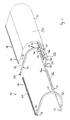
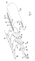
- Fig. 1 is a side view of a roll end 10 for closing a building opening 12 is shown.
- the roll closure 10 has a winding shaft 14 and a curtain 16 which can be wound up thereon.
- the roll closure is designed in the form of a roll-up door 18, the curtain 16 being designed as a roll-up door 20.
- the roll cover 10 could also be formed in the form of a rolling grid with a wound onto the winding shaft 14 grid as curtain 16.
- the winding shaft 14 is rotatably mounted in a manner not shown in the region of a lintel 24 above the building opening 12 driven by a motor.
- the curtain 16 is guided in lateral guide rails 25.
- a cladding 22 is provided for protection against interference with moving parts of the roll termination 10.
- the panel 22 is attached to the lintel 24 and engages around the winding shaft 14 and the curtain 16 wound thereon for the most part; Only in the lower region between the lintel 24 and the cladding 22 is a slot 26 for the unwound region 28 of the curtain 16 is formed.
- the cladding 22 has a support structure 30 and a cover, here in the form of a flexible web 32 held on this support structure 30.
- the flexible web 32 has a textile fabric in the form of a textile net 34. Through the stitches of the textile mesh 34, the flexible sheet 32 is transparent, so that you can see the underneath winding shaft 14 with the wrapped curtain 16 in plan view of the panel.
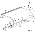
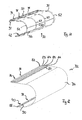
- a first embodiment of the lining 22 is explained in more detail below with reference to FIGS. 2 to 9.
- the flexible web 32 has a first fastening device 38 in the region of a first long edge 36 and a second fastening device 42 in the region of the second long edge 40 parallel to the first long edge 36.
- first fastening device 38 the first long edge 36 is formed with such a structure that it can be pulled into a welt strip 44 of the support structure 30.
- second fastening device a Velcro connection 46 is formed in the region of the second long edge 40 in such a manner that an end region 48 can be formed to form a loop 50 and fastened to the remaining region of the flexible web 32 by means of the Velcro connection 46.
- the support structure 30 of the first embodiment comprises a plurality of rectangular tubes formed bracket 52 which are fastened by means of fastening brackets 54 to the lintel 24, and which can be connected to each other by means of tubular rods 56, 56 a and 44 by means of the Kedermann. Between two adjacent brackets 52 two pipe rods 56 and 56a are respectively provided, wherein a first pipe rod 56 is inserted in the region of the respective free end 58 provided there corresponding holes 60 and wherein a second pipe rod 56a provided in a vertex portion 62 of the bracket 52 in there Holes 64 is inserted.
- the first long edge 36 of the web 32 is inserted into the welt strip 44.
- the end region 48 is placed around the first tube rod 56 and then fastened with the Velcro connection 46.
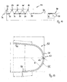
- each bracket 52 accordingly has a first end 66 formed for attachment to the mounting bracket 54, a bent portion 68 having the apex portion 62 and the already mentioned free end 58.
- the two Ends 66, 58 each have an approximately straight extension, which is formed at the first end 66 longer than at the free end 58, so as to ensure the slot 26 at the free end 58.
- the rounding and the radius of the bent region 38 is selected such that it can still surround the winding shaft 14 and the area of the curtain 16 wound around the winding shaft in the fully opened state of the roll end 10 at a distance.
- a plurality of holes 70 for fastening screws 72 are formed, which serve in addition to the attachment of the flexible sheet 32 by means of the Kedermann 44 and the Velcro connection 46 for fastening the flexible sheet 32.
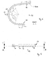
- the mounting bracket 54 has a mounting plate 74 with two openings 76 for wall fasteners (not shown) and a protruding from the mounting plate 54 engaging tube 78. Through the openings 76, the mounting bracket 54 in particular by means of screw-dowel fasteners (not shown) to the lintel 24 can be fastened.
- the engagement tube 78 has in this embodiment, as the bracket 52, a square profile and is formed such that the first end 66 of the bracket 52 can be rotationally fitted to the engaging tube 78. This connector can still be secured in a manner not shown by pins, screws or the like.
- the welt strip 44 is also attached to the wall of the lintel 24, so that the first fastening device 38 is only indirectly connected via the lintel 24 with the support structure 30.
- the welt strip 44 and the pipe bar 56 serve as stiffening structures that stiffen the flexible web 32 in the direction approximately parallel to the axis of the winding shaft 14.
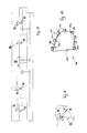
- FIGS. 10 to 18 also show a second embodiment of the lining 22, which likewise has the support structure 30 and the flexible cover with the flexible web 32.
- the same reference numerals as in the first embodiment are used for corresponding parts.
- the first fastening device 38 of the flexible web 32 is formed in that the end region 48 has been turned over and is sewn to a plurality of line-like seam regions 80, which are arranged at a distance from one another, such that a loop is formed between the linear seam regions 80 82-86 is formed.
- the second fastener 42 is formed by a single loop 88 and the stitching 90.
- adhesions can be made or any other conceivable attachment (for example, riveting, pinching between two fastened areas, fastening with snaps, zippers and the like).
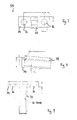
- the support structure 30 of the second embodiment differs from the support structure of the first embodiment in particular in that instead of the plurality of mounting brackets 54, a common Befest Trentsleite 92 is provided with a plurality of the engagement tubes 78. Further, in addition to the pipe bars 56 and 56a at the free ends 58 of the bracket 52 and the apex portion 62 of the bracket 52 is still a third rod member in the form of a third tubular rod 94 is provided which can be pushed by attached to the mounting rail 92 eyelets 96.
- the procedure initially such that the pipe rod 56 is pushed at the free ends of the bracket 52 through the loop 88 of the second fastening device 42.
- This loop 88 is interrupted at the locations of the bracket 52 through slots 98.
- plug-in elements 100 with an eyelet portion 102 and a male portion 104, wherein the third tube rod 94 is guided through the eyelet portions 102 and the insertion portion 104 is inserted respectively into the free end 58 of the respective bracket 52.
- the flexible web 32 is then passed around the stirrups and around the second pipe bar 56 a provided at the apex regions 62 of the stirrups 52 and fastened to the fastening bar 92 by means of the third pipe bar 94.
- the third pipe rod 94 is inserted into that of the loops 82-86, which ensures a suitable tensioning of the flexible web 32.
- This loop 82 is then provided with the slots 98 for inserting the eyelets 96.
- the degree of tension of the flexible web 32 can be selected.
- FIG. 19 also shows a side panel 106 which can be used in both illustrated embodiments.
- the side trim 106 like the flexible web 32, is made from a textile fabric 108 and forms an additional part of the flexible cover.
- the side cover 106 can be fastened with a fastening device 110 to the respectively provided at the lateral ends bracket 52.
- the fastening device 110 has a cap 112, which can be pushed onto the free end 58 of the bracket 52.
- the cap 112 is closed at the intended use of the building opening 12 towards the end, so that the cap 112 is supported at the free end 58.
- the fastening device 110 a plurality of loops 120, one end of which is fixedly connected to the surface portion of the textile fabric 108 and the other end by means of a Velcro connection 122 on the flat piece of textile fabric 108 can be fastened.
- a stiffener 124 for example in the form of a rod made of fiberglass reinforced plastic, be present.
- the side panel 106 is integrally formed with the flexible sheet 32 in an embodiment, not shown.
- the flexible cover is designed in the form of a hood made of textile fabric.
Landscapes
- Engineering & Computer Science (AREA)
- Structural Engineering (AREA)
- Architecture (AREA)
- Civil Engineering (AREA)
- Operating, Guiding And Securing Of Roll- Type Closing Members (AREA)
Applications Claiming Priority (2)
| Application Number | Priority Date | Filing Date | Title |
|---|---|---|---|
| DE102006048994 | 2006-10-17 | ||
| DE102006050595A DE102006050595B4 (de) | 2006-10-17 | 2006-10-26 | Verkleidung für einen Rollabschluss, insbesondere Rolltor oder ein Rollgitter, sowie damit versehene Rollabschlussvorrichtung |
Publications (2)
| Publication Number | Publication Date |
|---|---|
| EP1914376A2 true EP1914376A2 (fr) | 2008-04-23 |
| EP1914376A3 EP1914376A3 (fr) | 2011-09-28 |
Family
ID=39047905
Family Applications (1)
| Application Number | Title | Priority Date | Filing Date |
|---|---|---|---|
| EP07115997A Withdrawn EP1914376A3 (fr) | 2006-10-17 | 2007-09-10 | Habillage de porte roulante ou de grille roulante ainsi que porte roulante ou grille roulante en étant équipé |
Country Status (2)
| Country | Link |
|---|---|
| EP (1) | EP1914376A3 (fr) |
| DE (1) | DE102006050595B4 (fr) |
Cited By (3)
| Publication number | Priority date | Publication date | Assignee | Title |
|---|---|---|---|---|
| JP2015048679A (ja) * | 2013-09-03 | 2015-03-16 | 文化シヤッター株式会社 | 開閉体収容ケース |
| CN108979503A (zh) * | 2017-06-02 | 2018-12-11 | 安徽朝迅教育管理咨询有限公司 | 一种具有溶噪罩壳的电动卷挂装置 |
| CN109061994A (zh) * | 2017-06-02 | 2018-12-21 | 安徽朝迅教育管理咨询有限公司 | 一种低振低噪的电动卷挂装置 |
Citations (3)
| Publication number | Priority date | Publication date | Assignee | Title |
|---|---|---|---|---|
| US5044131A (en) | 1990-05-18 | 1991-09-03 | Fisher Larry M | Fabric awning assembly and divider bead for use therein |
| JPH0666074A (ja) | 1992-01-28 | 1994-03-08 | Nichibei Co Ltd | ロ−ルスクリ−ン |
| FR2842243A1 (fr) | 2002-07-12 | 2004-01-16 | Nergeco Sa | Porte etanche |
Family Cites Families (3)
| Publication number | Priority date | Publication date | Assignee | Title |
|---|---|---|---|---|
| DE1831390U (de) * | 1961-02-27 | 1961-05-18 | Erich Schlenker | Rolladenkasten. |
| DE20018706U1 (de) * | 2000-11-02 | 2002-03-07 | Warema Renkhoff Gmbh, 97828 Marktheidenfeld | Vorbau-Rolladenkasten |
| FR2892759B1 (fr) * | 2005-10-28 | 2008-02-01 | Nergeco Sa | Porte rapide a rideau souple |
-
2006
- 2006-10-26 DE DE102006050595A patent/DE102006050595B4/de not_active Expired - Fee Related
-
2007
- 2007-09-10 EP EP07115997A patent/EP1914376A3/fr not_active Withdrawn
Patent Citations (3)
| Publication number | Priority date | Publication date | Assignee | Title |
|---|---|---|---|---|
| US5044131A (en) | 1990-05-18 | 1991-09-03 | Fisher Larry M | Fabric awning assembly and divider bead for use therein |
| JPH0666074A (ja) | 1992-01-28 | 1994-03-08 | Nichibei Co Ltd | ロ−ルスクリ−ン |
| FR2842243A1 (fr) | 2002-07-12 | 2004-01-16 | Nergeco Sa | Porte etanche |
Cited By (3)
| Publication number | Priority date | Publication date | Assignee | Title |
|---|---|---|---|---|
| JP2015048679A (ja) * | 2013-09-03 | 2015-03-16 | 文化シヤッター株式会社 | 開閉体収容ケース |
| CN108979503A (zh) * | 2017-06-02 | 2018-12-11 | 安徽朝迅教育管理咨询有限公司 | 一种具有溶噪罩壳的电动卷挂装置 |
| CN109061994A (zh) * | 2017-06-02 | 2018-12-21 | 安徽朝迅教育管理咨询有限公司 | 一种低振低噪的电动卷挂装置 |
Also Published As
| Publication number | Publication date |
|---|---|
| DE102006050595A1 (de) | 2008-04-24 |
| EP1914376A3 (fr) | 2011-09-28 |
| DE102006050595B4 (de) | 2013-02-21 |
Similar Documents
| Publication | Publication Date | Title |
|---|---|---|
| EP1010559B1 (fr) | Store roulant pour véhicule automobile | |
| DE202008016773U1 (de) | Abdeckung für ein gekipptes oder geöffnetes Fenster | |
| EP0426046B1 (fr) | Moustiquaire-grille à rouleau | |
| EP1914376A2 (fr) | Habillage de porte roulante ou de grille roulante ainsi que porte roulante ou grille roulante en étant équipé | |
| EP2826945B1 (fr) | Pare-soleil vertical | |
| DE102013100093A1 (de) | Insekten- und/oder Pollenschutzvorrichtung | |
| DE202023105641U1 (de) | Behang und Behangsystem mit einem Behang | |
| EP0335177B1 (fr) | Dispositif pour l'occultation de fenêtres | |
| DE10316785B4 (de) | Rollovorrichtung | |
| EP2939713B1 (fr) | Rideau pare-feu | |
| DE102013003012A1 (de) | Flächenvorhangsystem | |
| DE69717953T2 (de) | Befestigungsvorrichtung für Schiebepaneel | |
| DE19903008C2 (de) | Rolladen | |
| DE3925801C2 (de) | Fensterrollo für eine nicht-rechteckige Kraftfahrzeug-Fensterscheibe | |
| DE102007002857B4 (de) | Rolloanordnung mit Führungselement | |
| DE1659463A1 (de) | Rafflamellenstore | |
| DE102015000170A1 (de) | Raffstore | |
| DE102010017729A1 (de) | Sicht- und Sonnenschutz für Markisen | |
| DE8912903U1 (de) | Insektenschutz-Rollgittervorrichtung | |
| DE2527382C3 (de) | Schutzabdeckung für verschwenkbare Dachflächenfenster | |
| DE10257512A1 (de) | Raffvorhang | |
| EP2067909A1 (fr) | Dispositif d'ombrage | |
| EP3228801B1 (fr) | Ombrage vertical avec consoles de fixation réglables | |
| DE1074253B (de) | FaIt laden | |
| DE20103970U1 (de) | Dekorationssystem für Fenster, Türen o.dgl. |
Legal Events
| Date | Code | Title | Description |
|---|---|---|---|
| PUAI | Public reference made under article 153(3) epc to a published international application that has entered the european phase |
Free format text: ORIGINAL CODE: 0009012 |
|
| AK | Designated contracting states |
Kind code of ref document: A2 Designated state(s): AT BE BG CH CY CZ DE DK EE ES FI FR GB GR HU IE IS IT LI LT LU LV MC MT NL PL PT RO SE SI SK TR |
|
| AX | Request for extension of the european patent |
Extension state: AL BA HR MK RS |
|
| PUAL | Search report despatched |
Free format text: ORIGINAL CODE: 0009013 |
|
| AK | Designated contracting states |
Kind code of ref document: A3 Designated state(s): AT BE BG CH CY CZ DE DK EE ES FI FR GB GR HU IE IS IT LI LT LU LV MC MT NL PL PT RO SE SI SK TR |
|
| AX | Request for extension of the european patent |
Extension state: AL BA HR MK RS |
|
| RIC1 | Information provided on ipc code assigned before grant |
Ipc: E06B 9/17 20060101AFI20110823BHEP |
|
| 17P | Request for examination filed |
Effective date: 20120328 |
|
| AKX | Designation fees paid |
Designated state(s): AT CH DE LI |
|
| STAA | Information on the status of an ep patent application or granted ep patent |
Free format text: STATUS: THE APPLICATION IS DEEMED TO BE WITHDRAWN |
|
| 18D | Application deemed to be withdrawn |
Effective date: 20130403 |