EP1914399A1 - Abgasreinigungsvorrichtung - Google Patents
Abgasreinigungsvorrichtung Download PDFInfo
- Publication number
- EP1914399A1 EP1914399A1 EP06386031A EP06386031A EP1914399A1 EP 1914399 A1 EP1914399 A1 EP 1914399A1 EP 06386031 A EP06386031 A EP 06386031A EP 06386031 A EP06386031 A EP 06386031A EP 1914399 A1 EP1914399 A1 EP 1914399A1
- Authority
- EP
- European Patent Office
- Prior art keywords
- particulate filter
- diesel particulate
- exhaust gas
- primary
- exhaust line
- Prior art date
- Legal status (The legal status is an assumption and is not a legal conclusion. Google has not performed a legal analysis and makes no representation as to the accuracy of the status listed.)
- Granted
Links
Images





Classifications
-
- F—MECHANICAL ENGINEERING; LIGHTING; HEATING; WEAPONS; BLASTING
- F01—MACHINES OR ENGINES IN GENERAL; ENGINE PLANTS IN GENERAL; STEAM ENGINES
- F01N—GAS-FLOW SILENCERS OR EXHAUST APPARATUS FOR MACHINES OR ENGINES IN GENERAL; GAS-FLOW SILENCERS OR EXHAUST APPARATUS FOR INTERNAL-COMBUSTION ENGINES
- F01N3/00—Exhaust or silencing apparatus having means for purifying, rendering innocuous, or otherwise treating exhaust
- F01N3/02—Exhaust or silencing apparatus having means for purifying, rendering innocuous, or otherwise treating exhaust for cooling, or for removing solid constituents of, exhaust
- F01N3/021—Exhaust or silencing apparatus having means for purifying, rendering innocuous, or otherwise treating exhaust for cooling, or for removing solid constituents of, exhaust by means of filters
-
- F—MECHANICAL ENGINEERING; LIGHTING; HEATING; WEAPONS; BLASTING
- F01—MACHINES OR ENGINES IN GENERAL; ENGINE PLANTS IN GENERAL; STEAM ENGINES
- F01N—GAS-FLOW SILENCERS OR EXHAUST APPARATUS FOR MACHINES OR ENGINES IN GENERAL; GAS-FLOW SILENCERS OR EXHAUST APPARATUS FOR INTERNAL-COMBUSTION ENGINES
- F01N3/00—Exhaust or silencing apparatus having means for purifying, rendering innocuous, or otherwise treating exhaust
- F01N3/02—Exhaust or silencing apparatus having means for purifying, rendering innocuous, or otherwise treating exhaust for cooling, or for removing solid constituents of, exhaust
- F01N3/021—Exhaust or silencing apparatus having means for purifying, rendering innocuous, or otherwise treating exhaust for cooling, or for removing solid constituents of, exhaust by means of filters
- F01N3/022—Exhaust or silencing apparatus having means for purifying, rendering innocuous, or otherwise treating exhaust for cooling, or for removing solid constituents of, exhaust by means of filters characterised by specially adapted filtering structure, e.g. honeycomb, mesh or fibrous
- F01N3/0222—Exhaust or silencing apparatus having means for purifying, rendering innocuous, or otherwise treating exhaust for cooling, or for removing solid constituents of, exhaust by means of filters characterised by specially adapted filtering structure, e.g. honeycomb, mesh or fibrous the structure being monolithic, e.g. honeycombs
-
- F—MECHANICAL ENGINEERING; LIGHTING; HEATING; WEAPONS; BLASTING
- F01—MACHINES OR ENGINES IN GENERAL; ENGINE PLANTS IN GENERAL; STEAM ENGINES
- F01N—GAS-FLOW SILENCERS OR EXHAUST APPARATUS FOR MACHINES OR ENGINES IN GENERAL; GAS-FLOW SILENCERS OR EXHAUST APPARATUS FOR INTERNAL-COMBUSTION ENGINES
- F01N11/00—Monitoring or diagnostic devices for exhaust-gas treatment apparatus
- F01N11/002—Monitoring or diagnostic devices for exhaust-gas treatment apparatus the diagnostic devices measuring or estimating temperature or pressure in, or downstream of the exhaust apparatus
-
- F—MECHANICAL ENGINEERING; LIGHTING; HEATING; WEAPONS; BLASTING
- F01—MACHINES OR ENGINES IN GENERAL; ENGINE PLANTS IN GENERAL; STEAM ENGINES
- F01N—GAS-FLOW SILENCERS OR EXHAUST APPARATUS FOR MACHINES OR ENGINES IN GENERAL; GAS-FLOW SILENCERS OR EXHAUST APPARATUS FOR INTERNAL-COMBUSTION ENGINES
- F01N13/00—Exhaust or silencing apparatus characterised by constructional features
- F01N13/008—Mounting or arrangement of exhaust sensors in or on exhaust apparatus
-
- F—MECHANICAL ENGINEERING; LIGHTING; HEATING; WEAPONS; BLASTING
- F01—MACHINES OR ENGINES IN GENERAL; ENGINE PLANTS IN GENERAL; STEAM ENGINES
- F01N—GAS-FLOW SILENCERS OR EXHAUST APPARATUS FOR MACHINES OR ENGINES IN GENERAL; GAS-FLOW SILENCERS OR EXHAUST APPARATUS FOR INTERNAL-COMBUSTION ENGINES
- F01N13/00—Exhaust or silencing apparatus characterised by constructional features
- F01N13/011—Exhaust or silencing apparatus characterised by constructional features having two or more purifying devices arranged in parallel
-
- F—MECHANICAL ENGINEERING; LIGHTING; HEATING; WEAPONS; BLASTING
- F01—MACHINES OR ENGINES IN GENERAL; ENGINE PLANTS IN GENERAL; STEAM ENGINES
- F01N—GAS-FLOW SILENCERS OR EXHAUST APPARATUS FOR MACHINES OR ENGINES IN GENERAL; GAS-FLOW SILENCERS OR EXHAUST APPARATUS FOR INTERNAL-COMBUSTION ENGINES
- F01N13/00—Exhaust or silencing apparatus characterised by constructional features
- F01N13/08—Other arrangements or adaptations of exhaust conduits
-
- F—MECHANICAL ENGINEERING; LIGHTING; HEATING; WEAPONS; BLASTING
- F01—MACHINES OR ENGINES IN GENERAL; ENGINE PLANTS IN GENERAL; STEAM ENGINES
- F01N—GAS-FLOW SILENCERS OR EXHAUST APPARATUS FOR MACHINES OR ENGINES IN GENERAL; GAS-FLOW SILENCERS OR EXHAUST APPARATUS FOR INTERNAL-COMBUSTION ENGINES
- F01N3/00—Exhaust or silencing apparatus having means for purifying, rendering innocuous, or otherwise treating exhaust
- F01N3/02—Exhaust or silencing apparatus having means for purifying, rendering innocuous, or otherwise treating exhaust for cooling, or for removing solid constituents of, exhaust
- F01N3/021—Exhaust or silencing apparatus having means for purifying, rendering innocuous, or otherwise treating exhaust for cooling, or for removing solid constituents of, exhaust by means of filters
- F01N3/023—Exhaust or silencing apparatus having means for purifying, rendering innocuous, or otherwise treating exhaust for cooling, or for removing solid constituents of, exhaust by means of filters using means for regenerating the filters, e.g. by burning trapped particles
-
- F—MECHANICAL ENGINEERING; LIGHTING; HEATING; WEAPONS; BLASTING
- F01—MACHINES OR ENGINES IN GENERAL; ENGINE PLANTS IN GENERAL; STEAM ENGINES
- F01N—GAS-FLOW SILENCERS OR EXHAUST APPARATUS FOR MACHINES OR ENGINES IN GENERAL; GAS-FLOW SILENCERS OR EXHAUST APPARATUS FOR INTERNAL-COMBUSTION ENGINES
- F01N3/00—Exhaust or silencing apparatus having means for purifying, rendering innocuous, or otherwise treating exhaust
- F01N3/02—Exhaust or silencing apparatus having means for purifying, rendering innocuous, or otherwise treating exhaust for cooling, or for removing solid constituents of, exhaust
- F01N3/021—Exhaust or silencing apparatus having means for purifying, rendering innocuous, or otherwise treating exhaust for cooling, or for removing solid constituents of, exhaust by means of filters
- F01N3/023—Exhaust or silencing apparatus having means for purifying, rendering innocuous, or otherwise treating exhaust for cooling, or for removing solid constituents of, exhaust by means of filters using means for regenerating the filters, e.g. by burning trapped particles
- F01N3/027—Exhaust or silencing apparatus having means for purifying, rendering innocuous, or otherwise treating exhaust for cooling, or for removing solid constituents of, exhaust by means of filters using means for regenerating the filters, e.g. by burning trapped particles using electric or magnetic heating means
-
- F—MECHANICAL ENGINEERING; LIGHTING; HEATING; WEAPONS; BLASTING
- F01—MACHINES OR ENGINES IN GENERAL; ENGINE PLANTS IN GENERAL; STEAM ENGINES
- F01N—GAS-FLOW SILENCERS OR EXHAUST APPARATUS FOR MACHINES OR ENGINES IN GENERAL; GAS-FLOW SILENCERS OR EXHAUST APPARATUS FOR INTERNAL-COMBUSTION ENGINES
- F01N9/00—Electrical control of exhaust gas treating apparatus
- F01N9/002—Electrical control of exhaust gas treating apparatus of filter regeneration
-
- G—PHYSICS
- G01—MEASURING; TESTING
- G01N—INVESTIGATING OR ANALYSING MATERIALS BY DETERMINING THEIR CHEMICAL OR PHYSICAL PROPERTIES
- G01N15/00—Investigating characteristics of particles; Investigating permeability, pore-volume or surface-area of porous materials
- G01N15/06—Investigating concentration of particle suspensions
- G01N15/0606—Investigating concentration of particle suspensions by collecting particles on a support
- G01N15/0618—Investigating concentration of particle suspensions by collecting particles on a support of the filter type
-
- F—MECHANICAL ENGINEERING; LIGHTING; HEATING; WEAPONS; BLASTING
- F01—MACHINES OR ENGINES IN GENERAL; ENGINE PLANTS IN GENERAL; STEAM ENGINES
- F01N—GAS-FLOW SILENCERS OR EXHAUST APPARATUS FOR MACHINES OR ENGINES IN GENERAL; GAS-FLOW SILENCERS OR EXHAUST APPARATUS FOR INTERNAL-COMBUSTION ENGINES
- F01N2340/00—Dimensional characteristics of the exhaust system, e.g. length, diameter or volume of the exhaust apparatus; Spatial arrangements of exhaust apparatuses
- F01N2340/02—Distance of the exhaust apparatus to the engine or between two exhaust apparatuses
-
- F—MECHANICAL ENGINEERING; LIGHTING; HEATING; WEAPONS; BLASTING
- F01—MACHINES OR ENGINES IN GENERAL; ENGINE PLANTS IN GENERAL; STEAM ENGINES
- F01N—GAS-FLOW SILENCERS OR EXHAUST APPARATUS FOR MACHINES OR ENGINES IN GENERAL; GAS-FLOW SILENCERS OR EXHAUST APPARATUS FOR INTERNAL-COMBUSTION ENGINES
- F01N2560/00—Exhaust systems with means for detecting or measuring exhaust gas components or characteristics
- F01N2560/05—Exhaust systems with means for detecting or measuring exhaust gas components or characteristics the means being a particulate sensor
-
- F—MECHANICAL ENGINEERING; LIGHTING; HEATING; WEAPONS; BLASTING
- F01—MACHINES OR ENGINES IN GENERAL; ENGINE PLANTS IN GENERAL; STEAM ENGINES
- F01N—GAS-FLOW SILENCERS OR EXHAUST APPARATUS FOR MACHINES OR ENGINES IN GENERAL; GAS-FLOW SILENCERS OR EXHAUST APPARATUS FOR INTERNAL-COMBUSTION ENGINES
- F01N2560/00—Exhaust systems with means for detecting or measuring exhaust gas components or characteristics
- F01N2560/07—Exhaust systems with means for detecting or measuring exhaust gas components or characteristics the means being an exhaust gas flow rate or velocity meter or sensor, intake flow meters only when exclusively used to determine exhaust gas parameters
-
- Y—GENERAL TAGGING OF NEW TECHNOLOGICAL DEVELOPMENTS; GENERAL TAGGING OF CROSS-SECTIONAL TECHNOLOGIES SPANNING OVER SEVERAL SECTIONS OF THE IPC; TECHNICAL SUBJECTS COVERED BY FORMER USPC CROSS-REFERENCE ART COLLECTIONS [XRACs] AND DIGESTS
- Y02—TECHNOLOGIES OR APPLICATIONS FOR MITIGATION OR ADAPTATION AGAINST CLIMATE CHANGE
- Y02T—CLIMATE CHANGE MITIGATION TECHNOLOGIES RELATED TO TRANSPORTATION
- Y02T10/00—Road transport of goods or passengers
- Y02T10/10—Internal combustion engine [ICE] based vehicles
- Y02T10/40—Engine management systems
Definitions
- the present invention generally relates to exhaust gas purifying apparatuses of internal combustion engines, and more particularly to an exhaust gas purifying apparatus that includes a diesel particulate filter (DPF) and used for removing particulate matter (PM) contained in an exhaust gas of a diesel engine.
- DPF diesel particulate filter
- PM particulate matter
- a diesel particulate filter of porous ceramic has been used for collecting particulate matter primarily of C (carbon) emitted from a diesel engine.
- C carbon
- a diesel particulate filter there occurs gradual deposition of particulate matter with continual use thereof, and thus, it has been practiced in the art of exhaust gas purifying apparatus that uses a diesel particulate filter to remove the deposited particulate matter by causing a burning process inside the diesel particulate filter periodically and regenerate the diesel particulate filter.
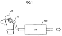
- Figure 1 shows the overall construction of an exhaust gas purifying system of a diesel engine equipped with a diesel particulate filter according to a related art of the present invention.
- a diesel engine 11 has an exhaust line 12, wherein there is provided a diesel particulate filter 12B in the exhaust line 12 for collecting the particulate matter contained in the exhaust gas and emitted from the diesel engine 11.
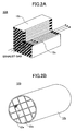
- Figure 2A shows the outline of the diesel particulate filter 12B while Figure 2B shows an element that constitutes the diesel particulate filter.
- the diesel particulate filter 12B is formed of a filter unit 12A of a porous ceramic, typically of SiC, wherein there are formed a large number of gas passages 12a in the filter unit 12A so as to extend from one end to the other end thereof with a cross-section of 1mm ⁇ 1mm, for example.
- the diesel particulate filter 12B is formed by binding plural filter units (filter elements) 12A by a seal material (adhesion layer) and machining the peripheral part thereof such that the filter 12B as a whole has a cylindrical form. Further, the peripheral surface of the filter 12B is covered by a seal material (coating layer). There may be a case in which only one unit 12A is used in the diesel particulate filter 12B.
- Figure 2C shows the principle of the diesel particulate filter 12B.
- the plural gas passages 12a have their upstream ends or downstream ends closed alternately with regard to the direction of the exhaust gas flow from the engine, and the exhaust gas introduced to one such gas passage 12a passes to an adjacent gas passage by way of penetration through the porous member 12b of the filter 12B.
- the particulate matter contained in the exhaust gas is collected by the porous member 12b as the exhaust gas penetrates therethrough, and there is caused deposition of the particulate matter 12c on the porous member 12b in the form of layer as shown in Figure 2D .
- the diesel particulate filter 12B thus causes deposition of the particulate matter contained in the exhaust gas therein, there is a need of regenerating the filter with suitable timing by conducting a regeneration process (burning of the deposited particulate matter), as described previously.
- the regeneration of the diesel particulate filter 12B is carried out only when the differential pressure between the upstream side and the downstream side has reached the predetermined value, and unnecessary post injection process is suppressed. Thereby, the fuel efficiency of the vehicle driven with the diesel engine is improved.
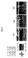
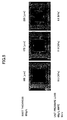
- the density of the collected particulate matter can take different values even when the deposition amount of the particulate matter is identical.
- Figure 5 shows that there is caused a large variation in the differential pressure according to the change of the thickness, even when the deposition amount is identical.
- the deposition amount of the particulate matter is 8g/L throughout.
- the differential pressure has changed from 15.3kPa to 8.8kPa when the thickness of the collected particulate matter has changed from 109 ⁇ m to 255 ⁇ m.
- United States Patent 5,651,248 describes the construction that uses, in addition to the diesel particulate filter, a detection filter and evaluates the amount of the particulate matter collected in the detection filter by measuring the electric resistance.
- the particulate matter collected by the diesel particulate filter and the particulate matter collected by the detection filter are subjected to burning by using a heater when the detected resistance has decreased below a predetermined value. With this, regeneration of filter is achieved.
- this prior art has a drawback in that, in addition to the problem that the construction thereof becomes complex because of the need of providing a heater in the diesel particulate filter, there occurs electric power consumption at the time of regeneration of the diesel particulate filter.
- the technology of United States Patent 5,651,248 selects the timing of executing the filter regeneration such that the regeneration operation is conducted at the time the temperature of the diesel particulate filter is higher than a predetermined temperature, except for the case in which the diesel particulate filter is in the critical state with regard to the deposition of the particulate matter and it is inevitable to carry out regeneration immediately.
- a restriction on the timing of regenerating operation with this technology and the degree of freedom of regenerating operation of the particulate detection filter is restricted.
- regeneration of the detection filter is carried out concurrently with the diesel particulate filter or consecutively to the diesel particulate filter, while such a construction cannot choose the timing of regeneration of the detection filter arbitrarily, and there is a problem that error tends to be caused in the regeneration timing of the diesel particulate filter, depending upon the state of the detection filter.
- the detection filter there is caused degradation in the filter or electrode with time or with use in the ambient of exhaust gas.
- the electrode terminal formed of a conductive metal
- the electrode is formed by infiltrating a metal such as Cu, Cr, Ni, or the like, and thus, there is a tendency of causing problems of physical degradation, oxidation degradation and thermal degradation, such as oxidation, adhesion of impurities, cracking, corrosion, and the like.
- an exhaust gas purifying apparatus comprising:
- the present invention provides an exhaust gas purifying apparatus, comprising:
- the present invention it becomes possible to measure the deposition amount of particulate matter in the primary diesel particulate filter simply and easily, by using the secondary diesel particulate filter of smaller capacity and hence less prone to cause non-uniform deposition of the particulate matter and by detecting the deposition of the particulate matter in the primary diesel particulate filter by measuring the differential pressure occurring in such a secondary diesel particulate filter. Thereby, it becomes possible to suppress deterioration of fuel efficiency by excessive post injection. Further, with the present invention, it becomes possible to execute the regeneration of the secondary diesel particulate filter independently to the primary diesel particulate filter, and it becomes possible to constantly and precisely measure the deposition amount of the particulate matter in the primary diesel particulate filter by using the secondary diesel particulate filter. Further, it becomes possible to perform precise measurement while eliminating the effect of ash deposition or degradation of the filter or electrode.
- the secondary diesel particulate filter within the distance of 2m from the branching point of the secondary exhaust line from the primary exhaust line, or by disposing the secondary diesel particulate filter such that a distance L [m] to said secondary diesel particulate filter from a branching point of said secondary exhaust line from said primary exhaust line satisfies the relationship 50 ⁇ Q ⁇ 5000 (0 ⁇ L ⁇ 1) and 4950L-4900 ⁇ Q ⁇ 5000 (1 ⁇ L ⁇ 2) where Q [ml/min] represents a flow rate of said exhaust gas in said secondary exhaust line represented, it becomes possible to achieve precise evaluation of the deposition amount of the particulate matter even in the case the flow rate of the exhaust gas is small.
- an exhaust gas purifying apparatus including: a primary diesel particulate filter provided in a primary exhaust line of a diesel engine; a secondary exhaust line branched from the primary exhaust line from an upstream side of the primary diesel particulate filter; a secondary diesel particulate filter provided in the secondary exhaust line, the secondary diesel particulate filter having a soot storage capacity smaller than the soot storage capacity of the primary diesel particulate filter; and a differential pressure measuring part measuring a differential pressure between an inlet and an outlet of the secondary diesel particulate filter, wherein a distance to the secondary diesel particulate filter from a branching point of the secondary exhaust line from the primary exhaust line is 2m or less.
- an exhaust gas is caused to flow through the secondary exhaust line with a flow rate of 5000ml/min or less.
- an exhaust gas is caused to flow through said secondary exhaust line with a flow rate of 5000ml/min or less and wherein said distance is 1m or less.
- the secondary exhaust line includes a flow meter or equivalent meter (e.g. a gas velocity meter).
- the secondary diesel particulate filter includes a temperature measuring part.
- secondary diesel particulate filter includes a heater.
- the exhaust gas purifying apparatus further comprises a valve for maintaining a flow rate of an exhaust gas in the secondary exhaust line at a predetermined value.
- the exhaust gas purifying apparatus further comprises a holder, and wherein at least one of the differential pressure measuring part, the temperature measuring part, the secondary diesel particulate filter, and the flow meter or equivalent meter (e.g. a gas velocity meter) is accommodated in the holder.
- the differential pressure measuring part the temperature measuring part, the secondary diesel particulate filter, and the flow meter or equivalent meter (e.g. a gas velocity meter) is accommodated in the holder.
- an exhaust gas purifying apparatus including: a primary diesel particulate filter provided in a primary exhaust line of a diesel engine; a secondary exhaust line branched from the primary exhaust line from an upstream side of the primary diesel particulate filter; a secondary diesel particulate filter provided in the secondary exhaust line, the secondary diesel particulate filter having a soot storage capacity smaller than the soot storage capacity of the primary diesel particulate filter; and a differential pressure measuring part measuring a differential pressure between an inlet and an outlet of the secondary diesel particulate filter, wherein a distance L [m] to the secondary diesel particulate filter from a branching point of said secondary exhaust line from the primary exhaust line is set so as to satisfy the relationship 50 ⁇ Q ⁇ 5000 0 ⁇ L ⁇ 1 4950 ⁇ L - 4900 ⁇ Q ⁇ 5000 1 ⁇ L ⁇ 2 , where Q [ml/min] represents a flow rate of the exhaust gas in the secondary exhaust line.
- the secondary exhaust line includes a flow meter.
- the secondary diesel particulate filter includes a temperature measuring part.
- the secondary diesel particulate filter includes a heater.
- the exhaust gas purifying apparatus further comprises a valve for maintaining a flow rate of an exhaust gas in the secondary exhaust line at a predetermined value.
- the exhaust gas purifying apparatus further includes a holder, and wherein at least one of the differential pressure measuring part, the temperature measuring part, the secondary diesel particulate filter, and the flow meter or equivalent meter (e.g. a gas velocity meter) is accommodated in the holder.
- the differential pressure measuring part the temperature measuring part, the secondary diesel particulate filter, and the flow meter or equivalent meter (e.g. a gas velocity meter) is accommodated in the holder.
- Figure 6 shows the construction of an exhaust gas purifying apparatus 20 according to a first embodiment of the present invention.
- an exhaust gas from a diesel engine not illustrated is caused to flow into a primary diesel particulate filter (DPF) 22 similar to the one explained previously with reference to Figure 2A via an exhaust line 21, and the primary diesel particulate filter (DPF) 22 collects the particulate matter in the exhaust gas as explained with reference to Figures 2C and 2D .
- DPF primary diesel particulate filter
- a secondary exhaust line 21A is branched from the exhaust line 21 from an upstream side of the primary diesel particulate filter (DPF) 22, and a secondary diesel particulate filter 22A is provided to the secondary exhaust line 21A with a volume smaller than the volume of the primary diesel particulate filter (DPF) 22.
- a differential pressure gauge 22B for measuring a differential pressure ⁇ P caused between an inlet and an outlet of the secondary diesel particulate filter 22A.
- the control valve 23 and the flow mater 24 may be provided anywhere on the secondary exhaust line 21A.
- the secondary diesel particulate filter 22A, the differential pressure gauge 22B and the flow meter 24 constitutes together a particulate matter (PM) sensor that measures the amount of particulate contained in the exhaust gas.
- the particulate matter (PM) sensor may be defined to include a temperature measuring part (T1). Further, it is possible to provide a temperature measurement part T2 in the primary diesel particulate filter (DPF) 22.
- T1 temperature measuring part
- T2 temperature measurement part in the primary diesel particulate filter 22.
- the temperature measuring part in the exhaust line may be provided in ay of:
- the primary diesel particulate filter (DPF) 22 is formed of a porous ceramic of SiC, or the like having a porosity of 35 - 65% in the form of a honeycomb structure, wherein it can be seen that there are formed gas passages of a rectangular cross-section having a length of 1.1mm, for example, for each edge in the cross-section taken perpendicular to the gas flow direction, in correspondence to the gas passages 12a of Figure 2B , wherein the gas passages are arranged with a mutual separation of about 0.3mm and form together a lattice pattern.
- Figure 7A shows the overall construction including the secondary diesel particulate filter 22A
- Figure 7B shows the principle of the secondary diesel particulate filter 22A.
- the secondary diesel particulate filter 22A may be formed of a porous ceramic similar to the primary diesel particulate filter (DPF) 22.
- the secondary diesel particulate filter is formed of a porous ceramic, it is preferable that the secondary diesel particulate filter includes a secondary diesel particulate filter 22A (cell 22b) of a rectangular form.
- a single gas passage 22a having a volume of 65ml or less such as 0.05 - 65ml, or 5% or less such as 0.05 - 5% of the total volume of the exhaust gas passages (corresponding to passage 12a of Figure 3 ) in the primary diesel particulate filter (DPF) 22.
- the gas passage 22a may have a filtration area of 0.1 - 1000cm 2 (preferably 1 - 10cm 2 ).
- the gas passage 22a may have a rectangular cross-sectional shape, for example, and is formed in the state that one end thereof is closed (rear end is closed in the case of a cell).
- the outer shape of the gas passage 22a or the outer shape of the secondary diesel particulate filter 22A (cell 22b) is not necessarily be identical to the cross-sectional shape of the gas passages of the primary diesel particulate filter (DPF) 22, and thus, they can be shaped to any arbitrary shape of circular, square, octahedral, elliptical, or the like.
- the porous ceramic constituting the secondary diesel particulate filter 22A is not necessarily be identical with the porous ceramic that forms the primary diesel particular filter (DPF) 22. Further, it should be noted that the secondary diesel particulate filter 22A (cell 22b) may be formed of a material other than ceramics.
- the gas passage 22a With the volume of 5% or less of the exhaust gas passage (corresponds to the passage 12a of Figure 3 ) in the primary diesel particulate filter (DPF) 22, or with the volume of 65ml or less, or with the filtration area of 0.1 - 1000cm 2 (preferably 1 - 10cm 2 ), it becomes possible to measure the deposition amount of the particulate matter in the primary diesel particulate filter (DPF) 22 with a simple procedure.
- the secondary diesel particulate filter 22A (cell 22b) is provided with a temperature measuring part for measuring the exhaust gas temperature T, and a thermocouple 22d is provided for the temperature measuring part. Further, a heater 22h is wound around the secondary diesel particulate filter 22A (cell 22b) for incinerating a soot layer 22c deposited on the inner wall surface and regenerating the secondary diesel particulate filter 22A.
- the secondary diesel particulate filter 22A (cell 22b), the thermocouple 22d and the heater 22h are accommodated in a cylindrical holder 22e of SiO 2 -Al 2 O 3 , or the like, via an insulator 22i of Al 2 O 3 , or the like, and there is provided a diaphragm pressure gauge 22B in the holder 22e for measuring the differential pressure ⁇ P, in such a manner that the exhaust gas in the secondary exhaust line 21A is supplied to the pressure gauge 22B.
- the holder 22e is accommodated in a metal housing and is provided to the secondary exhaust line as the particulate matter (PM) sensor.
- the holder 22e may also be provided inside the pipe of the secondary exhaust line or may be provided inside the secondary exhaust line in the state accommodated in the metal housing.
- the deposition amount of the particulate 22c thus collected and deposited on the inner wall surface of the diesel particulate filter 22 is calculated from the pressure difference ⁇ P and the temperature T and flow rate Q of the exhaust gas thus obtained by using the equation (1) below.
- Figure 8 shows a more detailed construction of the secondary diesel particulate filter 22A of Figure 6 .
- the exhaust gas in the secondary exhaust line 21A is supplied to the gas passage 22a in the secondary diesel particulate filter 22A (cell 22b) as represented by an arrow and is discharged, after passing through the cell, in the lateral direction or rear direction.
- the heater 22h on the secondary diesel particulate filter 22A (cell 22b) is driven by the electric power supplied by a drive line 22b1 and causes incineration in the particulate matter 22c collected by the secondary diesel particulate filter 22A (cell 22b).
- the output signal of the diaphragm pressure gauge 22B is supplied to a control circuit via a signal line 22p.
- a collection amount per unit time, PM [g/h] is obtained by dividing m soot by the time [h] as measured from the previous regeneration of the secondary diesel particulate filter 22A.
- Q1 represents the flow rate of the exhaust gas passing through the primary diesel particulate filter (DPF) 22.
- Q1 may be obtained by actual measurement or estimated from the operational state of the engine.
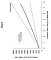
- Figure 9 shows the relationship between the differential pressure occurring across the primary diesel particulate filter (DPF) 22 of the exhaust gas purifying apparatus of Figure 6 and the deposition amount of the particulate matter in the primary diesel particulate filter (DPF) 22, wherein it should be noted that the continuous line shows the case in which the deposition amount of the particulate matter in the main diesel particulate filter 22 is obtained by using the secondary diesel particulate filter 22A and Equations (1) - (4). On the other hand, the dotted line represents the case in which the deposition amount of the particulate matter in the primary diesel particulate filter (DPF) 22 is obtained directly from the differential pressure across the primary diesel particulate filter (DPF) 22.
- the present invention it becomes possible to evaluate the deposition amount of the particulate matter in the primary diesel particulate filter (DPF) 22 in the exhaust gas purifying apparatus of Figure 6 precisely by measuring the differential pressure ⁇ P formed in the secondary diesel particulate filter 22A of small volume, and it becomes possible to execute the regeneration of the primary diesel particulate filter (DPF) 22 with optimum timing by way of carrying out the post injection based on the foregoing result. With this, unnecessary post injection is avoided and the fuel efficiency of the vehicle is improved.
- the "differential pressure measuring part measuring a differential pressure between an inlet and an outlet of said secondary diesel particulate filter” includes not only the differential pressure gauge that measures the differential pressure between the inlet side and the outlet side of the secondary diesel particulate filter 22A but also the construction that uses a pressure gauge only at the outlet side of the diesel particulate filter 22A.
- the pressure value of the initial state (the state immediately after regeneration) is memorized and the differential pressure is calculated by measuring the pressure for the state in which there occurred deposition of the particulate material in the secondary diesel particulate filter 22A and by subtracting the pressure value thus obtained from the memorized initial pressure value.
- the differential pressure is obtained from the reading value of the flow meters or flow velocity meters provided at the inlet side and the outlet side of the secondary diesel particulate filter.
- the differential pressure may be obtained from the reading value of the flow meter, the flow velocity meter or the like at the outlet side of the secondary diesel particulate filter, by comparing the reading value for the initial state (the state immediately after regeneration) and the reading value for the state where there is caused deposition of the particulate matter in the secondary diesel particulate filter.
- the present invention has the feature of obtaining the amount of the particulate matter deposited in the primary diesel particulate filter (DPF) 22 from the differential pressure obtained for the secondary diesel particulate filter 22A by using Equation (1), and thus, any instruments including those that are used conventionally for measuring a differential pressure may be used for measuring the differential pressure of the secondary diesel particulate filter.
- DPF primary diesel particulate filter
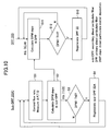
- Figure 10 is a flowchart showing the exhaust gas purifying method according to a second embodiment of the present invention that uses the exhaust gas purifying apparatus of Figure 6 .
- the flow rate in the secondary exhaust line 21A is set to a predetermined value in the range of 50 - 6000ml/min in the step 1 by using the flow meter 24, or in some cases by using the valve 23, and the differential pressure ⁇ P across the secondary diesel particulate filter 22A is detected by the differential pressure gauge 22B. Further, the temperature of the exhaust gas is detected by using the temperature measuring part T1.
- the layer thickness W of the particulate matter collected by the secondary diesel particulate filter 22A is obtained from the differential pressure ⁇ P detected in the step 1 according to Equation (1).
- the temperature T of the exhaust gas may be obtained by using the temperature measuring part T2 of the primary diesel particulate filter (DPF) 22 in place of using the temperature measuring part T1 of the secondary diesel particulate filter 22A.
- the temperature T may be calculated from the temperatures of the temperature measuring parts T1 and T2 (in the form of average value, maximum value, minimum value, for example). From the viewpoint of calculating the amount of the particulate matter more precisely, it is preferable to use the temperature measuring part T1 of the secondary diesel particulate filter 22A.
- thermometer a thermocouple may be used, while it is also possible to use anything as long as it can measure the temperature. While it is preferable to measure the temperature of the exhaust gas inside the exhaust pipe, it is also possible to measure the temperature of the filter or the cell.
- the mass m soot of the particulate matter collected by the cell 21b is obtained from the layer thickness W detected in the step 1 by using Equation (2) mentioned previously.
- step 3 it is judged whether or not the mass m soot of the layered particulate matter deposited in the secondary diesel particulate filter 22A (cell 22b) of the secondary diesel particulate filter 22A has exceeded a predetermined threshold Th0, and if the result is NO, the process returns to the step 1.
- the concentration PM of the particulate matter in the exhaust gas is obtained in the step 11 from Equation (3) while using the mass m soot of the collected particulate matter in the secondary diesel particulate filter 22A (cell 22b) obtained in the step 2, and the deposited amount PM enter full filter of the particulate deposited in the principal diesel particulate filter 22 is obtained from Equation (4) and from the collection efficiency of the primary diesel particulate filter (DPF) 22.
- step 12 it is judged whether or not the deposited amount PM enter full filter of the particulate matter in the primary diesel particulate filter (DPF) 22 exceeds a predetermined threshold value Th1, and if the result of judgment is NO, the operation returns to the step S11.
- post injection is executed in the step 13 by controlling an engine control unit (ECU), and the deposited particulate matter in the primary diesel particulate filter (DPF) 22 is removed by burning. Thereby, regeneration of filter is achieved.
- ECU engine control unit
- valve 23 there is no need for the valve 23 to maintain the exhaust gas flow rate in the secondary exhaust line 21A exactly at a constant level but it is just sufficient to avoid extreme deviation of the exhaust gas flow to the secondary exhaust line 21A.
- the differential pressure ⁇ P, the exhaust gas temperature T and the exhaust gas flow rate Q are measured (step 1), the mass of the particulate matter collected by the secondary diesel particulate filter is obtained by using Equations (1) and (2) from the foregoing result of measurement (step 2), and the amount of the particulate matter collected by the primary diesel particulate filter is obtained from the amount of the particulate matter collected in the secondary diesel particulate filter by using Equations (3) and (4) and further using the collection efficiency of the primary diesel particulate filter (step 11).
- the primary diesel particulate filter (DPF) 22 is designated as DPF while the secondary diesel particulate filter 22A is designated as sub-DPF. Further, the deposition of diesel particulate matter is designated as DPM depo.
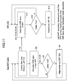
- the process of obtaining the amount of the particulate matter collected in the primary diesel particulate filter may be modified as shown in Figure 11 .
- step 11 the process for obtaining the amount of the particulate matter collected by the primary diesel particulate filter (step 11) is carried out in parallel with the process of obtaining the amount of the particulate matter collected by the secondary diesel particulate filter (step 2), while using the result of measurement obtained in the step 1.
- Figure 12 is a graph showing the area in which the mass of the particulate matter deposited in the primary diesel particulate filter (DPF) 22 can be evaluated accurately within the error of ⁇ 10% wherein Figure 12 represents the area as a function of the flow rate Q [ml/min] of the exhaust gas flowing through the secondary exhaust line 21A and a distance L, wherein the distance L is defined in Figure 6 and represents the distance to the secondary diesel particulate filter 22A from the point in which the secondary exhaust line 21A has branched from the primary exhaust line 21.
- the experiment of Figure 12 was conducted by providing the exhaust gas purifying apparatus of Figure 6 to the exhaust line of a two-litter diesel engine and operating the diesel engine at the condition of 3000rpm/50N for 5 hours.
- the deposition amount of the particulate matter in the primary diesel particulate filter (DPF) 22 is obtained.
- the exhaust gas was emitted to the exhaust line 21 with a flow rate of about 35Om 3 /h.
- the error between the amount of the particulate matter actually deposited on the primary diesel particulate filter (DPF) 22 and the amount of the particulate matter in the primary diesel particulate filter (DPF) 22 as evaluated from the differential pressure of the secondary diesel particulate filter 22A was obtained while changing the distance to the secondary diesel particulate filter from the branching point of the secondary exhaust line 21A from the exhaust line 21 variously.
- the amount of the particulate matter actually deposited in the primary diesel particulate filter (DPF) 22 is obtained directly by measuring the weight of the filter 22.
- the diameter of the exhaust line 21 is set to 10mm, while the diameter of the secondary exhaust line 21A is set to 150mm. Further, the flow rate of the exhaust gas in the secondary exhaust line 21A is changed in the range of 0 - 5000ml/min. Further, the regeneration of the secondary particulate filter 22A is carried out each time the particulate matter is deposited to the filter 22A with the amount of 0.5g/l.
- Figure 12 is a graph showing the result of Table 2 above, wherein ⁇ represents the data point where the error is 10% or less, while ⁇ represents the data point where the error exceeds 10%. Further, the broken line represents the boundary between the data points ⁇ and the data points ⁇ .
- the foregoing results indicate that it is preferable to design the exhaust gas purifying apparatus of Figure 6 such that the foregoing relationship is satisfied and the operational point falls within the region defined in Figure 12 by the broken lines.
- the distance L is set preferably to 2m or less. When the distance L exceeds 2m, it is no longer possible to evaluate the deposition amount of the particulate matter in the primary diesel particulate filter (DPF) 22 within the error of 10%, even when the flow rate of the exhaust gas is increased.
- DPF primary diesel particulate filter
- the present invention is by no means limited to such particular filter components, and it is also possible to use Si-SiC, a nitride such as aluminum nitride, silicon nitride, boron nitride, tungsten nitride, or the like, a carbide such as Zirconium carbide, titanium carbide, tantalum carbide, tungsten carbide, or the like, an oxide such as alumina, zirconium oxide, cordierite, mullite, silica, aluminum titanate, or a porous body of metal such as stainless steel. Further, it is possible to use a structural body such as corrugate or element plate in addition to the honeycomb structure.
- a structural body such as corrugate or element plate in addition to the honeycomb structure.
- the exhaust gas purifying apparatus of the present invention has a compact size and is applicable not only to large vehicles such as trucks or industrial machines but also to passenger cars.
Landscapes
- Engineering & Computer Science (AREA)
- Chemical & Material Sciences (AREA)
- Combustion & Propulsion (AREA)
- Mechanical Engineering (AREA)
- General Engineering & Computer Science (AREA)
- Analytical Chemistry (AREA)
- Life Sciences & Earth Sciences (AREA)
- General Physics & Mathematics (AREA)
- Physics & Mathematics (AREA)
- Health & Medical Sciences (AREA)
- Chemical Kinetics & Catalysis (AREA)
- Biochemistry (AREA)
- General Health & Medical Sciences (AREA)
- Dispersion Chemistry (AREA)
- Immunology (AREA)
- Pathology (AREA)
- Processes For Solid Components From Exhaust (AREA)
- Filtering Of Dispersed Particles In Gases (AREA)
- Treating Waste Gases (AREA)
- Incineration Of Waste (AREA)
- Electrical Discharge Machining, Electrochemical Machining, And Combined Machining (AREA)
Priority Applications (7)
| Application Number | Priority Date | Filing Date | Title |
|---|---|---|---|
| AT06386031T ATE460571T1 (de) | 2006-10-17 | 2006-10-17 | Abgasreinigungsvorrichtung |
| EP06386031A EP1914399B8 (de) | 2006-10-17 | 2006-10-17 | Abgasreinigungsvorrichtung |
| DE602006012846T DE602006012846D1 (de) | 2006-10-17 | 2006-10-17 | Abgasreinigungsvorrichtung |
| JP2007209680A JP4951441B2 (ja) | 2006-10-17 | 2007-08-10 | 排ガス浄化装置 |
| US11/852,141 US7891176B2 (en) | 2006-10-17 | 2007-09-07 | Exhaust gas purifying apparatus |
| CNB2007101616627A CN100549375C (zh) | 2006-10-17 | 2007-09-27 | 排气净化装置 |
| KR1020070097758A KR100899966B1 (ko) | 2006-10-17 | 2007-09-28 | 배기가스 정화 장치 |
Applications Claiming Priority (1)
| Application Number | Priority Date | Filing Date | Title |
|---|---|---|---|
| EP06386031A EP1914399B8 (de) | 2006-10-17 | 2006-10-17 | Abgasreinigungsvorrichtung |
Publications (3)
| Publication Number | Publication Date |
|---|---|
| EP1914399A1 true EP1914399A1 (de) | 2008-04-23 |
| EP1914399B1 EP1914399B1 (de) | 2010-03-10 |
| EP1914399B8 EP1914399B8 (de) | 2010-05-12 |
Family
ID=37985222
Family Applications (1)
| Application Number | Title | Priority Date | Filing Date |
|---|---|---|---|
| EP06386031A Not-in-force EP1914399B8 (de) | 2006-10-17 | 2006-10-17 | Abgasreinigungsvorrichtung |
Country Status (7)
| Country | Link |
|---|---|
| US (1) | US7891176B2 (de) |
| EP (1) | EP1914399B8 (de) |
| JP (1) | JP4951441B2 (de) |
| KR (1) | KR100899966B1 (de) |
| CN (1) | CN100549375C (de) |
| AT (1) | ATE460571T1 (de) |
| DE (1) | DE602006012846D1 (de) |
Cited By (3)
| Publication number | Priority date | Publication date | Assignee | Title |
|---|---|---|---|---|
| EP2236786A1 (de) * | 2009-03-31 | 2010-10-06 | Ibiden Co., Ltd. | Vorrichtung zur Konzentrationsmessung von Partikeln |
| EP2366877A1 (de) * | 2010-03-16 | 2011-09-21 | Ibiden Co., Ltd. | Sensor für eine Abgasreinigungsvorrichtung |
| EP3048278A1 (de) * | 2015-01-26 | 2016-07-27 | Bosal Emission Control Systems NV | Vorrichtung zur Diagnose der Funktionsfähigkeit eines Teilchenfilters für einen Abgasstrom einer Brennkraftmaschine |
Families Citing this family (26)
| Publication number | Priority date | Publication date | Assignee | Title |
|---|---|---|---|---|
| EP1914536A1 (de) * | 2006-10-17 | 2008-04-23 | Ibiden Co., Ltd. | Sensor für Partikel-Material |
| US7658064B2 (en) * | 2006-10-17 | 2010-02-09 | Ibiden Co., Ltd. | Exhaust gas purifying apparatus |
| PL1916394T3 (pl) * | 2006-10-17 | 2009-08-31 | Ibiden Co Ltd | Urządzenie oczyszczające gazy wydechowe, sposób oczyszczania gazów wydechowych oraz sposób pomiaru osadu cząstek stałych |
| EP1914537A1 (de) * | 2006-10-17 | 2008-04-23 | Ibiden Co., Ltd. | Sensor für Partikel-Material |
| DE102007013500A1 (de) * | 2007-03-21 | 2008-09-25 | Bayerische Motoren Werke Aktiengesellschaft | Abgasstrang für einen Verbrennungsmotor |
| US8646257B2 (en) | 2008-09-10 | 2014-02-11 | Mack Trucks, Inc. | Method for estimating soot loading in a diesel particulate filter, and engine and aftertreatment system |
| JP2012062755A (ja) * | 2009-03-31 | 2012-03-29 | Ibiden Co Ltd | 微粒子濃度測定装置 |
| WO2010113294A1 (ja) * | 2009-03-31 | 2010-10-07 | イビデン株式会社 | 微粒子濃度測定装置 |
| WO2010113295A1 (ja) * | 2009-03-31 | 2010-10-07 | イビデン株式会社 | 微粒子濃度測定装置 |
| WO2010113292A1 (ja) * | 2009-03-31 | 2010-10-07 | イビデン株式会社 | 微粒子濃度測定装置 |
| WO2011032933A1 (fr) * | 2009-09-15 | 2011-03-24 | Zidat Said | Dispositif de diagnostic d'un filtre a particules |
| KR20100126163A (ko) * | 2009-12-04 | 2010-12-01 | 주식회사 알란텀 | 배기가스 여과 장치 |
| US8534055B2 (en) * | 2010-03-29 | 2013-09-17 | Thermo King Corporation | Filter arrangement for exhaust aftertreatment system |
| US8447461B2 (en) * | 2010-10-01 | 2013-05-21 | Deere & Company | Particulate filter ash loading prediction method and vehicle with same |
| DE102010038153B3 (de) * | 2010-10-13 | 2012-03-08 | Ford Global Technologies, Llc. | Partikelsensor, Abgassystem und Verfahren zum Schutz von Komponenten eines turbogeladenen Motors mit Abgasrückführung |
| WO2012078660A1 (en) * | 2010-12-06 | 2012-06-14 | Greene Environmental Corporation | Systems and methods for improving fuel efficiency |
| JP5325249B2 (ja) * | 2011-03-18 | 2013-10-23 | 株式会社小松製作所 | 粒子状物質堆積量推定装置、排気ガス浄化システム、および粒子状物質堆積量推定方法 |
| AT509667B1 (de) * | 2011-07-18 | 2013-02-15 | Avl List Gmbh | Verfahren zur ermittlung der partikelanzahl im abgas von verbrennungsmotoren |
| CN103946507B (zh) * | 2011-10-26 | 2017-07-21 | 博夏特汽车测试服务有限公司 | 用于柴油微粒过滤器的过热/过压安全装置 |
| JP6379838B2 (ja) * | 2014-08-11 | 2018-08-29 | いすゞ自動車株式会社 | センサ |
| US10281384B2 (en) * | 2015-08-25 | 2019-05-07 | Ford Global Technologies, Llc | Method and system for exhaust particulate matter sensing |
| US9551259B1 (en) * | 2015-08-26 | 2017-01-24 | Ford Global Technologies, Llc | Method and system for diesel particulate filter diagnostics |
| US9551262B1 (en) * | 2015-10-13 | 2017-01-24 | Ford Global Technologies, Llc | Method and system for particulate filter leakage detection |
| RU2017125943A (ru) * | 2016-07-29 | 2019-01-21 | Форд Глобал Текнолоджиз, Ллк | Способ и система для обнаружения твердых частиц в отработавшихся газах |
| KR102371238B1 (ko) * | 2017-04-03 | 2022-03-04 | 현대자동차 주식회사 | 차량의 배기가스 정화장치 및 재생방법 |
| JP7087722B2 (ja) * | 2018-06-26 | 2022-06-21 | マツダ株式会社 | エンジンの排気装置 |
Citations (3)
| Publication number | Priority date | Publication date | Assignee | Title |
|---|---|---|---|---|
| US5651248A (en) * | 1994-08-29 | 1997-07-29 | Isuzu Ceramics Research Institute Co., Ltd. | Diesel particulate filter apparatus |
| US5651250A (en) * | 1994-05-24 | 1997-07-29 | Isuzu Ceramics Research Institute Co., Ltd. | Diesel particulate filter apparatus |
| US20010013220A1 (en) * | 1999-12-10 | 2001-08-16 | Heraeus Electro-Nite International N.V. | Measuring arrangement and method for monitoring the operability of a soot filter |
Family Cites Families (26)
| Publication number | Priority date | Publication date | Assignee | Title |
|---|---|---|---|---|
| JPS56118641A (en) * | 1980-02-22 | 1981-09-17 | Nippon Soken Inc | Fine particle discharge amount measuring apparatus for vehicle |
| JP2894103B2 (ja) * | 1992-09-09 | 1999-05-24 | 松下電器産業株式会社 | 排気ガス浄化装置 |
| JP3054514B2 (ja) * | 1993-06-17 | 2000-06-19 | 株式会社ファームテック | 排気ガスの混合物質捕集方法 |
| US5582002A (en) * | 1994-06-29 | 1996-12-10 | Pattas; Konstantin | Method of and an apparatus for controlled regeneration of a diesel soot filter |
| JPH08232643A (ja) * | 1995-02-28 | 1996-09-10 | Matsushita Electric Ind Co Ltd | 排ガス浄化方法及び排ガス浄化装置 |
| JP2000028499A (ja) * | 1998-07-15 | 2000-01-28 | Farm Tec:Kk | 排気ガス中の混合物質捕集装置 |
| JP2000292322A (ja) * | 1999-04-02 | 2000-10-20 | Ono Sokki Co Ltd | 抽出希釈装置及びサンプル採取装置 |
| JP2001188031A (ja) * | 1999-10-18 | 2001-07-10 | Firmware Technology Co Ltd | 排気ガス中の粒子状物質の測定方法および測定装置 |
| JP3546949B2 (ja) | 2000-04-28 | 2004-07-28 | トヨタ自動車株式会社 | 内燃機関の排気浄化装置 |
| US7021048B2 (en) * | 2002-01-25 | 2006-04-04 | Arvin Technologies, Inc. | Combination emission abatement assembly and method of operating the same |
| JP2006097469A (ja) * | 2002-10-01 | 2006-04-13 | Tokudaiji Jidosha Bunka Kenkyusho:Kk | ディーゼルエンジン低負荷時におけるpm連続再生方法 |
| JP3951899B2 (ja) * | 2002-11-15 | 2007-08-01 | いすゞ自動車株式会社 | ディーゼルエンジンの排気浄化装置 |
| JP4089396B2 (ja) * | 2002-11-15 | 2008-05-28 | いすゞ自動車株式会社 | ターボチャージャーを備えた内燃機関のegrシステム |
| US6779339B1 (en) * | 2003-05-02 | 2004-08-24 | The United States Of America As Represented By The Environmental Protection Agency | Method for NOx adsorber desulfation in a multi-path exhaust system |
| EP1477801B1 (de) * | 2003-05-14 | 2005-09-14 | Pierburg Instruments GmbH | Verfahren und Vorrichtung zur Abgasmessung von Verbrennungskraftmaschinen |
| JP3896998B2 (ja) | 2003-07-08 | 2007-03-22 | トヨタ自動車株式会社 | 内燃機関の排気浄化装置 |
| JP4103719B2 (ja) | 2003-07-31 | 2008-06-18 | 日産自動車株式会社 | エンジンの排気浄化装置および微粒子捕集フィルタの微粒子堆積状態判定方法 |
| JP2005127735A (ja) * | 2003-10-21 | 2005-05-19 | Hino Motors Ltd | 部分希釈トンネル装置 |
| JP2005240652A (ja) | 2004-02-25 | 2005-09-08 | Ishino Consulting Capital:Kk | 安全機能付dpf装置 |
| JP2006118357A (ja) | 2004-10-19 | 2006-05-11 | Nissan Motor Co Ltd | 排気ガス浄化装置 |
| JP4553363B2 (ja) * | 2005-02-17 | 2010-09-29 | ボッシュ株式会社 | パティキュレート量の測定装置、パティキュレート量の測定方法、及び排気浄化装置 |
| US7484357B2 (en) * | 2005-09-15 | 2009-02-03 | Cummins, Inc | Apparatus, system, and method for determining and implementing estimate reliability |
| PL1916394T3 (pl) * | 2006-10-17 | 2009-08-31 | Ibiden Co Ltd | Urządzenie oczyszczające gazy wydechowe, sposób oczyszczania gazów wydechowych oraz sposób pomiaru osadu cząstek stałych |
| EP1914536A1 (de) * | 2006-10-17 | 2008-04-23 | Ibiden Co., Ltd. | Sensor für Partikel-Material |
| US7658064B2 (en) * | 2006-10-17 | 2010-02-09 | Ibiden Co., Ltd. | Exhaust gas purifying apparatus |
| EP1914537A1 (de) * | 2006-10-17 | 2008-04-23 | Ibiden Co., Ltd. | Sensor für Partikel-Material |
-
2006
- 2006-10-17 AT AT06386031T patent/ATE460571T1/de not_active IP Right Cessation
- 2006-10-17 EP EP06386031A patent/EP1914399B8/de not_active Not-in-force
- 2006-10-17 DE DE602006012846T patent/DE602006012846D1/de active Active
-
2007
- 2007-08-10 JP JP2007209680A patent/JP4951441B2/ja not_active Expired - Fee Related
- 2007-09-07 US US11/852,141 patent/US7891176B2/en not_active Expired - Fee Related
- 2007-09-27 CN CNB2007101616627A patent/CN100549375C/zh not_active Expired - Fee Related
- 2007-09-28 KR KR1020070097758A patent/KR100899966B1/ko not_active Expired - Fee Related
Patent Citations (3)
| Publication number | Priority date | Publication date | Assignee | Title |
|---|---|---|---|---|
| US5651250A (en) * | 1994-05-24 | 1997-07-29 | Isuzu Ceramics Research Institute Co., Ltd. | Diesel particulate filter apparatus |
| US5651248A (en) * | 1994-08-29 | 1997-07-29 | Isuzu Ceramics Research Institute Co., Ltd. | Diesel particulate filter apparatus |
| US20010013220A1 (en) * | 1999-12-10 | 2001-08-16 | Heraeus Electro-Nite International N.V. | Measuring arrangement and method for monitoring the operability of a soot filter |
Cited By (3)
| Publication number | Priority date | Publication date | Assignee | Title |
|---|---|---|---|---|
| EP2236786A1 (de) * | 2009-03-31 | 2010-10-06 | Ibiden Co., Ltd. | Vorrichtung zur Konzentrationsmessung von Partikeln |
| EP2366877A1 (de) * | 2010-03-16 | 2011-09-21 | Ibiden Co., Ltd. | Sensor für eine Abgasreinigungsvorrichtung |
| EP3048278A1 (de) * | 2015-01-26 | 2016-07-27 | Bosal Emission Control Systems NV | Vorrichtung zur Diagnose der Funktionsfähigkeit eines Teilchenfilters für einen Abgasstrom einer Brennkraftmaschine |
Also Published As
| Publication number | Publication date |
|---|---|
| CN100549375C (zh) | 2009-10-14 |
| US20080087012A1 (en) | 2008-04-17 |
| JP4951441B2 (ja) | 2012-06-13 |
| JP2008101603A (ja) | 2008-05-01 |
| CN101165323A (zh) | 2008-04-23 |
| KR20080034769A (ko) | 2008-04-22 |
| EP1914399B8 (de) | 2010-05-12 |
| DE602006012846D1 (de) | 2010-04-22 |
| US7891176B2 (en) | 2011-02-22 |
| KR100899966B1 (ko) | 2009-05-28 |
| EP1914399B1 (de) | 2010-03-10 |
| ATE460571T1 (de) | 2010-03-15 |
Similar Documents
| Publication | Publication Date | Title |
|---|---|---|
| EP1914399B1 (de) | Abgasreinigungsvorrichtung | |
| US7866146B2 (en) | Exhaust gas purifying apparatus, exhaust gas purifying method, and particulate matter measuring method | |
| EP1921289B1 (de) | Abgasreinigungsvorrichtung | |
| US8127592B2 (en) | Particulate matter detection sensor | |
| US7658064B2 (en) | Exhaust gas purifying apparatus | |
| US20080087101A1 (en) | Particulate matter sensor | |
| JP4042476B2 (ja) | 内燃機関の排気ガス浄化装置 | |
| EP2236786B1 (de) | Vorrichtung zur Konzentrationsmessung von Partikeln | |
| EP2237016A2 (de) | Vorrichtung zur Konzentrationsmessung von Schwebstoffen | |
| CN101782011A (zh) | 用于排气颗粒过滤器的车载性能监测的设备和方法 | |
| US8092565B2 (en) | Particulate filter | |
| JP2012184768A (ja) | 排ガス浄化装置 | |
| JP2014101802A (ja) | 触媒の劣化判定方法と排ガス浄化システム |
Legal Events
| Date | Code | Title | Description |
|---|---|---|---|
| PUAI | Public reference made under article 153(3) epc to a published international application that has entered the european phase |
Free format text: ORIGINAL CODE: 0009012 |
|
| 17P | Request for examination filed |
Effective date: 20071114 |
|
| AK | Designated contracting states |
Kind code of ref document: A1 Designated state(s): AT BE BG CH CY CZ DE DK EE ES FI FR GB GR HU IE IS IT LI LT LU LV MC NL PL PT RO SE SI SK TR |
|
| AX | Request for extension of the european patent |
Extension state: AL BA HR MK RS |
|
| 17Q | First examination report despatched |
Effective date: 20080424 |
|
| AKX | Designation fees paid |
Designated state(s): AT BE BG CH CY CZ DE DK EE ES FI FR GB GR HU IE IS IT LI LT LU LV MC NL PL PT RO SE SI SK TR |
|
| GRAP | Despatch of communication of intention to grant a patent |
Free format text: ORIGINAL CODE: EPIDOSNIGR1 |
|
| GRAS | Grant fee paid |
Free format text: ORIGINAL CODE: EPIDOSNIGR3 |
|
| GRAA | (expected) grant |
Free format text: ORIGINAL CODE: 0009210 |
|
| AK | Designated contracting states |
Kind code of ref document: B1 Designated state(s): AT BE BG CH CY CZ DE DK EE ES FI FR GB GR HU IE IS IT LI LT LU LV MC NL PL PT RO SE SI SK TR |
|
| REG | Reference to a national code |
Ref country code: GB Ref legal event code: FG4D |
|
| REG | Reference to a national code |
Ref country code: CH Ref legal event code: PK Free format text: DIE BENNENNUNG CH/LI WURDE VOR DER ERTEILUNG ZURUECKGENOMMEN. Ref country code: CH Ref legal event code: EP |
|
| RBV | Designated contracting states (corrected) |
Designated state(s): DE FI FR |
|
| REG | Reference to a national code |
Ref country code: NL Ref legal event code: XEP Effective date: 20100226 |
|
| REG | Reference to a national code |
Ref country code: IE Ref legal event code: FG4D |
|
| REF | Corresponds to: |
Ref document number: 602006012846 Country of ref document: DE Date of ref document: 20100422 Kind code of ref document: P |
|
| PLBE | No opposition filed within time limit |
Free format text: ORIGINAL CODE: 0009261 |
|
| STAA | Information on the status of an ep patent application or granted ep patent |
Free format text: STATUS: NO OPPOSITION FILED WITHIN TIME LIMIT |
|
| 26N | No opposition filed |
Effective date: 20101213 |
|
| REG | Reference to a national code |
Ref country code: FR Ref legal event code: PLFP Year of fee payment: 11 |
|
| PGFP | Annual fee paid to national office [announced via postgrant information from national office to epo] |
Ref country code: FR Payment date: 20160919 Year of fee payment: 11 |
|
| PGFP | Annual fee paid to national office [announced via postgrant information from national office to epo] |
Ref country code: FI Payment date: 20161010 Year of fee payment: 11 |
|
| REG | Reference to a national code |
Ref country code: FR Ref legal event code: ST Effective date: 20180629 |
|
| PG25 | Lapsed in a contracting state [announced via postgrant information from national office to epo] |
Ref country code: FI Free format text: LAPSE BECAUSE OF NON-PAYMENT OF DUE FEES Effective date: 20171017 |
|
| PG25 | Lapsed in a contracting state [announced via postgrant information from national office to epo] |
Ref country code: FR Free format text: LAPSE BECAUSE OF NON-PAYMENT OF DUE FEES Effective date: 20171031 |
|
| PGFP | Annual fee paid to national office [announced via postgrant information from national office to epo] |
Ref country code: DE Payment date: 20240828 Year of fee payment: 19 |
|
| REG | Reference to a national code |
Ref country code: DE Ref legal event code: R119 Ref document number: 602006012846 Country of ref document: DE |
|
| PG25 | Lapsed in a contracting state [announced via postgrant information from national office to epo] |
Ref country code: DE Free format text: LAPSE BECAUSE OF NON-PAYMENT OF DUE FEES Effective date: 20260501 |