EP1914429A2 - Motorenkühlung für Gasverdichtungsanlagen - Google Patents
Motorenkühlung für Gasverdichtungsanlagen Download PDFInfo
- Publication number
- EP1914429A2 EP1914429A2 EP07254050A EP07254050A EP1914429A2 EP 1914429 A2 EP1914429 A2 EP 1914429A2 EP 07254050 A EP07254050 A EP 07254050A EP 07254050 A EP07254050 A EP 07254050A EP 1914429 A2 EP1914429 A2 EP 1914429A2
- Authority
- EP
- European Patent Office
- Prior art keywords
- gas
- compressor
- electric motor
- cooling
- treatment device
- Prior art date
- Legal status (The legal status is an assumption and is not a legal conclusion. Google has not performed a legal analysis and makes no representation as to the accuracy of the status listed.)
- Withdrawn
Links
Images
Classifications
-
- F—MECHANICAL ENGINEERING; LIGHTING; HEATING; WEAPONS; BLASTING
- F04—POSITIVE - DISPLACEMENT MACHINES FOR LIQUIDS; PUMPS FOR LIQUIDS OR ELASTIC FLUIDS
- F04D—NON-POSITIVE-DISPLACEMENT PUMPS
- F04D29/00—Details, component parts, or accessories
- F04D29/58—Cooling; Heating; Diminishing heat transfer
- F04D29/582—Cooling; Heating; Diminishing heat transfer specially adapted for elastic fluid pumps
- F04D29/5826—Cooling at least part of the working fluid in a heat exchanger
-
- F—MECHANICAL ENGINEERING; LIGHTING; HEATING; WEAPONS; BLASTING
- F04—POSITIVE - DISPLACEMENT MACHINES FOR LIQUIDS; PUMPS FOR LIQUIDS OR ELASTIC FLUIDS
- F04D—NON-POSITIVE-DISPLACEMENT PUMPS
- F04D25/00—Pumping installations or systems
- F04D25/02—Units comprising pumps and their driving means
- F04D25/06—Units comprising pumps and their driving means the pump being electrically driven
-
- F—MECHANICAL ENGINEERING; LIGHTING; HEATING; WEAPONS; BLASTING
- F04—POSITIVE - DISPLACEMENT MACHINES FOR LIQUIDS; PUMPS FOR LIQUIDS OR ELASTIC FLUIDS
- F04D—NON-POSITIVE-DISPLACEMENT PUMPS
- F04D29/00—Details, component parts, or accessories
- F04D29/58—Cooling; Heating; Diminishing heat transfer
- F04D29/5806—Cooling the drive system
Definitions
- the present application relates generally to systems for cooling motors used in gas compression applications. More specifically, the present application relates to integrated systems for cooling electric motors used in gas compression applications with gas.
- Gas compression is required in the chemical, oil and gas industry for pumping natural gas from on-shore or off-shore wells to processing plants, for gas transmission, for collecting gas in storage facilities for use in peak hours, and other similar applications. Gas compression also is needed for downstream applications in the hydrocarbon processing and chemical industries, as well as for gas distribution to end-users.
- the natural gas compressors used in these applications generally are driven by gas turbines, low-speed synchronous motors with a gearbox, or high-speed directly coupled induction or synchronous motors.
- electrically driven motors have certain advantages over mechanically driven motors such as gas turbines. These advantages including greater operational flexibility, i.e., the ability to operate more efficiently at variable speeds, maintainability, reliability, lower capital investment and operational cost, better efficiency, and being more environmentally friendly.
- high-speed electric drive motors have certain advantages over low speed electric drive motors with a gearbox. These advantages include a smaller footprint, greater simplicity, with the elimination of the gearbox, more efficient integration of cooling systems with the compressor, and higher reliability. A smaller footprint and greater simplicity may be achieved by integration of the motor and compressor casing, which provides the additional advantage of eliminating external gas seals.
- the high-speed motor may be connected directly to the compressor.
- the motor generally is ventilated via a cooling circuit that uses high-pressure gas from the compressor.
- the sealing system between the motor and the compressor is required to handle only the pressure difference between the two components.
- Such a system also is an internal seal. As such, any leakage is contained within the motor-compressor casing system and not released to the environment.
- the present application thus describes a gas compression system that may include an electric motor that drives a compressor, a gas treatment device, and a gas cooling device.
- the electric motor may be cooled by a circulating flow of gas that is cooled by the gas cooling device and had been treated by the gas treatment device.
- the gas compression system may further include a gas feed that provides a supply of raw gas and a valve connected to the gas feed that controls a flow of raw gas from the gas feed to the gas treatment device.
- the valve may control the flow of raw gas from the gas feed to the gas treatment device such that any of the circulating flow of gas that is lost due to leakage is replaced.
- the gas treatment device may remove corrosive impurities or abrasive from the supply of raw gas.
- the gas compression system may further include a cooling gas compressor that is driven by the electric motor.
- the cooling gas compressor may compress the circulating flow of gas before the circulating flow of gas passes through the electric motor.
- the electric motor and the compressor may be located within a motor-compressor casing.
- the electric motor and the cooling gas compressor may be located within an internal casing, which is located within the motor-compressor casing.
- the internal casing may be sealed within the motor-compressor casing by a plurality of internal seals. The internal seals may withstand the pressure differential between the pressure maintained within the internal casing and pressure maintained between the internal casing and the compressor-motor casing.
- any of the circulating flow of gas that leaks from the internal casing may be directed by a maintained pressure differential to the compressor for compression.
- the electric motor may be a high-speed electric motor.
- a drive train of the compressor, the electric motor, and cooling gas compressor comprises a single shaft or common multi-piece shaft.
- the circulating flow of gas may be a flow that circulates from the cooling gas compressor to the electric motor, through the electric motor to the gas cooling device, through the gas cooling device to the cooling gas compressor, then through the cooling gas compressor to begin the circulation again.
- the present application further describes a gas compression system that may include an electric motor that drives a compressor and a gas treatment device.
- the electric motor may be cooled by a flow of cooling gas that is treated by the gas treatment device.
- the gas compression system may further include a gas feed that provides a supply of raw gas from which the flow of cooling gas is taken. The flow of cooling gas may be directed through the electric motor and, after the flow of cooling gas passes through the electric motor, the flow of cooling gas may be returned to the supply of raw gas, which then is directed to the compressor.
- the gas compression system may further include a valve connected to the gas feed that controls the flow of cooling gas from the gas feed to the gas treatment device.
- the valve may control the flow of cooling gas such that there is a flow rate available to adequately cool the electric motor.
- the gas treatment device may remove corrosive or abrasive impurities from the flow of cooling gas and the electric motor may be a high-speed electric motor.
- the gas compression system may further include a cooling gas compressor that is driven by the electric motor.
- the flow of cooling gas may be directed from the gas treatment device to the cooling gas compressor where the flow of cooling gas is compressed before it passes through the electric motor.
- a drive train of the compressor, the electric motor, and cooling gas compressor may include a single shaft or common multi-piece shaft.
- the gas compression system may further include a treated gas bypass.
- the treated gas bypass may enable the flow of cooling gas that is directed to the electric motor to bypass the gas treatment device when desired.
- the supply of raw gas may contain a level of corrosive or abrasive impurities.
- the flow of cooling gas may bypass the gas treatment device when it is determined that the level of corrosive or abrasive impurities in the supply of raw gas is below a predetermined level.
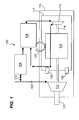
- Fig. 1 illustrates an exemplary embodiment of the present application, a gas cooled electric motor gas compressor 100.
- the gas cooled electric motor gas compressor 100 may include a gas feed 102, a gas treatment device 104, a gas cooler 106, an electric motor 108, a cooling gas compressor 110, and a compressor 112.
- the electric motor 108 may be connected to a shaft 114, which may impart mechanical energy from the electric motor 108 to the compressor 112 and the cooling gas compressor 110.
- the shaft 114 may include a single shaft or a common multi-piece shaft such that the electric motor 108, the compressor 112 and the cooling gas compressor 110 rotate together on a common drive train.
- the multi-piece shaft may be connected by a combination of flexible and rigid couplings, including, for example, a hirth serration.
- the electric motor 108 may be any of several electric motors known in the art that are used for gas compression applications. These motors may include, for example, induction motors, synchronous motors, permanent magnet motors and the like. In some embodiments, the electric motor may be a high-speed electric motor.
- the term "high-speed electric motor” is defined to include electric motors that are capable of operating at speeds in excess of those used for conventional operation at 50 or 60 Hz.
- the electric motor 108 and the compressor 112 may be located within a motor-compressor casing 116.
- the electric motor 108 and the cooling gas compressor 110 may be located within an internal casing 117, which may be located within the motor-compressor casing 116.
- the internal casing 117 may be sealed within the motor-compressor casing 116 by a plurality of internal seals 118, which are known in the art.
- the compressor 112 may be in fluid communication with the gas feed 102.
- the compressor 112 may be a compressor known in the art that is used for gas compression applications, such as axial compressors, radial compressors, axial-radial compressors and the like.
- the gas feed 102 may provide a supply of gas, such as natural gas or other types of gas for which compression may be necessary, to the compressor 112.
- the compressor 112 may be in fluid communication with a gas outlet 120, through which compressed gas may exit the compressor 112.
- the gas feed 102 also may be in fluid communication via a valve 122 with the gas treatment device 104.
- the gas treatment device 104 may treat an incoming supply of gas to remove corrosive materials, such as H 2 S or CO 2 , or other contaminants per methods known in the art. Gas treatment by the gas treatment device 104 may be accomplished through the use of absorption or adsorption or other similar processes.
- the gas treatment device 104 may be in fluid communication with the gas cooler 106.
- the gas cooler 106 may be any type of heat exchanger known in the art that may be used to remove heat from a flow of gas.
- the gas cooler 106 for example, may be a shell and tube, fin type, or other similar heat exchanger.
- the gas cooler 106 also may be in fluid communication with the cooling gas compressor 110.
- the cooling gas compressor 110 may compress a flow of gas it receives from the gas cooler 106 and then may direct the flow of compressed gas through the electric motor 108 per methods know in the art such that the flow of compressed gas removes excess heat from the electric motor 108 during operation. After the flow of compressed gas has moved through the electric motor 108, it may be directed from the electric motor 108 to the gas cooler 106.
- the gas cooled electric motor gas compressor 100 may operate as follows. A supply of gas may enter the gas cooled electric motor gas compressor 100 through the gas feed 102. A majority of the supply of gas may be directed to the compressor 112. The remaining portion of the supply of gas may be directed to the valve 122. The valve 122 may control the flow of gas to the gas treatment device 104.
- the electric motor 108 may drive the shaft 114, which may transfer mechanical energy to the compressor 112 and the cooling gas compressor 110.
- the compressor 112 may use the mechanical energy to compress the supply of gas pursuant to methods known in the art.
- the compressed gas then may exit the compressor through the gas outlet 120.
- a treated gas cooling circuit 124 may supply cool, non-corrosive gas to the electric motor 108 so that excessive heat may be removed from the electric motor 108 as it operates.
- the treated gas cooling circuit 124 may start at the cooling gas compressor 110 where a supply of treated gas is compressed. The supply of treated gas from the compressor then may be directed to the electric motor 108 where it may pass through the electric motor 108 to remove excessive heat per methods known in the art.
- the heated gas may be directed to the gas cooler 106, where it may be cooled by a heat exchanger within the gas cooler 106. The cooled supply of gas then may be directed to the cooling gas compressor 110, where the circuit may begin again.
- the treated gas used in the treated gas cooling circuit 124 may include gas that has been treated by the gas treatment device 104.
- the gas used in the treated gas cooling circuit 124 may first be directed to the gas treatment device 104.
- corrosive and/or abrasive impurities may be removed or greatly reduced such that when the gas is used within the electric motor 108 for cooling, sensitive parts within the electric motor are substantially protected from the corrosive and abrasive effects of exposure to untreated gas.
- the internal seals 118 are required only to seal against the pressure differential between the pressure within the internal casing 117 and pressure maintained between the internal casing 117 and the compressor-motor casing 116. This operational advantage allows the internal seals 118 to be of simpler design and generally require less maintenance. However, even with this reduced pressure differential, some gas leakage through the internal seals 118 from the treated gas cooling circuit 124 likely will be experienced during operation. Because the internal seals 118 are located within the motor-compressor casing 116, the gas generally should not leak to the environment.
- the pressure differential maintained between the motor-compressor casing 116 and the internal casing 117 i.e., the internal casing is maintained at a higher pressure
- the pressure differential maintained between the motor-compressor casing 116 and the internal casing 117 i.e., the internal casing is maintained at a higher pressure
- the compressor 112 where it may be compressed and exit through the gas outlet 120.
- the system may have a supply of treated make-up gas for the treated gas cooling circuit 124.
- control methods known in the art may periodically determine when make-up gas is needed due to leakage and may operated the valve 122 so that a supply of raw gas may be directed to the gas treatment device 104 and in turn, the gas cooler 106.
- the raw gas may be treated so that a supply of treated make-up gas then may be directed to the gas cooler 106 where it may be added to the supply of the gas in the treated gas cooling circuit 124.
- make-up gas may be added to the supply of gas used in the treated gas cooling circuit 124 to replace gas that is lost due to leakage. Further, only the small amount of gas that is periodically lost due to leakage has to treated by the gas treatment device 104, which efficiently reduces the usage of the gas treatment device 104.
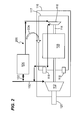
- Fig. 2 illustrates an alternative exemplary embodiment of the present application, a gas cooled electric motor gas compressor 200.
- the gas cooled electric motor gas compressor 200 may include a gas feed 102, a gas treatment device 104, an electric motor 108, a cooling gas compressor 110, and a compressor 112.
- the gas cooler 106 may be omitted in this embodiment.
- the electric motor 108 also may be connected to a shaft 114, which may impart mechanical energy from the electric motor 108 to the compressor 112 and the cooling gas compressor 110.
- the electric motor 108 and the compressor 112 may be located within a motor-compressor casing 116.
- the electric motor 108 and the cooling gas compressor 110 may be located within an internal casing 117, which is located within the motor-compressor case 116.
- the internal casing 117 may be sealed within the motor-compressor casing by a plurality of internal seals 118.
- the compressor 112 may be in fluid communication with the gas feed 102.
- the compressor 112 may be in fluid communication with a gas outlet 120, through which compressed gas may exit the compressor 112.
- the gas feed 102 also may be in fluid communication via a valve 122 with the gas treatment device 104.
- the gas treatment device 104 also may be in fluid communication with the cooling gas compressor 110, which may compress a flow of gas it receives from the gas treatment device 104 and then direct the flow of compressed gas through the electric motor 108 such that the flow of compressed gas removes excess heat from the electric motor 108 as it operates. After the flow of compressed gas has moved through the electric motor 108, it may be directed from the electric motor 108 to the supply of gas that is directed to the compressor 112.
- the gas cooled electric motor gas compressor 200 may operate as follows. A supply of gas may enter the gas cooled electric motor gas compressor 200 through the gas feed 102. A majority of the supply of gas may be directed to the compressor 110. The remaining portion of the supply of gas may be directed to the valve 122 which may control the flow of gas to the gas treatment device 104 per methods known in the art.
- the electric motor 108 may drive the shaft 114, which may transfer mechanical energy to the compressor 112 and the cooling gas compressor 110.
- the compressor 112 may use the mechanical energy to compress the supply of gas pursuant to methods known in the art.
- the gas then may exit the compressor through the gas outlet 120.
- a treated gas cooling circuit 224 may supply ambient, non-corrosive gas to the electric motor 108 so that excessive heat may be removed from the electric motor 108 as it operates.
- the treated gas cooling circuit 224 may start at the valve 122. Control methods known in the art may operate valve 122 such that an appropriate amount of raw cooling gas is bled from the raw gas supplied by gas feed 102. The supply of gas through the valve 122 then may be directed to the gas treatment device 104. In the gas treatment device 104, the raw gas may be treated such that corrosive and/or abrasive impurities may be removed or greatly reduced. Thus, this supply of cooling gas may be used to cool the electric motor 108 such that the electric motor 108 is substantially protected from the corrosive and abrasive effects of exposure to untreated gas.
- a supply of treated gas may be directed to the cooling gas compressor 110 where it may be compressed.
- the supply of treated gas from the cooling gas compressor 110 then may be directed through the electric motor 108 where it removes excessive heat per methods known in the art.
- the heated gas may be directed back to the supply of raw gas that is directed to the compressor 112.
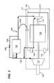
- Fig. 3 illustrates an alternative exemplary embodiment that is similar to the embodiment of Fig. 2, a gas cooled electric motor gas compressor 300.
- the gas cooled electric motor gas compressor 300 may include all of the components described in relation to the gas cooled electric motor gas compressor 200, including a gas feed 102, a gas treatment device 104, an electric motor 108, a cooling gas compressor 110, and a compressor 112.
- the gas cooled electric motor gas compressor 300 may include a treated gas bypass 302. Note that the treated gas bypass 302 also may be used in the system illustrated in Fig. 1 to bypass either the gas treatment device 104 prior to entering the gas cooler 106 or to bypass both the gas treatment device 104 and the gas cooler 106.
- the gas cooled electric motor gas compressor 300 may operate similarly to the gas cooled electric motor gas compressor 200.
- the treated gas bypass 302 may be used so that raw gas that is essentially clean, i.e., free from a significant level of impurities that could harm the internal components of the electric motor 108, may bypass the gas treatment device 104 when being used in the treated gas cooling circuit 224.
- the gas treatment device 104 may be bypassed such that the treated gas cooling circuit 224 is made more efficient.
- the valve 122 may be closed and a second valve 306 may be opened. In other embodiments where it is determined that the raw gas is essentially clean, the gas treatment device 104 and the valve 122 may be omitted altogether.
Landscapes
- Engineering & Computer Science (AREA)
- Mechanical Engineering (AREA)
- General Engineering & Computer Science (AREA)
- Physics & Mathematics (AREA)
- Thermal Sciences (AREA)
- Motor Or Generator Cooling System (AREA)
- Compressor (AREA)
- Structures Of Non-Positive Displacement Pumps (AREA)
Applications Claiming Priority (1)
| Application Number | Priority Date | Filing Date | Title |
|---|---|---|---|
| US11/583,266 US20080107547A1 (en) | 2006-10-19 | 2006-10-19 | Systems for cooling motors for gas compression applications |
Publications (1)
| Publication Number | Publication Date |
|---|---|
| EP1914429A2 true EP1914429A2 (de) | 2008-04-23 |
Family
ID=39030880
Family Applications (1)
| Application Number | Title | Priority Date | Filing Date |
|---|---|---|---|
| EP07254050A Withdrawn EP1914429A2 (de) | 2006-10-19 | 2007-10-12 | Motorenkühlung für Gasverdichtungsanlagen |
Country Status (3)
| Country | Link |
|---|---|
| US (1) | US20080107547A1 (de) |
| EP (1) | EP1914429A2 (de) |
| AU (1) | AU2007229355A1 (de) |
Cited By (4)
| Publication number | Priority date | Publication date | Assignee | Title |
|---|---|---|---|---|
| CN101975175A (zh) * | 2010-08-11 | 2011-02-16 | 西安胜唐鼓风机有限公司 | 一种带中间冷却器的同轴离心压缩机 |
| WO2012058069A3 (en) * | 2010-10-27 | 2012-07-05 | Dresser-Rand Company | System and method for rapid pressurization of a motor/bearing cooling loop for a hermetically sealed motor/compressor system |
| WO2013028594A3 (en) * | 2011-08-24 | 2013-04-25 | Dresser-Rand Company | Efficient and reliable subsea compression system |
| EP2715141A4 (de) * | 2011-06-01 | 2014-11-05 | Dresser Rand Co | Unterwasser-motorkompressor-kühlsystem |
Families Citing this family (7)
| Publication number | Priority date | Publication date | Assignee | Title |
|---|---|---|---|---|
| US20110315230A1 (en) * | 2010-06-29 | 2011-12-29 | General Electric Company | Method and apparatus for acid gas compression |
| US20130315755A1 (en) * | 2012-05-23 | 2013-11-28 | Ilia Oxman | Temperature control system for a machine and methods of operating same |
| JP6460773B2 (ja) * | 2014-12-19 | 2019-01-30 | 株式会社マーレ フィルターシステムズ | ターボチャージャ |
| JP2016156282A (ja) * | 2015-02-23 | 2016-09-01 | 三菱重工業株式会社 | 圧縮機システム |
| FR3064981B1 (fr) * | 2017-04-05 | 2019-05-03 | Zodiac Aerotechnics | Systeme d'inertage et procede de generation d'un gaz d'inertage dans un aeronef, fonctionnant sans prelevement d'air exterieur |
| JP7103263B2 (ja) * | 2019-02-20 | 2022-07-20 | 株式会社豊田自動織機 | ターボ式流体機械 |
| CN113048075A (zh) * | 2021-03-16 | 2021-06-29 | 西安交通大学 | 一种带离心油泵的燃料电池用空气增压系统 |
Family Cites Families (8)
| Publication number | Priority date | Publication date | Assignee | Title |
|---|---|---|---|---|
| US4358254A (en) * | 1978-09-01 | 1982-11-09 | Tecumseh Products Company | Variable capacity compressor |
| US6065297A (en) * | 1998-10-09 | 2000-05-23 | American Standard Inc. | Liquid chiller with enhanced motor cooling and lubrication |
| US6176092B1 (en) * | 1998-10-09 | 2001-01-23 | American Standard Inc. | Oil-free liquid chiller |
| US6672065B1 (en) * | 1999-09-15 | 2004-01-06 | Ewan Choroszylow | Multiple stage compressor with rotors using rollers |
| JP3976459B2 (ja) * | 1999-11-18 | 2007-09-19 | 株式会社荏原製作所 | フッ素含有化合物を含む排ガスの処理方法及び装置 |
| JP2001193639A (ja) * | 2000-01-11 | 2001-07-17 | Toyota Autom Loom Works Ltd | 電動斜板圧縮機 |
| US20040149007A1 (en) * | 2003-02-04 | 2004-08-05 | Stephen Staphanos | Sample handling system with solvent washing |
| US7181928B2 (en) * | 2004-06-29 | 2007-02-27 | York International Corporation | System and method for cooling a compressor motor |
-
2006
- 2006-10-19 US US11/583,266 patent/US20080107547A1/en not_active Abandoned
-
2007
- 2007-10-12 EP EP07254050A patent/EP1914429A2/de not_active Withdrawn
- 2007-10-17 AU AU2007229355A patent/AU2007229355A1/en not_active Abandoned
Cited By (6)
| Publication number | Priority date | Publication date | Assignee | Title |
|---|---|---|---|---|
| CN101975175A (zh) * | 2010-08-11 | 2011-02-16 | 西安胜唐鼓风机有限公司 | 一种带中间冷却器的同轴离心压缩机 |
| WO2012058069A3 (en) * | 2010-10-27 | 2012-07-05 | Dresser-Rand Company | System and method for rapid pressurization of a motor/bearing cooling loop for a hermetically sealed motor/compressor system |
| US9726196B2 (en) | 2010-10-27 | 2017-08-08 | Dresser-Rand Company | System and cooling for rapid pressurization of a motor-bearing cooling loop for a hermetically sealed motor/compressor system |
| EP2715141A4 (de) * | 2011-06-01 | 2014-11-05 | Dresser Rand Co | Unterwasser-motorkompressor-kühlsystem |
| WO2013028594A3 (en) * | 2011-08-24 | 2013-04-25 | Dresser-Rand Company | Efficient and reliable subsea compression system |
| US9488180B2 (en) | 2011-08-24 | 2016-11-08 | Dresser-Rand Company | Efficient and reliable subsea compression system |
Also Published As
| Publication number | Publication date |
|---|---|
| AU2007229355A1 (en) | 2008-05-08 |
| US20080107547A1 (en) | 2008-05-08 |
Similar Documents
| Publication | Publication Date | Title |
|---|---|---|
| AU2007229355A1 (en) | Systems for cooling motors for gas compression applications | |
| CN102741536B (zh) | 热力发动机和热电系统及方法 | |
| CN109424375B (zh) | 具有磁轴承冷却的涡轮机系统和方法 | |
| EP2715141B1 (de) | Unterwasser-motorkompressor-kühlsystem | |
| RU2429387C2 (ru) | Способ и устройство для защиты компрессорных модулей от притока загрязненного газа | |
| EP3372835B1 (de) | Kompressormodul für gaskompression und damit ausgestatteter kompressor | |
| US11585245B2 (en) | Power generation system and method to generate power by operation of such power generation system | |
| EP2789855B1 (de) | Temperaturregelung für Verdichter | |
| US9372022B2 (en) | Compressor waste heat driven cooling system | |
| US20130315755A1 (en) | Temperature control system for a machine and methods of operating same | |
| RU2670994C2 (ru) | Роторная машина и способ теплообмена в роторной машине | |
| CN106062494A (zh) | 用于冷却和/或低温液化的装置和方法 | |
| RU2006680C1 (ru) | Газоперекачивающий агрегат | |
| JP4908953B2 (ja) | スクリュ圧縮機 | |
| WO2007055589A1 (en) | Pressure and leakage control in rotating equipment for subsea compression | |
| JP4314131B2 (ja) | エンジン駆動型オイルフリー圧縮機の冷却機構 | |
| RU2565648C2 (ru) | Способ и устройство для сжатия кислого газа | |
| WO2007067060A1 (en) | Cooling system for an electric motor, and a drive system for driving an impeller | |
| WO2007073195A1 (en) | Pump unit and method for pumping a well fluid | |
| CN113661307A (zh) | 发电系统和通过操作这种发电系统来发电的方法 |
Legal Events
| Date | Code | Title | Description |
|---|---|---|---|
| PUAI | Public reference made under article 153(3) epc to a published international application that has entered the european phase |
Free format text: ORIGINAL CODE: 0009012 |
|
| AK | Designated contracting states |
Kind code of ref document: A2 Designated state(s): AT BE BG CH CY CZ DE DK EE ES FI FR GB GR HU IE IS IT LI LT LU LV MC MT NL PL PT RO SE SI SK TR |
|
| AX | Request for extension of the european patent |
Extension state: AL BA HR MK RS |
|
| STAA | Information on the status of an ep patent application or granted ep patent |
Free format text: STATUS: THE APPLICATION IS DEEMED TO BE WITHDRAWN |
|
| 18D | Application deemed to be withdrawn |
Effective date: 20110503 |