EP1914461A1 - Systeme de fixation de conduites à un élément structurel - Google Patents
Systeme de fixation de conduites à un élément structurel Download PDFInfo
- Publication number
- EP1914461A1 EP1914461A1 EP07118735A EP07118735A EP1914461A1 EP 1914461 A1 EP1914461 A1 EP 1914461A1 EP 07118735 A EP07118735 A EP 07118735A EP 07118735 A EP07118735 A EP 07118735A EP 1914461 A1 EP1914461 A1 EP 1914461A1
- Authority
- EP
- European Patent Office
- Prior art keywords
- mounting
- rail
- modules
- fastening
- pipe
- Prior art date
- Legal status (The legal status is an assumption and is not a legal conclusion. Google has not performed a legal analysis and makes no representation as to the accuracy of the status listed.)
- Withdrawn
Links
Images


Classifications
-
- F—MECHANICAL ENGINEERING; LIGHTING; HEATING; WEAPONS; BLASTING
- F16—ENGINEERING ELEMENTS AND UNITS; GENERAL MEASURES FOR PRODUCING AND MAINTAINING EFFECTIVE FUNCTIONING OF MACHINES OR INSTALLATIONS; THERMAL INSULATION IN GENERAL
- F16L—PIPES; JOINTS OR FITTINGS FOR PIPES; SUPPORTS FOR PIPES, CABLES OR PROTECTIVE TUBING; MEANS FOR THERMAL INSULATION IN GENERAL
- F16L3/00—Supports for pipes, cables or protective tubing, e.g. hangers, holders, clamps, cleats, clips, brackets
- F16L3/22—Supports for pipes, cables or protective tubing, e.g. hangers, holders, clamps, cleats, clips, brackets specially adapted for supporting a number of parallel pipes at intervals
- F16L3/223—Supports for pipes, cables or protective tubing, e.g. hangers, holders, clamps, cleats, clips, brackets specially adapted for supporting a number of parallel pipes at intervals each support having one transverse base for supporting the pipes
Definitions
- the present invention relates to a system for securing pipes to a supporting structural element, which system comprises mounting modules, each provided with at least one pipe seat designed for receiving a pipe.
- pipe is also intended to include flexible hoses.
- Some apparatuses for example hydraulic cranes, are provided with extensive pipe systems which can comprise pipes for conveying hydraulic oil or compressed air and pipes which enclose electric cables. These pipes are often arranged in parallel with each other and are by means of pipe clamps or like attached to a supporting structural element of the apparatus.
- the number of pipes often becomes large for a hydraulic crane and the available surface for attachment of the pipes is generally limited. To install a pipe set on a hydraulic crane is therefore often a relatively troublesome and time-consuming work.
- the US patent document US 3 216 683 A describes a system for attachment of pipes to a supporting structural element, which system comprises mutually interacting mounting modules, each provided with a pipe seat designed for receiving a pipe.
- the object of the present invention is to achieve a further development of a pipe securing system of the type indicated above, so as to provide a pipe securing system with a design and function which in at least some aspects provide an advantage compared to previously known systems of the type here in question.
- the inventive pipe securing system comprises mounting modules, each provided with at least one pipe seat designed for receiving a pipe.
- These mounting modules are provided with coupling members which, by way of mutual force fit and/or positive locking, allow mutual coupling of individual mounting modules in a row to an elongated, self-supporting and shape stable mounting rail with the pipe seats of the mounting modules included in the mounting rail extending parallel to each other, perpendicularly to the mounting rail's longitudinal axis.
- a suitable number of mounting modules to a mounting rail which can be handled as an independent fastening element and be applied against a set of parallel pipes in order to secure these pipes to an underlying structural element.
- the individual mounting modules do consequently not need to be handled and secured to the structural element one by one, but can instead be handled and secured to the structural element as a joint unit in the form of said mounting rail.
- the installation work is in this way facilitated.
- the mounting modules are coupled together and hold on to each other by mutual force fit and/or positive locking between their mutually interacting coupling members, there is no need for separate fastening members in the form of screws, bolts or the like in order to couple the mounting modules to each other.
- the respective mounting module is provided with a male-shaped coupling member at a first end and a corresponding female-shaped coupling member at the opposite second end.
- the male-shaped coupling member of a mounting module is in this case connectable to the female-shaped coupling member of each of the other mounting modules included in the system.
- At least some of the mounting modules included in the system are each provided with two pipe seats designed for receiving a respective pipe.
- These mounting modules are suitable for installing pipes arranged in pairs.
- Such pipes arranged in pairs may for instance comprise a feeding line for hydraulic oil or compressed air and an associated return line, and are inter alia commonly occurring in hydraulic cranes.
- the system comprises two or more different sets of mounting modules, where the pipe seats of the mounting modules in one set have a dimensioning which differs from the dimensioning of the pipe seats of the mounting modules in the other sets.
- At least some of the mounting modules included in the system are each on its top side provided with at least one guide groove for a pipe, the respective guide groove extending parallel to the mounting module's pipe seat or pipe seats.
- the respective guide groove extending parallel to the mounting module's pipe seat or pipe seats.
- the system comprises elongated fastening rails, each intended to be attached to a supporting structural element and being provided with threaded holes distributed along the fastening rail with a mutual distance which corresponds to the mutual distance between the through holes in a mounting rail formed by mutually coupled mounting modules, the respective threaded hole being designed for receiving a threaded fastening member extending through one of said through holes in order to allow clamping of said mounting rail to the fastening rail.
- a mounting rail formed by two or more mounting modules is with advantage secured to a desired structural element by way of such a fastening rail, the fastening rail being first mounted to the structural element, for instance by welding, and the mounting rail being then fastened to the fastening rail by means of two or more threaded fastening members.
- the fastening rails are provided in the form of an elongated fastening rail strip, which is provided with transversal notches in order to facilitate splitting of the fastening rail strip into individual fastening rails.
- the fastening rails may consequently be provided as piece goods in the form of said fastening rail strip, from which a fastening rail of a desired length, adapted to a mounting rail, can be detached.
- the system comprises rail modules, each comprising at least one threaded hole of said kind, the rail modules being provided with coupling members which allow mutual coupling of individual rail modules in a row to an elongated fastening rail.
- the expression “self supporting and shape stable mounting rail” refers to a mounting rail which has sufficient stiffness and stability to keep its shape when exposed to influence with forces of smaller magnitude, so that the mounting rail for instance can be lifted at one end on its own without collapsing.
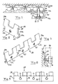
- FIGs 1 and 2 a variant of a mounting module 1 included in a system according to the present invention is illustrated.
- the mounting module 1 is provided with two pipe seats 2a, 2b on its underside 5d, which are designed for receiving one pipe each in order to fix the respective pipe to a supporting structural element.
- the inventive system may also comprise mounting modules which are provided with only one pipe seat or more than two pipe seats.
- the respective pipe seat 2a, 2b has an essentially concavely curved support surface 3 with an arched profile so as to essentially connect to the envelope surface of a circular pipe intended to be received in the pipe seat.
- the mounting module 1 is provided with coupling members 4a, 4b, each connectable with a corresponding coupling member 4b, 4a of another mounting module of the same type, and by that allow mutual coupling of individual mounting modules 1 of the same type in a row to an elongated self-supporting and shape stable mounting rail 10 (see Fig 3a) with the pipe seats 2a, 2b of the mounting modules included in the mounting rail extending parallel to each other, perpendicularly to the mounting rail's longitudinal axis.
- the mutually interacting coupling members 4a, 4b of two mutually coupled mounting modules 1 are designed to hold on to each other by mutual force fit and/or positive locking, so that the coupling members and the mounting modules thereby remain held together after having been coupled, until a separating force of sufficient magnitude is applied to the mounting modules.
- the mounting module 1 is provided with a male-shaped first coupling member 4a at a first end and a corresponding female-shaped second coupling member 4b at the opposite second end.
- the male-shaped coupling member 4a of a mounting module 1 of the type illustrated in Figs 1 and 2 is receivable with force fit in the female-shaped coupling member 4b of each of the other mounting modules of the same type included in the system.
- the female-shaped coupling member 4b has the shape of an elongated recess extending in the mounting module's longitudinal direction, which has an entrance opening 6 arranged in one 5b of the end surfaces of the mounting module, via which entrance opening a corresponding male-shape coupling member 4a of another mounting module is insertable into the recess in the mounting modules' longitudinal direction.
- the male-shaped coupling member 4a has the shape of a projection extending in the mounting module's longitudinal direction, which projection projects from the opposite end surface 5a of the mounting module.
- Two mounting modules 1 of the type illustrated in Figs 1 and 2 are thus connectable to each other by pressing the male-shaped coupling member 4a of one of the mounting modules into the female-shaped coupling member 4b of the other mounting module via said entrance opening 6.
- the recess 4b is also open towards the top side 5c of the mounting module and has the shape of a truncated triangle with the peak facing the top side 5c of the mounting module, the male-shaped coupling member 4a having a corresponding shape.
- a mounting rail 10 formed by three coupled mounting modules 1 of the type illustrated in Figs 1 and 2 is shown in Fig 3a.
- a pulling apart of the mounting modules in the mounting rail's longitudinal direction is counteracted; and by positive locking between the interacting coupling members 4a, 4b of the mutually coupled mounting modules 1, a pulling apart of the mounting modules in the mounting rail's cross-direction is counteracted.
- FIG. 10 An alternative variant of a mounting module 1' for a system according to the present invention is illustrated in Fig 10. Also this mounting module 1' is provided with a first coupling member 4a' at a first end, and a corresponding second coupling member 4b' at the opposite second end.
- the first coupling member 4a' of a mounting module 1' of the type illustrated in Fig 10 is receivable in the second coupling member 4b' in each of the mounting modules of the same type included in the system.
- the first coupling member 4a' comprises an upwards directed projection 41a extending in the mounting module's cross-direction and a groove 42a formed between this projection 41a and the end surface 5a of the mounting module
- the other coupling member 4b' comprises a downwards directed projection 41 b extending in the mounting module's cross-direction and a groove 42b formed between this projection 41b and the end surface 5b of the mounting module.
- Two mounting modules 1' of the type illustrated in Fig 10 are connectable with each other in that the projection 41 a, 41 b of each of the two interacting coupling members 4a', 4b' is inserted into the groove 42b, 42a of the other coupling member by displacement of the mounting modules towards each other in the mounting modules' cross-direction.
- a mounting rail 10 formed by two coupled mounting modules 1' of the type illustrated in Fig 10 is shown in Fig 11.
- a pulling apart of the mounting modules in the mounting rail's longitudinal direction is counteracted; and by clamp action between the interacting coupling members 4a', 4b' of the mutually coupled mounting modules 1', a pulling apart of the mounting modules in the mounting rail's cross-direction is counteracted.
- Mounting modules for a system according to the present invention may naturally also have other designs than the two variants described above, and may have coupling members which interact with each other in other ways than described above.
- the main thing is that the mounting modules easily and quickly can be coupled together to an elongated self-supporting and shape stable mounting rail without requiring separate fastening members in the form of screws, bolts or the like.
- the first coupling members 4a, 4a' and the second coupling members 4b, 4b' could be provided with mutually interacting snap members (not shown) so as to allow the first coupling member 4a, 4a' of one of the mounting modules included in the system to engage with snap effect in the second coupling member 4b, 4b' of each of the other mounting modules included in the system by means of said mutually interacting snap members.
- the snap members may for instance consist of a projection in one of the coupling members and a groove or recess in the other coupling member, which are so designed that the projection will come into engagement with the groove/recess when the coupling members have taken the intended coupling position in relation to each other.
- the inventive system may with advantage comprise two or more different sets of mounting modules where the pipe seats 2a, 2b of the mounting modules in one set have a dimensioning which differs from the dimensioning of the pipe seats of the mounting modules in the other sets, whereby it becomes possible to adapt the mounting rails to pipes with mutually different outer diameter.
- the mounting modules in the respective set suitably have a colour marking which differs from corresponding colour markings of the mounting modules in the other sets, so that it becomes possible to quickly and easily see which type of pipe a certain mounting module is intended for.
- the respective mounting module 1, 1' is provided with a through hole 7 designed for receiving an elongated fastening member 11 (see Figs 4 and 5) in order to allow securing of the mounting module to a supporting structural element 30.
- the mounting modules 1, 1' may with advantage be made of plastic.
- the inventive system also suitably comprises elongated fastening rails 20, a mounting rail 10 of the above-mentioned type being intended to be secured to a supporting structural element 30 via such a fastening rail 20.
- the fastening rail 20 is provided with threaded holes 21 distributed along the fastening rail with a mutual distance which corresponds to the mutual distance between the through holes 7 in a mounting rail 10 formed by mutually coupled mounting modules 1, 1', the respective threaded hole 21 being designed for receiving a threaded part of a fastening member 11 in the form of a threaded screw or bolt extending through one of said through holes 7 in order to allow fastening of the mounting rail 10 to the fastening rail 20.
- the fastening rails 20 may with advantage be formed by individual rail modules 22, for instance of the type illustrated in Fig 6, each of which comprising at least one threaded hole 21 of the type mentioned above.
- the rail modules 22 are provided with coupling members 23a, 23b which allow mutual coupling of individual rail modules 22 in a row to an elongated fastening rail 20 (see Fig 7).
- the respective rail module 22 is provided with a male-shaped coupling member 23a at a first end and a corresponding female-shaped coupling member 23b at the opposite second end.
- the male-shaped coupling member 23a of a rail module 22 of the type illustrated in Figs 7 and 8 is receivable in the female-shaped coupling member 23b of each of the other rail modules of the same type included in the system.
- the female-shaped coupling member 23b has the shape of a recess arranged in one short side 24b of the rail module.
- the male-shaped coupling member 23a has the shape of a projection, which projects from the opposite short side 24a of the rail module.
- Two rail modules 22 of the type illustrated in Fig 7 are thus connectable to each other by insertion of the male-shaped coupling member 23a of one of the rail modules into the female-shaped coupling member 23b of the other rail module.
- a fastening rail 20 formed by three coupled rail modules 22 of the type illustrated in Fig 7 is shown in Fig 8.
- the fastening rails could alternatively be provided in the form of an elongated fastening rail strip 25 provided with transversal notches 26, for instance in the form of breaking notches, so as to facilitate splitting of the fastening rail strip into individual fastening rails 20, as illustrated in Fig 9.
- the respective fastening rail 20 is intended to constitute a counter member for the pipes 40 which are braced against a supporting structural element 30 by means of a mounting rail 10 and is at the same time acting as a holder for the mounting rail.
- the pipes 40 are clamped between the mounting rail 10 and the associated fastening rail 20 by tightening of fastening members 11 of the type mentioned above, as illustrated in Figs 4, 5 and 8.
- the respective fastening member 11 is brought through one of the through holes 7 of the mounting rail 10 and is secured by screwing to one of the threaded holes 21 of the associated fastening rail.
- the head 12 of the fastening member bears against a shoulder 13 formed by a depression around the hole 7 and thereby exerts a compressive force against the mounting rail 10, which presses this in the direction towards the fastening rail 20.
- the mounting modules 1, 1' are on their top side 5c provided with guide grooves 9 for pipes, the respective guide groove 9 extending parallel to the mounting module's pipe seats 2a, 2b.
- the respective guide groove 9 is arranged opposite a pipe seat 2a, 2b of the associated mounting module and straight above the central line of this pipe seat.
- longer fastening members 11' are used, which extend through holes 7, lying in line with each other, in all these mounting rails, and which are secured by screwing to one of the threaded holes 21 of an associated fastening rail 20.
- the fastening rail 20 is suitably of metal so as to make it possible to secure it to a metal structural element 30 by welding, as illustrated in Fig 8.
- the rail modules and the fastening rail strip 25, respectively has an essentially flat base part 27 where said threaded holes 21 are arranged and a flange part 28 projecting at an angle from one of the long sides of the base part, via which flange part a fastening rail 20 formed by rail modules or by the fastening rail strips is intended to be secured to a desired structural element 30.
- the inventive system is for instance very advantageous to use for installing pipes in a pipe system of a hydraulic crane.
Landscapes
- Engineering & Computer Science (AREA)
- General Engineering & Computer Science (AREA)
- Mechanical Engineering (AREA)
- Supports For Pipes And Cables (AREA)
- Mutual Connection Of Rods And Tubes (AREA)
Applications Claiming Priority (1)
| Application Number | Priority Date | Filing Date | Title |
|---|---|---|---|
| SE0602200A SE0602200L (sv) | 2006-10-20 | 2006-10-20 | System för fästande av rör vid ett bärande konstruktionselement, vilket system innefattar fästmoduler |
Publications (1)
| Publication Number | Publication Date |
|---|---|
| EP1914461A1 true EP1914461A1 (fr) | 2008-04-23 |
Family
ID=38962940
Family Applications (1)
| Application Number | Title | Priority Date | Filing Date |
|---|---|---|---|
| EP07118735A Withdrawn EP1914461A1 (fr) | 2006-10-20 | 2007-10-18 | Systeme de fixation de conduites à un élément structurel |
Country Status (2)
| Country | Link |
|---|---|
| EP (1) | EP1914461A1 (fr) |
| SE (1) | SE0602200L (fr) |
Cited By (3)
| Publication number | Priority date | Publication date | Assignee | Title |
|---|---|---|---|---|
| WO2013191848A1 (fr) * | 2012-06-19 | 2013-12-27 | Frank Notaro | Système de fixation modulaire |
| CN104180072A (zh) * | 2014-07-28 | 2014-12-03 | 成都高普石油工程技术有限公司 | 大容量凹槽型石油管道架的垫梁 |
| US10161542B1 (en) | 2017-11-10 | 2018-12-25 | Cnh Industrial America Llc | Mounting hard lines to a vehicle frame |
Citations (4)
| Publication number | Priority date | Publication date | Assignee | Title |
|---|---|---|---|---|
| DE8809540U1 (de) * | 1988-07-26 | 1988-09-15 | Böhm Kunststoffe GmbH, 95126 Schwarzenbach a d Saale | Abstandshalter |
| DE8801062U1 (de) * | 1988-01-29 | 1989-06-15 | Robert Bosch Gmbh, 7000 Stuttgart | Klemmleiste zur Fixierung freiliegender Stränge |
| EP0816735A1 (fr) * | 1996-06-25 | 1998-01-07 | Toyota Yuki Co., Ltd. | Système de fixation pour tuyaux flexibles |
| DE29805495U1 (de) * | 1998-03-26 | 1998-05-28 | OBO Bettermann GmbH & Co. KG, 58710 Menden | Klemmschelle aus Kunststoff |
-
2006
- 2006-10-20 SE SE0602200A patent/SE0602200L/xx not_active IP Right Cessation
-
2007
- 2007-10-18 EP EP07118735A patent/EP1914461A1/fr not_active Withdrawn
Patent Citations (4)
| Publication number | Priority date | Publication date | Assignee | Title |
|---|---|---|---|---|
| DE8801062U1 (de) * | 1988-01-29 | 1989-06-15 | Robert Bosch Gmbh, 7000 Stuttgart | Klemmleiste zur Fixierung freiliegender Stränge |
| DE8809540U1 (de) * | 1988-07-26 | 1988-09-15 | Böhm Kunststoffe GmbH, 95126 Schwarzenbach a d Saale | Abstandshalter |
| EP0816735A1 (fr) * | 1996-06-25 | 1998-01-07 | Toyota Yuki Co., Ltd. | Système de fixation pour tuyaux flexibles |
| DE29805495U1 (de) * | 1998-03-26 | 1998-05-28 | OBO Bettermann GmbH & Co. KG, 58710 Menden | Klemmschelle aus Kunststoff |
Cited By (3)
| Publication number | Priority date | Publication date | Assignee | Title |
|---|---|---|---|---|
| WO2013191848A1 (fr) * | 2012-06-19 | 2013-12-27 | Frank Notaro | Système de fixation modulaire |
| CN104180072A (zh) * | 2014-07-28 | 2014-12-03 | 成都高普石油工程技术有限公司 | 大容量凹槽型石油管道架的垫梁 |
| US10161542B1 (en) | 2017-11-10 | 2018-12-25 | Cnh Industrial America Llc | Mounting hard lines to a vehicle frame |
Also Published As
| Publication number | Publication date |
|---|---|
| SE530259C2 (sv) | 2008-04-15 |
| SE0602200L (sv) | 2008-04-15 |
Similar Documents
| Publication | Publication Date | Title |
|---|---|---|
| US8770885B2 (en) | Wedge clamp | |
| US9239067B2 (en) | Sway brace attachment | |
| EP0857257B1 (fr) | Ameliorations apportees aux dispositifs de montage par serrage ou les concernant | |
| JP6130381B2 (ja) | パイプ間ブレース組立体 | |
| US5595363A (en) | Plastic pipe beam support | |
| EP1978288B1 (fr) | Fixation de tuyau à fermeture rapide | |
| US7726922B2 (en) | Quick release support post and associated method | |
| EP3237777B1 (fr) | Perfectionnements apportés ou se rapportant à des dispositifs de serrage | |
| WO2009042626A1 (fr) | Support de câble à fixation rigide pour canalisation comportant au moins trois surfaces latérales plates | |
| KR102555178B1 (ko) | 건물 내의 비-구조적 구성 요소용 내진 클램프 | |
| US5259165A (en) | Supporting metal fittings for double beams | |
| US10498123B2 (en) | Support bracket for mounting octagonal boxes on furring channels | |
| CZ20003361A3 (en) | Dead-end clamp for an insulated overhead cable, especially a bundle assembled overhead cable | |
| KR100935436B1 (ko) | 사이드클램프조립체 | |
| US20080203242A1 (en) | Spacer Assembly | |
| KR100710835B1 (ko) | 파이프 고정용 클램핑 장치 | |
| AU2010200780A1 (en) | Fastening device for placement on a mounting rail | |
| KR102026991B1 (ko) | 건물 배관 내진설계 지지 구조물 | |
| EP3999763B1 (fr) | Dispositif de serrage de poutre, et ensemble montage | |
| KR101916114B1 (ko) | 배관용 파이프 행거 | |
| EP2156083B1 (fr) | Bride pour la suspension d'un conduit | |
| US8096518B1 (en) | Truss mounted support system | |
| CN113823968B (zh) | 一种接线结构 | |
| US10024492B1 (en) | Cable-mounted traffic control device support bracket with strut member adapter | |
| US20080011908A1 (en) | Hanger clamp with hanger strap |
Legal Events
| Date | Code | Title | Description |
|---|---|---|---|
| PUAI | Public reference made under article 153(3) epc to a published international application that has entered the european phase |
Free format text: ORIGINAL CODE: 0009012 |
|
| AK | Designated contracting states |
Kind code of ref document: A1 Designated state(s): AT BE BG CH CY CZ DE DK EE ES FI FR GB GR HU IE IS IT LI LT LU LV MC MT NL PL PT RO SE SI SK TR |
|
| AX | Request for extension of the european patent |
Extension state: AL BA HR MK RS |
|
| AKX | Designation fees paid | ||
| REG | Reference to a national code |
Ref country code: DE Ref legal event code: 8566 |
|
| STAA | Information on the status of an ep patent application or granted ep patent |
Free format text: STATUS: THE APPLICATION IS DEEMED TO BE WITHDRAWN |
|
| 18D | Application deemed to be withdrawn |
Effective date: 20081024 |