EP1914501A1 - Arme semi-automatique - Google Patents
Arme semi-automatique Download PDFInfo
- Publication number
- EP1914501A1 EP1914501A1 EP06122647A EP06122647A EP1914501A1 EP 1914501 A1 EP1914501 A1 EP 1914501A1 EP 06122647 A EP06122647 A EP 06122647A EP 06122647 A EP06122647 A EP 06122647A EP 1914501 A1 EP1914501 A1 EP 1914501A1
- Authority
- EP
- European Patent Office
- Prior art keywords
- receiver
- magazine
- cylinder
- barrel
- tube
- Prior art date
- Legal status (The legal status is an assumption and is not a legal conclusion. Google has not performed a legal analysis and makes no representation as to the accuracy of the status listed.)
- Withdrawn
Links
Images


Classifications
-
- F—MECHANICAL ENGINEERING; LIGHTING; HEATING; WEAPONS; BLASTING
- F41—WEAPONS
- F41A—FUNCTIONAL FEATURES OR DETAILS COMMON TO BOTH SMALLARMS AND ORDNANCE, e.g. CANNONS; MOUNTINGS FOR SMALLARMS OR ORDNANCE
- F41A9/00—Feeding or loading of ammunition; Magazines; Guiding means for the extracting of cartridges
- F41A9/61—Magazines
- F41A9/64—Magazines for unbelted ammunition
- F41A9/72—Tubular magazines, i.e. magazines containing the ammunition in lengthwise tandem sequence
-
- F—MECHANICAL ENGINEERING; LIGHTING; HEATING; WEAPONS; BLASTING
- F41—WEAPONS
- F41A—FUNCTIONAL FEATURES OR DETAILS COMMON TO BOTH SMALLARMS AND ORDNANCE, e.g. CANNONS; MOUNTINGS FOR SMALLARMS OR ORDNANCE
- F41A9/00—Feeding or loading of ammunition; Magazines; Guiding means for the extracting of cartridges
- F41A9/01—Feeding of unbelted ammunition
- F41A9/02—Feeding of unbelted ammunition using wheel conveyors, e.g. star-wheel-shaped conveyors
Definitions
- the invention concerns to semi-automatic shotguns for military or police use.
- the known semi - automatic shotguns have a restricted loading capacity since, without modifying too much the desired size of a modern fighting shotgun, they can carry a maximum of nine or ten cartridges. This is because the cartridges are lodged aligned lengthwise in a tube that the weapon has under the barrel.
- the actual function of the magazine tube in standard shotguns is to give resistance to their structure.
- the rear end of the barrel floats inside the receiver and becomes firm actually because it is attached to the front end of the magazine tube. So, if the magazine tube is weakened or eliminated, the barrel will be assembled without the necessary firmness.
- the easier cocking or uncocking of the shotguns in the field is mostly searched by the users.
- the known shotguns are not so easy to cock or uncock in the field.
- the present invention is designed to find the solution to the prior art problems.
- the weapons were heavier and uncomfortable to carry and take from one place to another. Thus, the inventor realized that they were not good solutions.
- the invention presented in this patent document is a new design of semi - automatic shotgun which incorporates the cartridges loading system described in convinced Release U 3714 and makes it possible to use it properly. Said system solves the two problems by providing the necessary firmness and stability in order to operate the weapon, and by achieving an ergonomic, light, easy to carry design of semi - automatic shotgun for police and military use.
- this invention proposes a weapon that is mounted from below so modifying the way of its manufacture.
- the invention is a new design of semi - automatic shotgun whose main feature is an in - between connection steel part which fixes de barrel to the receiver.
- This steel part plays three roles. Firstly, it enables the magazine to float. Secondly, the barrel can be firmly attached to the receiver, thus providing stability. Thirdly, it works as a lock between the steel bolt and the barrel, so that it resists the explosion when the gun is fired, providing firmness. The firmness does not rely on an attached tube as in standard shotguns.
- connection steel part is tube shaped. Its front end is screwed to the barrel, whereas its rear end lodges the bolt head, which is locked inside by two small balls which fit into cavities specially cut in the part. Transversely it comprises a perforated rectangular steel plate which is fixed to the end of the receiver by screws.
- the barrel is screwed to the steel part, which, in turn, is fixed to the receiver by screws, preferably five of them.
- the cartridges loading system is disclosed in convincedan Record U 3714.
- the mechanism which makes said cartridges loading system work consists in a receiver that contains the bolt, a detachable trigger assembly and a four - canal cylinder connected to a cylinder hand, placed at the end of a two - axle pivot.
- the detachable trigger assembly contains the shots system, a two - axle pivot lever, an operating driving arm thereof, a fixed lever.
- the trigger assembly is detachable as one unit.
- the cylinder is made of plastic with four longitudinal canals symmetrically cut in their outer surface, which have a semicircular section. The cylinder rotates automatically by means of the two - axle pivot lever when the gun is fired.
- the rotation mechanism of the cylinder is a result of changing the movement of the bolt from horizontal into vertical, when the pivot balances firstly on a front axle, and secondly on a rear axle.
- the bolt pushes the two - axle pivot lever by means of the operating driving arm contained into the trigger, the fixed lever located at the end of the two - axle pivot lever enables the rotation of the cylinder.
- the cylinder turns 90° clockwise every time the gun is shot.
- the bolt slides inside a tube that goes through the receiver longitudinally, together with its inner pieces, inertial mass, nut, small balls and firing pin.
- the magazine consists of parallel tubes of said cartridges loading system that surround the barrel, encircling its sides and lower part.
- the magazine is fixed to the gun between the front side of the receiver and a lock with a handle fitted in the barrel near the front end.
- the retention of the cartridges inside the tubes is done by means of three metallic nails, which emerge each from one tube and retain them by the shell head. The nails hold the shell head of the last cartridge, preventing the springs from dislodging them while the magazine is out of the shotgun.
- the retaining metal nails hide and release the cartridges.
- the springs push and enable a cartridge from each tube to enter each canal of the cylinder through openings made into the front side of the receiver under the barrel.
- the bolt which is aligned with the chamber goes through the upper canal of the cylinder. It remains empty while the others have one cartridge each.
- the bolt pushes the driving arm, the double axle pivot balances and raises the hand which makes the cylinder rotate one fourth turn clockwise.
- the cartridge in the left canal moves to the upper position, facing the chamber.
- the empty upper canal turns right facing the right loading tube and receiving a cartridge therefore.
- the bolt When the operating handle is released, the bolt is sent forwards by its recoil spring, and pushes the cartridge which is waiting inside the chamber. Once the gun is shot, the fired shell triggers the semi-automatic mechanism, similarly to that of an ordinary long firearm.
- the bolt moves backwards and operates the pivot, which lifts the fixed lever. Said fixed lever makes the cylinder rotate another fourth turn and the cycle starts again.
- the empty canal aligns with the lower tube and receives a cartridge there from.
- the magazine is empty and can be replaced by a full one. To eject the empty magazine, the user pushes downwards with the same hand that holds it. As a result the empty magazine falls out of the gun and the user may replace it with a full magazine.
- the primary field uncocking is made easier by means of unscrewing the trigger stock and removing the trigger assembly downwards, afterwards the bolt assembly may be released backwards by means of rotating the butt.
- the trigger assembly or box is detachable as one unit.
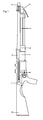
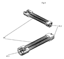
- FIG. 1 It is an overall description of the weapon where the parts are numbered 1 to 9. Said parts are described in the subsequent drawings with different numbering.
- FIG. 2 a receiver 10 is fixed to the barrel 3 by the in-between connection steel part 11, which is screwed 12 to the receiver 10.
- the tube 17 goes through the receiver lengthwise.
- the bolt 14 runs through the tube together with its inner parts: inertial mass 15, nut 16, the small balls 18 and the firing pin 19. Behind this bolt assembly 14 and aligned to it, are the spring 20, the follower 21 and the running top 20.1.
- FIG. 3 illustrates how the cylinder rotates automatically when the gun is fired.
- the bolt 14 moves backwards pushed by the shell.
- a groove 14.1 is in the bolt 14 and it moves backwards as well.
- the operating driving arm 23 rotates on the axle 23.3.
- the two - axle pivot lever 24 pushes the cylinder stop 31 and sends it to one of the cavities the cylinder 30 has for that purpose.
- the operating driving arm 23 returns to its original position by means of the spring 32.
- the cylinder stop 31 is sent back to its initial position by its spring 33 and disengages the cylinder 30.
- the bolt 14 occupies the upper canal of the cylinder 30 and secures its position.
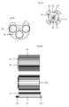
- FIG. 4A we have a rear view of the cylinder 30 and the small nuts 35 which are part of the steel star 34. We can see the holes where the cylinder stop 31 fits and the central hole where the axle 36 that keeps the cylinder 30 positioned fits. Inside said hole there is a tube 37 which centers the cylinder 30 on the axle 36 and acts as a tighten separator while the cylinder is fit into the gun.
- FIG. 4B there is a longitudinal sectional view of the cylinder 30. It shows how the axle 36 is fixed to the receiver 10 by means of a threaded end 36.1. The other end forms an "allen" nut with a cylindrical crown end 36.2. This axle 36 is firmly attached to the plate 40, which is embedded in the receiver 10.
- the separator 37 prevents the axle 36 from tightening the cylinder.
- the separator 37 has a cone shaped end to allow the bushing 39 of the cylinder 30 to slide with minimum friction.
- FIG. 4C we have a rear view of the bored plate 40 with the round openings 40.1 through which the cartridges in the tubes 45 move form the magazine 41 to the cylinder 30.
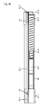
- the magazine 41 comprised three identical tubes 45 located as seen in the diagram in FIG 5A. They are a joint assembly by virtue of the fitting end 41.1 at the rear end, and fitting end 41.2 at the front end. The three tubes are open in their rear ends and closed in their front ends. There is a spiral spring 41.3 and a follower 41.4 in each one of them.
- the rod 42 that is part of the magazine assembly goes through the central axis of both fitting ends 41.1 and 41.2.
- the spring 44 At the front end 42.2 is the spring 44 which keeps the rod tensed forwards.
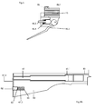
- the fixing device 46 comprises a main part 46.1 fastened to the barrel by the screws, and comprises a bolt 46.2 connected to a lever with cam 46.3 by means of the spring 46.4.
- the lever 46.3 turns towards the barrel 13
- the bolt 46.2 is pushed through the axle of the fitting 41.2 and pushes the rod 42 towards the receiver 10.
- the rear end 42.1 of the rod projects backwards and engages the cylindrical crown 36.2.
- the magazine 41 is firmly fixed to the gun.
- FIG. 7 we can see a longitudinal section of the firing mechanism 50 with the sure device off (Position A) and on (Position B); with the box 51, the trigger 52, the transferring bar 53, the hammer 54, the sear 55, the main spring 56, the sear spring 55.1, the axle 57 of the box 51, the axle 54.1 of the hammer 54, and the axle 55.2 of the sear 55.
- the system is assembled as follows: as the bolt 14 moves backwards, it pulls the point 54.2 of the hammer 54, and makes it turn around its axle 54.1 until - with the groove 54.3 - it mounts the sear 55.
- the spring 55.1 of the sear 55 keeps it in cocking position.
- the main spring 56 remains tense and pushes the bar 54.4.
- the transferring bar 53 recoils and pulls the sear 55 tail 55.3. It disengages from the groove 54.3 of the hammer 54, and the gun is fired.
- the disengagement of the sear 55 which is necessary for the gun to be cocked again while the shooter pulls the trigger, occurs when the hammer 54 is mounted. This is because the transferring bar 53 is pressed down by the projection 53.1 of the hammer 54, thus pulling it down and releasing it from the tail 55.3.
- the spring 59 pull the trigger and its transferring bar back to position.
- the box 51 is detachable when disassembling the gun. In FIG. 7. the sure device, locking or safety mechanism is also shown.
- a safety lever 70 is eccentrically pivotable around an axle 70.1 in a first end. In the position A the safety mechanism disengaged. By pivoting the lever 70 with its free end 70.2 downwards, the first end presses down the transferring bar 53, which is disengaged from the tail 55.3. As the lever is pushed down, the first end is also getting contact with sear 55 and locking the sear 55 and the hammer 54 from being moved. Further, the free end 70.2 of the lever 70 is now located in the space where a finger is inserted to pull the trigger 52.
- the safety mechanism comprise not only the locking mechanism that prevent the sear 55 and the hammer 54 from being moved, but also a physical obstacle preventing a finger to reach the trigger 52.
- the firing mechanism or trigger assembly 50 is detachable as one unit when disassembling the gun.
- FIG. 8A shows a section of the butt 60 with the tube 61. Its front end is screwed, and its rear end is fixed to the butt plate 61.2. It also shows the lock 62 with holes 61.3 and its spring 63 and cup 65, which lodges the lock assembly 62.
- the butt 60 can be disconnected without using tools so that it occupies little room when carried, and in order to remove the bolt assembly 14 (also denoted as 2) as well.
- the tube 61 is firmly attached to the butt plate 61.2.
- the butt plate is kept into position by the lock 62 which enters the hole and prevents it form rotating.
- the butt 60 is retained because it is tightened between the receiver 10 and the butt plate 61.2.
- the butt plate is kept into position by the lock 62, which enters the hole and prevents it from rotating.
- the butt 60 is retained because it is tightened between the receiver 10 and the butt plate 61.2.
- the recoil spring 20, together with the follower 21 can be removed from the rear side of the receiver 10. As a result, the bolt assembly 14 is released.
- the box 51 can be folded downwards around the axle 57 without using any tools, in order to check or do outdoor cleaning. It is only necessary to turn the wheel 59.2 of the rod 59, which is screwed 59.1 to the receiver 10.
- the magazine 41 is shown having three tubes 45.
- the magazine 41 also includes a fitting end 41.1 at the rear end of the magazine 41, and a fitting end 41.2 at the front end of the magazine 41. Between the fitting end 41.1 and the fitting end 41.2, and through the fittings the tubes 45 extend.
- FIG. 10 a detailed projected view of the cylinder 30, plate 40, and magazine assembly 41 is shown.
Landscapes
- Engineering & Computer Science (AREA)
- General Engineering & Computer Science (AREA)
- Toys (AREA)
Priority Applications (2)
| Application Number | Priority Date | Filing Date | Title |
|---|---|---|---|
| EP06122647A EP1914501A1 (fr) | 2006-10-20 | 2006-10-20 | Arme semi-automatique |
| PCT/EP2007/061279 WO2008046928A1 (fr) | 2006-10-20 | 2007-10-22 | Arme semi-automatique |
Applications Claiming Priority (1)
| Application Number | Priority Date | Filing Date | Title |
|---|---|---|---|
| EP06122647A EP1914501A1 (fr) | 2006-10-20 | 2006-10-20 | Arme semi-automatique |
Publications (1)
| Publication Number | Publication Date |
|---|---|
| EP1914501A1 true EP1914501A1 (fr) | 2008-04-23 |
Family
ID=37890639
Family Applications (1)
| Application Number | Title | Priority Date | Filing Date |
|---|---|---|---|
| EP06122647A Withdrawn EP1914501A1 (fr) | 2006-10-20 | 2006-10-20 | Arme semi-automatique |
Country Status (2)
| Country | Link |
|---|---|
| EP (1) | EP1914501A1 (fr) |
| WO (1) | WO2008046928A1 (fr) |
Cited By (1)
| Publication number | Priority date | Publication date | Assignee | Title |
|---|---|---|---|---|
| US9400148B2 (en) | 2013-09-27 | 2016-07-26 | Strum, Ruger & Company, Inc. | Removable shotgun magazine |
Citations (8)
| Publication number | Priority date | Publication date | Assignee | Title |
|---|---|---|---|---|
| US575265A (en) * | 1897-01-12 | Samuel ist | ||
| US580679A (en) * | 1897-04-13 | Magazine-gun | ||
| US4207797A (en) * | 1979-05-22 | 1980-06-17 | Gyorik Joseph J | Magazine for an automatic weapon |
| US4644930A (en) * | 1984-07-18 | 1987-02-24 | Robert Mainhardt | Gun for firing a variety of projectiles |
| US4709617A (en) * | 1984-06-21 | 1987-12-01 | Anderson John A | Firearm |
| US5119575A (en) * | 1990-10-22 | 1992-06-09 | Gajdica Michael S | Rotary magazine for firearms |
| WO2003078915A1 (fr) * | 2002-03-14 | 2003-09-25 | Snake River Machine, Inc. | Systeme et procede pour ameliorer la capacite du barillet d'une arme a feu |
| US20060101692A1 (en) * | 2004-11-16 | 2006-05-18 | Patrick Falenwolfe | Firearm operating mechanism and cartridge cylinder assembly |
-
2006
- 2006-10-20 EP EP06122647A patent/EP1914501A1/fr not_active Withdrawn
-
2007
- 2007-10-22 WO PCT/EP2007/061279 patent/WO2008046928A1/fr not_active Ceased
Patent Citations (8)
| Publication number | Priority date | Publication date | Assignee | Title |
|---|---|---|---|---|
| US575265A (en) * | 1897-01-12 | Samuel ist | ||
| US580679A (en) * | 1897-04-13 | Magazine-gun | ||
| US4207797A (en) * | 1979-05-22 | 1980-06-17 | Gyorik Joseph J | Magazine for an automatic weapon |
| US4709617A (en) * | 1984-06-21 | 1987-12-01 | Anderson John A | Firearm |
| US4644930A (en) * | 1984-07-18 | 1987-02-24 | Robert Mainhardt | Gun for firing a variety of projectiles |
| US5119575A (en) * | 1990-10-22 | 1992-06-09 | Gajdica Michael S | Rotary magazine for firearms |
| WO2003078915A1 (fr) * | 2002-03-14 | 2003-09-25 | Snake River Machine, Inc. | Systeme et procede pour ameliorer la capacite du barillet d'une arme a feu |
| US20060101692A1 (en) * | 2004-11-16 | 2006-05-18 | Patrick Falenwolfe | Firearm operating mechanism and cartridge cylinder assembly |
Cited By (1)
| Publication number | Priority date | Publication date | Assignee | Title |
|---|---|---|---|---|
| US9400148B2 (en) | 2013-09-27 | 2016-07-26 | Strum, Ruger & Company, Inc. | Removable shotgun magazine |
Also Published As
| Publication number | Publication date |
|---|---|
| WO2008046928A1 (fr) | 2008-04-24 |
Similar Documents
| Publication | Publication Date | Title |
|---|---|---|
| US9513074B1 (en) | Firearm with interchangeable parts | |
| US7562614B2 (en) | Closed bolt system with trigger assembly for converting a fully automatic submachine gun into a semi-automatic carbine | |
| US9310160B1 (en) | Hybrid metal/polymer pistol frame | |
| US7752795B1 (en) | Semi-automatic weapon for several tubes cartridges loading system for long guns | |
| US7444775B1 (en) | Caliber convertible AR-15 upper receiver system | |
| US7302881B1 (en) | Conversion kit and method for a ruger 10/22 semi-automatic .22 caliber rim fire rifle to shoot .17 mach 2 cartridges | |
| CN101458051B (zh) | 模块化便携式武器 | |
| US8176668B2 (en) | Recoil reducer for use with a firearm | |
| US5900577A (en) | Modular, multi-caliber weapon system | |
| US4505182A (en) | Firearm trigger mechanism | |
| US5149898A (en) | Fire control assembly | |
| US7735409B1 (en) | Conversion kit and method for a RUGER® 10/22® semi-automatic .22 caliber rim fire gun to shoot .17 mach 2 cartridges | |
| US4416186A (en) | Sear buffer | |
| US4475437A (en) | Sear actuator | |
| US4502367A (en) | Firearms bolt carrier assembly | |
| US4220071A (en) | Conversion kit for semi-automatic carbines | |
| US10788276B2 (en) | Rifle to fire pistol cartridges | |
| US5736667A (en) | Automatic firearm arranged for high safety and rapid dismantling | |
| US20170219305A1 (en) | Hybrid polymer lower receivers for firearms and metal threaded inserts, kits and methods therefor | |
| US9733034B1 (en) | Trigger assembly improved | |
| US10180296B2 (en) | Firearm adapted to use linked ammunition and kit for converting magazine-fed firearm to same | |
| US4999939A (en) | Breech load pistol and conversion | |
| US4914845A (en) | Breech load pistol and conversion | |
| US4649800A (en) | Self-contained blowback-type firing unit | |
| US4936035A (en) | Breech load pistol and conversion |
Legal Events
| Date | Code | Title | Description |
|---|---|---|---|
| PUAI | Public reference made under article 153(3) epc to a published international application that has entered the european phase |
Free format text: ORIGINAL CODE: 0009012 |
|
| AK | Designated contracting states |
Kind code of ref document: A1 Designated state(s): AT BE BG CH CY CZ DE DK EE ES FI FR GB GR HU IE IS IT LI LT LU LV MC NL PL PT RO SE SI SK TR |
|
| AX | Request for extension of the european patent |
Extension state: AL BA HR MK RS |
|
| 17P | Request for examination filed |
Effective date: 20081023 |
|
| AKX | Designation fees paid |
Designated state(s): AT BE BG CH CY CZ DE DK EE ES FI FR GB GR HU IE IS IT LI LT LU LV MC NL PL PT RO SE SI SK TR |
|
| 17Q | First examination report despatched |
Effective date: 20090615 |
|
| 17Q | First examination report despatched |
Effective date: 20110401 |
|
| STAA | Information on the status of an ep patent application or granted ep patent |
Free format text: STATUS: THE APPLICATION IS DEEMED TO BE WITHDRAWN |
|
| 18D | Application deemed to be withdrawn |
Effective date: 20111012 |