EP1914533A2 - Appareil et procédés pour la manipulation d'échantillons et l'analyse rhéologique - Google Patents
Appareil et procédés pour la manipulation d'échantillons et l'analyse rhéologique Download PDFInfo
- Publication number
- EP1914533A2 EP1914533A2 EP07075592A EP07075592A EP1914533A2 EP 1914533 A2 EP1914533 A2 EP 1914533A2 EP 07075592 A EP07075592 A EP 07075592A EP 07075592 A EP07075592 A EP 07075592A EP 1914533 A2 EP1914533 A2 EP 1914533A2
- Authority
- EP
- European Patent Office
- Prior art keywords
- sample
- primary
- chamber
- containment vessel
- primary chamber
- Prior art date
- Legal status (The legal status is an assumption and is not a legal conclusion. Google has not performed a legal analysis and makes no representation as to the accuracy of the status listed.)
- Withdrawn
Links
Images



Classifications
-
- G—PHYSICS
- G01—MEASURING; TESTING
- G01N—INVESTIGATING OR ANALYSING MATERIALS BY DETERMINING THEIR CHEMICAL OR PHYSICAL PROPERTIES
- G01N1/00—Sampling; Preparing specimens for investigation
- G01N1/02—Devices for withdrawing samples
-
- B—PERFORMING OPERATIONS; TRANSPORTING
- B01—PHYSICAL OR CHEMICAL PROCESSES OR APPARATUS IN GENERAL
- B01L—CHEMICAL OR PHYSICAL LABORATORY APPARATUS FOR GENERAL USE
- B01L3/00—Containers or dishes for laboratory use, e.g. laboratory glassware; Droppers
- B01L3/50—Containers for the purpose of retaining a material to be analysed, e.g. test tubes
- B01L3/502—Containers for the purpose of retaining a material to be analysed, e.g. test tubes with fluid transport, e.g. in multi-compartment structures
-
- G—PHYSICS
- G01—MEASURING; TESTING
- G01N—INVESTIGATING OR ANALYSING MATERIALS BY DETERMINING THEIR CHEMICAL OR PHYSICAL PROPERTIES
- G01N33/00—Investigating or analysing materials by specific methods not covered by groups G01N1/00 - G01N31/00
- G01N33/26—Oils; Viscous liquids; Paints; Inks
- G01N33/28—Oils, i.e. hydrocarbon liquids
- G01N33/2823—Raw oil, drilling fluid or polyphasic mixtures
-
- G—PHYSICS
- G02—OPTICS
- G02B—OPTICAL ELEMENTS, SYSTEMS OR APPARATUS
- G02B23/00—Telescopes, e.g. binoculars; Periscopes; Instruments for viewing the inside of hollow bodies; Viewfinders; Optical aiming or sighting devices
- G02B23/24—Instruments or systems for viewing the inside of hollow bodies, e.g. fibrescopes
- G02B23/2476—Non-optical details, e.g. housings, mountings, supports
- G02B23/2492—Arrangements for use in a hostile environment, e.g. a very hot, cold or radioactive environment
-
- B—PERFORMING OPERATIONS; TRANSPORTING
- B01—PHYSICAL OR CHEMICAL PROCESSES OR APPARATUS IN GENERAL
- B01L—CHEMICAL OR PHYSICAL LABORATORY APPARATUS FOR GENERAL USE
- B01L2300/00—Additional constructional details
- B01L2300/06—Auxiliary integrated devices, integrated components
- B01L2300/0627—Sensor or part of a sensor is integrated
- B01L2300/0654—Lenses; Optical fibres
-
- B—PERFORMING OPERATIONS; TRANSPORTING
- B01—PHYSICAL OR CHEMICAL PROCESSES OR APPARATUS IN GENERAL
- B01L—CHEMICAL OR PHYSICAL LABORATORY APPARATUS FOR GENERAL USE
- B01L2300/00—Additional constructional details
- B01L2300/08—Geometry, shape and general structure
- B01L2300/0861—Configuration of multiple channels and/or chambers in a single devices
- B01L2300/0877—Flow chambers
-
- B—PERFORMING OPERATIONS; TRANSPORTING
- B01—PHYSICAL OR CHEMICAL PROCESSES OR APPARATUS IN GENERAL
- B01L—CHEMICAL OR PHYSICAL LABORATORY APPARATUS FOR GENERAL USE
- B01L2300/00—Additional constructional details
- B01L2300/14—Means for pressure control
-
- B—PERFORMING OPERATIONS; TRANSPORTING
- B01—PHYSICAL OR CHEMICAL PROCESSES OR APPARATUS IN GENERAL
- B01L—CHEMICAL OR PHYSICAL LABORATORY APPARATUS FOR GENERAL USE
- B01L7/00—Heating or cooling apparatus; Heat insulating devices
-
- G—PHYSICS
- G01—MEASURING; TESTING
- G01N—INVESTIGATING OR ANALYSING MATERIALS BY DETERMINING THEIR CHEMICAL OR PHYSICAL PROPERTIES
- G01N1/00—Sampling; Preparing specimens for investigation
- G01N1/02—Devices for withdrawing samples
- G01N1/04—Devices for withdrawing samples in the solid state, e.g. by cutting
- G01N1/08—Devices for withdrawing samples in the solid state, e.g. by cutting involving an extracting tool, e.g. core bit
-
- G—PHYSICS
- G01—MEASURING; TESTING
- G01N—INVESTIGATING OR ANALYSING MATERIALS BY DETERMINING THEIR CHEMICAL OR PHYSICAL PROPERTIES
- G01N1/00—Sampling; Preparing specimens for investigation
- G01N1/28—Preparing specimens for investigation including physical details of (bio-)chemical methods covered elsewhere, e.g. G01N33/50, C12Q
- G01N1/40—Concentrating samples
- G01N1/4077—Concentrating samples by other techniques involving separation of suspended solids
-
- G—PHYSICS
- G01—MEASURING; TESTING
- G01N—INVESTIGATING OR ANALYSING MATERIALS BY DETERMINING THEIR CHEMICAL OR PHYSICAL PROPERTIES
- G01N1/00—Sampling; Preparing specimens for investigation
- G01N1/02—Devices for withdrawing samples
- G01N1/10—Devices for withdrawing samples in the liquid or fluent state
- G01N2001/1006—Dispersed solids
- G01N2001/1012—Suspensions
- G01N2001/1025—Liquid suspensions; Slurries; Mud; Sludge
-
- G—PHYSICS
- G01—MEASURING; TESTING
- G01N—INVESTIGATING OR ANALYSING MATERIALS BY DETERMINING THEIR CHEMICAL OR PHYSICAL PROPERTIES
- G01N1/00—Sampling; Preparing specimens for investigation
- G01N1/02—Devices for withdrawing samples
- G01N1/10—Devices for withdrawing samples in the liquid or fluent state
- G01N2001/1031—Sampling from special places
- G01N2001/105—Sampling from special places from high-pressure reactors or lines
-
- G—PHYSICS
- G01—MEASURING; TESTING
- G01N—INVESTIGATING OR ANALYSING MATERIALS BY DETERMINING THEIR CHEMICAL OR PHYSICAL PROPERTIES
- G01N35/00—Automatic analysis not limited to methods or materials provided for in any single one of groups G01N1/00 - G01N33/00; Handling materials therefor
- G01N35/10—Devices for transferring samples or any liquids to, in, or from, the analysis apparatus, e.g. suction devices, injection devices
- G01N2035/1027—General features of the devices
- G01N2035/1034—Transferring microquantities of liquid
Definitions
- the present invention relates generally to the field of fluid sample handling and/or interfacial rheology measurement at temperature and pressure conditions existing at the source of the sample, or at least temperatures different than ambient, including, but not limited to, reservoir hydrocarbon and aqueous based fluids, drilling muds, frac fluids, and the like having multiple phases (solids and liquid).
- Reservoir fluids often contain suspended particles under pressure and temperature conditions similar to those experienced in petroleum reservoirs and petroleum production systems.
- the particles may be in the form of a second liquid phase (hydrocarbon or aqueous based droplets) or in the form of a solid (organic or inorganic).
- the presence of these particles is related to the phase behavior of the petroleum fluid and thus, the nature and/or composition of these particles may change with changes in pressure, temperature, or overall composition.
- phase behavior and physical properties of a reservoir fluid can be reasonably estimated through equation of state model(s) that have been tuned using experimental data.
- the fluid composition is normally described by lumped values (or pseudo components) that represent the average behavior of various portions within the fluid, such as C30+ compositions or SARA fractions.
- C30+ compositions acceptable average critical values are assigned to each pseudo component so that the collection of pseudo components can be used in simulation packages to calculate the phase behavior and properties of each phase. While providing simplification of the simulation and analysis, such averaging can result in the loss of small, yet important variations in chemical composition that can affect large-scale behaviors. Examples of such behavior that have been observed in recent literature and internal studies are described below.
- Asphaltene Precipitation and Deposition Asphaltenes are heavy, highly aromatic molecules that often precipitate from oils due to reductions in pressure and/or temperature or blending with incompatible fluids (see A. Hammami and J. Ratulowski in: Asphaltenes, Heavy Oils and Petroleomics, Oliver C. Mullins, Eric Y. Sheu, Ahmed Hammami, Alan Marshall, Editors, Kluwer Academic Publications, PRECIPITATION AND DEPOSITION OF ASPHALTENES IN PRODUCTION SYSTEMS: A FLOW ASSURANCE OVERVIEW, Chapter 23, 2006 ). Asphaltenes also contain multiple polar compounds; including oxygen, nitrogen, and sulphur that make the asphaltene molecules surface active.
- PVT pressure-volume-temperature
- a hydrocarbon-based fluid would be placed inside the PVT cell under pressure and temperature conditions similar to those experienced within a petroleum reservoir or in the petroleum production process. The pressure and/or temperature of the fluid would then be changed to induce the formation of a solid precipitate (e.g. asphaltene).
- Detection of solid formation in the hydrocarbon fluid may be done using near-infrared detectors, x-ray detection, or visual detection via a high pressure, high temperature microscopy method. These detection methods are limited to suspended particle detection only and cannot isolate or sample individual particles for subsequent analysis.
- high-temperature, high-pressure filtration may be used to collect the asphaltene aggregates and/or flocs. While commonly used, the high-pressure, high-temperature filtration process contains some potentially serious limitations to the analysis of asphaltene precipitate. The first and obvious limitation is that the floc size and amount of the recovered asphaltene depends on the pore size of the filter. Also, one must be very careful not to cause precipitated solids (wax and/or asphaltenes) to grate through the pores of the filter by creating too large of a pressure drop across the filter. Secondly, asphaltenes collected by filtration often contain trapped oil that contains dissolved organic solids (wax or asphaltene).
- any measurements completed on the filtered solids will only provide information about "average” asphaltene properties.
- the current protocols do not permit sampling and analysis of individual flocs and/or aggregates, an exercise that may reveal possible variations in chemical composition between the aggregates. With selective high-temperature, high-pressure micro-sampling, it may be possible to detect these compositional variations that contribute to both the surface activity and aggregation behavior of asphaltenes.
- a pressure source air is used to push the fluid through the membrane.
- this micro-filtration/sampling device could be used for any general micro-filtration, its intended use is for the filtration of blood samples. Again the device is not rated to the pressure and temperature range of interest in the micro-sampling of hydrocarbon reservoir fluids.
- United States Published Patent application no. 20040232075 A1 discloses a device and method to wash and concentrate (adjust composition of) solid particles from a suspension sample.
- a filter membrane is used to produce a permeate (fluid with no solids) flow low in solid particulates.
- a back-flushing mechanism was introduced to remove the solid particles from the membrane surface to recover filtration efficiency.
- the maximum allowable differential pressure across the membrane is 14.5 psi. As such the operating pressure was limited to atmospheric conditions. Maximum allowable fluid viscosity is 5 cP.
- a micro-sampling device for collecting a pressurized liquid or gas sample for injection into a chromatography apparatus was disclosed in U.S. Pat. No. 4,688,436 (Richon et al ).
- the device isolates a small volume of the reservoir fluid under the actual pressure and temperature before introducing it into a chromatograph carrier gas stream, thus carrying the total sample into the chromatograph. No measure of pressure and temperature ratings and sample volume is provided in the document.
- Micro-sampling has been extensively used in the medical, biological, and botanical sciences to collect specimen (micro-samples from living tissues and cells).
- One such instrument is the pressure probe described by Tomos et al., "The pressure probe: A versatile tool in plant cell physiology", Annual Review of Plant Physiology and Plant Molecular Biology, 50 (1999), 447-472 , which has evolved from an instrument for measuring cell turgor and other water relation parameters into a device for sampling the content of individual higher plant cells in situ in the living plant.
- the so-called pressure probe is not suited for the pressure and temperature range of interest for hydrocarbon phase behavior.
- a common technique utilizes glass micropipettes to capture and manipulate individual droplets or cells within an aqueous or hydrocarbon media at atmospheric pressure and near ambient temperature conditions (see for example Moran, "Micro-Mechanics of Emulsion Drops", PhD Thesis, University of Alberta, Edmonton, 2001 ).
- a schematic illustration is presented in FIG. 1. The technique involves placing a liquid containing suspend particles into a small glass container 16 open on two sides. Container 16 is then placed beneath a light source 2 such that individual particles may be observed, with the assistance of a microscope 4.
- one or more micropipettes 18, 20 are then inserted through the open sides of glass container 16 such that the tips of the micropipettes may be observed through microscope 4.
- Three-dimensional manipulators 6, 7 are then used to move the tips of the micropipettes and thus capture and manipulate suspended particles 22.
- a power source 8 powers light source 2, and may power a VCR 10 (which may record the images) and a monitor 12.
- Glass micro-pipettes has also been used to investigate the interfacial rheology of liquid droplets (see for example Moran et al., "Shape relaxation of an elongated viscous drop", Journal of Colloid and Interface Science, 267 (2003), 483-493 ).
- the strength and breakup of flocs have been studied ( Yeung A.K.C and Pelton R., “Micromechanics: A New Approach to Studying the Strength and Breakup of Flocs", Journal of Colloids and Interface Science, 184 (1996), 579-585 ).
- apparatus and methods for isolating and/or measuring interfacial rheological properties of a portion of a sample from a primary sample, under temperature and pressure conditions representative of the source of the primary sample (or at least different from ambient conditions), are described.
- the temperature and pressure conditions of the primary sample may be those of a petroleum reservoir or other hydrocarbon-bearing geologic formation, but the invention is not so limited.
- the primary sample may comprise any sample at elevated temperatures and pressures, including, but not limited to compositions comprising hydrocarbons (including sour hydrocarbons which may include hydrogen sulfide, mercaptans, and other sulfur-containing compounds), water, organic and/or inorganic solids, and may include micelles, macromolecules, globules, resins, asphaltenes, hydrocarbon and aqueous based fluids, drilling muds, frac fluids, and the like having multiple phases (solids and liquid).
- the primary sample composition may comprise one or more of each phase. Stated differently, a primary sample composition may comprise one or more liquid phases, one or more solid phases, and one or more gaseous phases.
- apparatus comprising:
- Apparatuses within this aspect of the invention include those wherein the sample probe is selected from solid and hollow objects, and may be selected from a pointed object, a cup-shaped object, a catheter-like device comprising a sample grabber, and a pipette (for example a glass micropipette).
- the primary sample containment vessel may comprise at least one viewing port, wherein the viewing port may comprise any natural or synthetic material having suitable optical properties (substantially transparent) and mechanical properties able to withstand the desired temperature and pressure conditions. Suitable materials include sapphire and quartz. Certain embodiments of apparatus of the invention may have two or more viewing ports; one of the viewing ports may allow a camera or other charge coupled device to visually access the primary chamber. Another viewing port may allow light from a light source to enter the primary chamber. In certain embodiments the viewing port or ports allow complete viewing of the distal end of the sample probe (and thus the secondary sample) from the moment the secondary sample is collected by the sample probe, through movement of the distal tip toward the sample container, through the time the secondary sample is placed into the collection chamber.
- Apparatuses within this aspect of the invention include those wherein the fluid connection between the primary sample chamber and secondary sample collection chamber is selected from mechanical barriers, interfacial barriers and any other form of barrier that would prevent the secondary sample collection chamber being contaminated by the non-sampled material in the primary sample chamber.
- a mechanical barrier may be an elastomeric membrane
- an example of an interfacial barrier may be an interface between two immiscible fluids.
- the secondary sample collection container includes a floating piston which functions to allow secondary samples and a solvent to fill a sub-chamber of the sample collection container, between the piston and the elastomeric membrane.
- the floating piston may be fluidly connected to a system allowing two-way flow of a motive fluid to effect and/or allow movement of the floating piston.
- the motive fluid may be gas or liquid.
- the seal between the sample probe and the primary containment vessel comprises a joint, for example a ball joint, having a substantially central passage therethrough, wherein the sample probe is positioned in the central passage.
- the joint may be an integral component of a pressurized sample probe container defining a sample probe chamber.
- the joint may allow the distal end of the sample probe to be moved in 3-dimensional space, including in translational movements (x, y, z) or by cylindrical movements (circular, radial and translational) or equivalent, inside of the primary chamber, and translational movement of the sample probe in and out of the secondary sample collection and sample probe chambers.
- the movement of the sample probe may be performed manually or automatically, for example, through computer control.
- the sample probe chamber may be fluidly connected to a system allowing two-way flow of a solvent to effect pressurization of the sample probe chamber to a pressure substantially equal to that of the primary containment vessel.
- the distal end of the sample probe is able to isolate secondary samples having a largest length dimension ranging from about 1 to about 100 micrometers, and in other embodiments of no larger than about 1 millimeter.
- inventive apparatus may be constructed in any manner that allows the sample probe to function to collect a secondary sample and move the secondary sample into the secondary sample collection container. Apparatus of this aspect of the invention may be used to capture and store micrometer-sized samples of solid particles or liquid droplets from petroleum fluids under high pressure and high temperature conditions, although apparatus within this aspect of the invention are not so limited.
- apparatus for measuring interfacial rheology of particles in a primary sample at non-ambient conditions comprising:
- Apparatuses within this aspect of the invention share many, but not all, of the features of apparatus within the first aspect of the invention.
- the sample probes may or may not be positioned so that the distal ends are opposed, and each may comprise a glass micropipette as described in relation to the first aspect of the invention.
- Apparatus within the second aspect of the invention may find use for measuring values related to interfacial surface rheology (e.g., interfacial tension, interfacial viscosity, interfacial elasticity, and like interfacial properties), and/or rupture strength for solid flocs (aggregates).
- interfacial surface rheology e.g., interfacial tension, interfacial viscosity, interfacial elasticity, and like interfacial properties
- a method of obtaining a secondary sample from a primary sample comprising:
- Methods within this aspect of the invention include those wherein the isolating and transferring steps comprise manipulating the one or more sample probes fluidly connected to the primary containment vessel through a joint, such as described in relation to the first aspect of the invention, such as a ball joint, allowing the sample probe to be moved in 3-dimensional space, including in translational movements (x, y, z) or by cylindrical movements (circular, radial and translational) or equivalent, inside of the primary chamber.
- a joint such as described in relation to the first aspect of the invention, such as a ball joint
- a method of manipulating one or more particles in a primary sample at non-ambient conditions comprising:
- Interfacial rheological parameters may include, but are not limited to, interfacial tension, interfacial viscosity, interfacial elasticity, rupture strength for solid flocs (aggregates), and the like.
- Manipulation of the one or more particles may be performed using two opposed micropipettes, although the invention is not so limited.
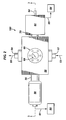
- FIGS. 2 and 3 illustrate schematic plan and cross-sectional views, respectively, of one apparatus embodiment 100 within the invention. It will be recognized by those skilled in the art that not all or the features in embodiment 100 may be necessary in all embodiments.
- Embodiment 100 comprises a primary sample containment vessel 50. Containment vessel 50 includes a primary sample inlet 52 and outlet 54, where a primary sample may enter and exit containment vessel 50, as illustrated by flow arrows 53 and 55.
- Containment vessel 50 comprises, in this embodiment, essentially a hollow metal block containing a top sapphire, quartz or other suitable material window 68 secured using a flange 66, a bottom window 69 also secured by a flange (not illustrated), and a more or less centrally located primary chamber 51, more easily viewed in FIG. 3.
- the primary sample inlet 52 and outlet 54 are illustrated connected perpendicular to the sapphire windows, but this is not strictly necessary to the invention.
- Primary sample inlet 52 and outlet 54 are used to isobarically and isothermally flow the reservoir fluid primary sample composition into primary chamber 51.
- a secondary sample collection vessel 58 is fluidly connected to containment vessel 50 through a port 56.
- a hydraulic pump 60 and line 61 supply and accept a hydraulic or other fluid to a sub-chamber internal of secondary sample collection vessel 58.
- a ball joint 70 fluidly connects containment vessel 50 with a micropipette sample vessel 62 in this embodiment.
- a manipulating handle is illustrated at 64 for manipulating a micropipette 65.
- a solvent pump 84 and line 85 are fluidly connected to micropipette sample vessel 62, whose operation in this embodiment will become apparent during the discussion of FIG. 3.
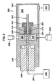
- FIG. 3 is a cross-sectional view along the line 3-3 of embodiment 100 of FIG. 2, note that light from a light source 9 may be passed through bottom window 69, allowing the primary sample composition inside primary chamber 51 to be illuminated.
- Light source 9 may emit white light, laser light, polarized light or light of any single or combination of wavelengths.
- a color CCD camera 8 equipped with a high magnification lens may be positioned above top window 68 to allow for microscopic images of the fluid in primary chamber 51 to be captured in real-time.
- An opening through joint 70 allows micropipette 65 to access the primary sample composition within primary sample chamber 51.
- Micropipette 65 is sealed in a through passage of ball joint 70 by seals 74 and 76, but micropipette 65 is able to slide or otherwise move through seals 74 and 76.
- Port 56 provides an opening and serves as a fluid passage to a sub-chamber 94' in secondary sample collection vessel 58, where secondary samples (for example, particles) isolated from the primary sample are stored, along with a solvent in this embodiment. All of the openings in and out of containment vessel 50 comprise appropriate seals to ensure that the primary sample composition, same as a reservoir fluid, can be safely maintained under high-pressure, high-temperature conditions within primary sample chamber 51. Pressure inside primary sample chamber 51 is controlled using high-pressure positive displacement pumps (not illustrated) connected to the various flow lines, for example primary sample inlet 52 and outlet 54 (FIG. 2).
- the sample probe is a micropipette sampling tool 65, although other sample probes may be useful in practicing the invention, as further discussed herein.
- a micropipette sample probe When a micropipette sample probe is used, it comprises a hollow tube open on both ends, where one end, referred to herein as the distal end 96, may be tapered to a tip diameter on the order of tens of micrometers.
- tapered distal end 96 is located in primary chamber 51 with the tapered distal end 96 located in the space between sapphire windows 68 and 69 so that it can be viewed on the CCD camera.
- micropipette 65 extends through the center of joint 70, which is also sealed as illustrated at 72, and into a pressure chamber 94 defined by micropipette sample vessel 62.
- Micropipette 65 may be formed from a single piece of metal, plastic, or glass, or may be formed from a composite of materials, such as a glass tube encased in metal or two metal tubes in a pipe-in-pipe configuration.
- Dynamic seals 74 and 76 surrounding the micropipette in joint 70 act to (i) isolate chamber 94 from primary chamber 51, and (ii) allow limited 3-dimensional movement of micropipette 65, as indicated by double-headed arrows 78, 80.
- Micropipette sample vessel 62 may be formed from a single piece of metal, including joint 70, which may be a ball joint.
- the ball joint design allows movement of micropipette tip 96 in 3-dimensions as indicated by double-headed arrow 80, where the center of the ball joint acts as the pivot point for radial and circular movement.
- the radial and circular movements allow micropipette distal end 96 to cover a cone shaped space 83, as illustrated schematically in FIG. 4.
- the combined translational 78, radial 79, and circular 81 movements allow for complete three-dimensional movement of at least the micropipette distal end 96 within primary chamber 51.
- Computer operated hydraulic or step gear motors may be used to control the movement of micropipette distal end 96.
- a fitting 82 provides a connection between a solvent pump 84, a solvent supply line 85, and sample vessel 62.
- the ball mounted micropipette chamber 94 may be filled with a carefully selected solvent during operation and the pressure of ball mounted micropipette chamber 94 is balanced with the pressure in primary chamber 51.
- Solvents useful in the invention may be selected from water, organic chemicals, and mixtures thereof, and may include inorganic ingredients.
- the composition is highly dependent on the particular pressure, temperature, and secondary sample to be isolated.
- reservoir fluids often contain suspended particles under pressure and temperature conditions similar to those experienced in petroleum reservoirs and petroleum production systems.
- the particles may be in the form of a second liquid phase (hydrocarbon or aqueous based) or in the form of a solid (organic or inorganic).
- the presence of these particles is related to the phase behavior of the petroleum fluid and thus, the nature and/or composition of these particles may change with changes in pressure, temperature, or overall composition.
- the solvent is selected based on these principles.
- Sample collection vessel 58 may be a vessel that is relatively small in volume compared with primary containment vessel 50, and is generally manufactured using the same or similar high-temperature, high-pressure corrosion resistant materials as containment vessel 50.
- Sample collection vessel 58 may be shaped as a cylinder, although this is not a requirement.
- An internal floating piston 90 acts to isolate a sub-chamber 92 filled with hydraulic fluid supplied from a positive displacement pump 60 and line 61, and a second sub-chamber 94' filled with the same solvent that is in sample vessel 62 (i.e. the same solvent used in pipette sample chamber 94).
- Sub-chamber 94' and the solvent therein are separated from primary sample composition in primary sample chamber 51 by a rubber membrane or fluid interface or interface of any kind or plug 86.
- the pressure of solvent in sub-chamber 94' is substantially balanced with that of the pressure in primary sample chamber 51.
- the entire apparatus may be temperature controlled.
- Sources of temperature control include liquid baths, liquid jackets, peltier devices, convection gas baths, and the like.
- a convection air bath may be employed to control the temperature in the entire apparatus to within ⁇ 5°C, and in certain embodiments within ⁇ 0.5°C. If vibration is to be minimized, apparatus of the invention may be isolated from its surrounding to minimize vibration of the apparatus.
- primary sample chamber 51 will contain a fluid that is subjected to pressure and temperature conditions where either solid particles (e.g. wax or asphaltene) or droplets of a second liquid phase will be formed.
- An operator will be able to directly observe such micrometer-sized particles as well as the tip 96 of micropipette 65.
- the tip 96 of micropipette 65 will then be moved adjacent to a target particle and a slight relative suction draws the particle just inside tip 96, as illustrated in FIG. 3.
- the particle will be placed inside sub-chamber 94' of sample collection vessel 58 by pushing tip 96 of micropipette 65 through a barrier such as an elastomeric membrane 86, or liquid interface between two immiscible liquids. With tip 96 inside sub-chamber 94', the particle is then displaced from micropipette 65. Multiple particle samples can be obtained by removing tip 96 from sub-chamber 94', positioning tip 96 adjacent to the next target particle, and repeating the capture/storage process. Once the sampling is complete, sample collection vessel 58 is isolated and removed from the apparatus and the sample collected for subsequent analytical characterization.
- a barrier such as an elastomeric membrane 86, or liquid interface between two immiscible liquids.
- the minimum size or amount of secondary sample collected is determined by the minimum sample requirement for the specific analytical method of choice. Some of the currently available compositional analysis techniques only require nano-grams of material for proper analysis. Depending on the size of collected solid particles and/or liquid droplets and their density, multiple secondary sample collections may be required to collect enough material for analysis. For these and other reasons, secondary sample collection using apparatus and methods of the invention may be automated.
- Primary sample compositions from which secondary samples may be collected may be gaseous, liquid, supercritical, and any combination thereof.
- the primary sample may comprise any sample at elevated temperatures and pressures, including, but not limited to compositions comprising hydrocarbons (including sour hydrocarbons which may include hydrogen sulfide, mercaptans, and other sulfur-containing compounds), water, organic and/or inorganic solids, and may include micelles, macromolecules, globules, resins, asphaltenes, hydrocarbon and aqueous based fluids, drilling muds, frac fluids, and the like having multiple phases (solids and liquid).
- the primary sample composition may comprise one or more of each phase.
- the term "reservoir" may include hydrocarbon deposits accessible by one or more wellbores.
- a “wellbore” includes cased, cased and cemented, or open-hole wellbores, and may be any type of well, including, but not limited to, a producing well, a non-producing well, an experimental well, an exploratory well, and the like.
- Wellbores may be vertical, horizontal, any angle between vertical and horizontal, diverted or non-diverted, and combinations thereof, for example a vertical well with a non-vertical component.
- high temperature, high pressure means any temperature and pressure conditions that are above atmospheric pressure and above 20°C.
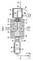
- FIG. 5 is a schematic cross-sectional view of another apparatus embodiment 200 within the invention, suitable for isolating secondary samples from a primary sample.
- Embodiment 200 includes a body 250 forming a primary sample chamber 251 (inlet and outlet are similar to those of embodiment 100 discussed above and are not illustrated) along with sapphire windows 268 and 269.
- a sample isolated by distal end 286 of sample probe 265 is viewable by a microscope 208 (with the help of light source 209) the entire time it is present in primary sample chamber 251 until deposited in secondary sample chamber 294' of secondary sample container 258.
- a line 261 connects chamber 294' to a hydraulic pump 260.
- a hydraulic chamber 294 formed inside a sample probe containment vessel 262 is also connected to a hydraulic pump 284.
- Apparatus embodiment 200 differs from apparatus embodiment 100 in the operation of sample probe 265.
- sample probe 265 is supported in an adjustment block 261, which has a central passage through which the sample probe is inserted into and retracted from primary sample chamber 251 for the purpose of isolating secondary samples.
- Seals 272 and 276 prevent hydraulic fluid in chamber 294 from entering primary sample chamber 251 and vice versa, and allows sample probe 265, and thus distal end 286, to move in translational X-Y-Z directions, as indicated by the coordinate reference arrows.
- FIGS. 6 and 7 are schematic cross-sections of apparatus embodiments 600 and 700, respectively, of the invention that may be used to study rheological properties of particles and flocs.
- embodiment 600 includes a primary sample containment vessel 650, the internal surfaces of which in part define a primary sample chamber 651.
- Sapphire windows 668 and 669 also in part define primary sample chamber 651.
- Embodiment 600 further comprises a first ball joint 670 fluidly connecting containment vessel 650 with a first micropipette sample vessel 662 in this embodiment.
- a first manipulating handle is illustrated at 664 for manipulating a first micropipette 665.
- a solvent pump 684 and line 685 are fluidly connected to first micropipette sample vessel 662, whose operation in this embodiment is essentially the same as described above with respect to embodiment 100 illustrated in FIG. 3.
- Light from a light source 609 may be passed through bottom window 669, allowing the primary sample composition inside primary chamber 651 to be illuminated.
- Light source 609 may emit white light, laser light, polarized light or light of any single or combination of wavelengths.
- a color CCD camera 608 equipped with a high magnification lens may be positioned above top window 668 to allow for microscopic images of the fluid and isolated particles in primary chamber 651 to be captured in real-time.
- An opening through first ball joint 670 allows first micropipette 665 to access the primary sample composition within primary sample chamber 651.
- First micropipette 665 is sealed in a through passage of first ball joint 670 by seals 674 and 676, but first micropipette 665 is able to slide or otherwise move through seals 674 and 676.
- embodiment 600 further comprises a second ball joint 671 fluidly connecting containment vessel 650 with a second micropipette sample vessel 663 in this embodiment.
- a second manipulating handle is illustrated at 664' for manipulating a second micropipette 667.
- a solvent pump 684' and line 685' are fluidly connected to second micropipette sample vessel 663, whose operation in this embodiment is essentially the same as described above with respect to first micropipette 665.
- Second micropipette 667 is sealed in a through passage of second ball joint 671 by seals 675 and 677, but second micropipette 667 is able to slide or otherwise move through seals 675 and 677. All of the openings in and out of containment vessel 650 comprise appropriate seals to ensure that the primary sample composition can be safely maintained under high-pressure, high-temperature conditions within primary sample chamber 651. Pressure inside primary sample chamber 651 is controlled using high-pressure positive displacement pumps (not illustrated) connected to the various flow lines, for example primary sample inlet and outlet (not illustrated in FIG. 6 but essentially the same as embodiment 100 in FIG. 2).
- the sample probes are micropipette sampling tools 665 and 667, although other sample probes may be useful in practicing the invention, as further discussed herein.
- micropipette sample probes When micropipette sample probes are used, they comprise a hollow tube open on both ends, where one end, referred to herein as distal ends 696 and 696', may be tapered to a tip diameter on the order of tens of micrometers.
- tapered distal ends 696 and 696' are located in primary chamber 651 with the tapered distal ends 696, 696' located in the space between sapphire windows 668 and 669 so that they may be viewed on the CCD camera 608.
- micropipettes 665, 667 extend through the center of joints 670, 671 which are also sealed as illustrated at 672, 673 and into respective pressure chambers 694, 695 defined by micropipette sample vessels 662, 663.
- Micropipettes 665, 667 may be formed from a single piece of metal, plastic, or glass, or may be formed from a composite of materials, such as a glass tube encased in metal or two metal tubes in a pipe-in-pipe configuration.
- Dynamic seals 674, 675, 676, and 677 surrounding micropipettes in joints 670, 671 act as explained previously with respect to embodiment 100 to isolate chamber primary chamber 651, and allow limited 3-dimensional movement of micropipettes 665, 667 as indicated by double-headed arrows 678, 679, 680, and 681.
- Micropipette sample vessels 662, 663 may be formed from a single piece of metal, including joints 670, 671 which may be ball joints, but need not be.
- the ball joint design allows movement of micropipette tips 696, 696' in 3-dimensions, where the center of the ball joint acts as the pivot point for radial and circular movement.
- the radial and circular movements allow micropipette distal ends 696, 696' to cover cone shaped spaces 83, as illustrated schematically in FIG. 4.
- the combined translational, radial, and circular movements allow for complete three-dimensional movement of at least the micropipette distal ends 696, 696' within primary chamber 651, and thus particles samples.
- Computer operated hydraulic or step gear motors may be used to control the movements of micropipette distal ends 696, 696'.
- Fittings 682, 682' provide connections between solvent pumps 684, 684', and solvent supply lines 685, 685'.
- the ball mounted micropipette chambers 694, 695 may be filled with a carefully selected solvent during operation and the pressure of ball mounted micropipette chambers 694, 695 are balanced with the pressure in primary chamber 651.
- FIG. 7 is a schematic cross section of another apparatus embodiment 700 of the invention that may be used to study rheological properties of particles and flocs.
- Embodiment 700 includes a body 750 forming a primary sample chamber 751 (inlet and outlet are similar to those of embodiment 100 discussed above and are not illustrated) along with sapphire windows 768 and 769.
- a sample isolated by distal end 796 of a first sample probe 765 is viewable by a microscope 708 (with the help of light source 709) the entire time it is present in primary sample chamber 751.
- a first hydraulic chamber 794 formed inside a first sample probe containment vessel 762 is connected to a first hydraulic pump 784.
- a distal end 796' of a second sample probe 767 is viewable by microscope 708 (with the help of light source 709) the entire time it is present in primary sample chamber 751.
- a second hydraulic chamber 795 formed inside second sample probe containment vessel 763 is connected to a second hydraulic pump 785.
- Apparatus embodiment 700 differs from apparatus embodiment 600 in the operation of sample probes 765, 767.
- sample probes 765, 767 are supported in respective adjustment blocks 761, 759 each of which have a central passage through which the sample probe is inserted into and retracted from primary sample chamber 751 for the purpose of manipulating particles in primary sample chamber 751.
- Seals 772, 773, 776 and 777 prevent hydraulic fluid in chambers 794, 795 from entering primary sample chamber 751 and vice versa, and allow sample probes 765, 767, and thus distal ends 796, 796' to move in translational X-Y-Z directions, as indicated by the coordinate reference arrows.
- Embodiments 200, 600, and 700 may include provisions for temperature control as explained in reference to embodiment 100.
- a power source powers the light source, and may power a VCR and monitor or other viewing device.
Landscapes
- Chemical & Material Sciences (AREA)
- Physics & Mathematics (AREA)
- Health & Medical Sciences (AREA)
- General Health & Medical Sciences (AREA)
- Analytical Chemistry (AREA)
- General Physics & Mathematics (AREA)
- Life Sciences & Earth Sciences (AREA)
- Engineering & Computer Science (AREA)
- Chemical Kinetics & Catalysis (AREA)
- Pathology (AREA)
- Immunology (AREA)
- Biochemistry (AREA)
- Oil, Petroleum & Natural Gas (AREA)
- Medicinal Chemistry (AREA)
- Food Science & Technology (AREA)
- Astronomy & Astrophysics (AREA)
- Optics & Photonics (AREA)
- General Chemical & Material Sciences (AREA)
- Hematology (AREA)
- Clinical Laboratory Science (AREA)
- Sampling And Sample Adjustment (AREA)
Applications Claiming Priority (1)
| Application Number | Priority Date | Filing Date | Title |
|---|---|---|---|
| US11/539,781 US7467559B2 (en) | 2006-10-09 | 2006-10-09 | Apparatus and methods for sample handling and rheology analysis |
Publications (1)
| Publication Number | Publication Date |
|---|---|
| EP1914533A2 true EP1914533A2 (fr) | 2008-04-23 |
Family
ID=38969409
Family Applications (1)
| Application Number | Title | Priority Date | Filing Date |
|---|---|---|---|
| EP07075592A Withdrawn EP1914533A2 (fr) | 2006-10-09 | 2007-07-12 | Appareil et procédés pour la manipulation d'échantillons et l'analyse rhéologique |
Country Status (3)
| Country | Link |
|---|---|
| US (2) | US7467559B2 (fr) |
| EP (1) | EP1914533A2 (fr) |
| NO (1) | NO20075221L (fr) |
Families Citing this family (13)
| Publication number | Priority date | Publication date | Assignee | Title |
|---|---|---|---|---|
| US7900503B2 (en) * | 2008-05-17 | 2011-03-08 | William Keith Leonard | Method of high throughput viscometry |
| CA2692535C (fr) * | 2009-04-23 | 2016-04-05 | Syncrude Canada Ltd. | Recipient d'echantillonnage pour solides fluidifies |
| US8347693B2 (en) * | 2010-08-26 | 2013-01-08 | Halliburton Energy Services, Inc. | Apparatus and methods for continuous compatibility testing of subterranean fluids and their compositions under wellbore conditions |
| US9429011B2 (en) * | 2010-08-26 | 2016-08-30 | Halliburton Energy Services, Inc. | Method and apparatus for in-situ fluid injector unit |
| US10416046B2 (en) | 2013-04-11 | 2019-09-17 | Rarecyte, Inc. | Device, system, and method for selecting a target analyte |
| US10088392B2 (en) * | 2013-04-11 | 2018-10-02 | Rarecyte, Inc. | Device, system, and method for selecting a target analyte or fluid |
| US20150117488A1 (en) * | 2013-10-30 | 2015-04-30 | Intevep, S.A. | Pvt cell for foamy oil |
| EP3079822B1 (fr) * | 2013-12-12 | 2019-05-08 | 3M Innovative Properties Company | Procédé de préparation d'échantillon biologique pour analyse |
| US10126214B1 (en) * | 2014-07-21 | 2018-11-13 | Mayeaux Holding, Llc | Wet gas sampling system and method therefore |
| DE102014018858B3 (de) * | 2014-12-15 | 2015-10-15 | Alfred-Wegener-Institut Helmholtz-Zentrum für Polar- und Meeresforschung | Hochdruckfeste Probenkammer für die Durchlicht-Mikroskopie und Verfahren zu deren Herstellung |
| US9664665B2 (en) * | 2014-12-17 | 2017-05-30 | Schlumberger Technology Corporation | Fluid composition and reservoir analysis using gas chromatography |
| US20180003595A1 (en) * | 2016-06-29 | 2018-01-04 | Karl Veggerby | Sealed water sampling device |
| CN107957384A (zh) * | 2017-12-21 | 2018-04-24 | 华北电力大学 | 一种超临界水中细颗粒运动观测实验装置 |
Family Cites Families (17)
| Publication number | Priority date | Publication date | Assignee | Title |
|---|---|---|---|---|
| US2934959A (en) * | 1955-03-14 | 1960-05-03 | Johnson Julius Theodore | Liquid sampling apparatus |
| LU73050A1 (fr) * | 1975-07-24 | 1976-03-02 | ||
| US4102201A (en) * | 1977-09-26 | 1978-07-25 | Minnesota Mining And Manufacturing Company | Vapor sampling and analytical device |
| US4425810A (en) * | 1981-11-05 | 1984-01-17 | Chevron Research Company | Apparatus for physical properties measurements at high temperatures and pressures |
| FR2580808B1 (fr) * | 1985-04-19 | 1987-06-26 | Armines | Dispositif automatique de micro-echantillonnage et d'injection de fluides sous pression |
| US4931624A (en) * | 1987-07-10 | 1990-06-05 | Mellen Sr Robert H | Thermal distortion free viewing of a heated cavity |
| DE3834969A1 (de) * | 1988-10-13 | 1990-04-19 | Kortec Ag | Beschickungseinrichtung fuer schachtoefen, insbesondere hochoefen |
| LU87694A1 (fr) * | 1990-03-07 | 1991-10-08 | Wurth Paul Sa | Sonde de prise d'echantillons gazeux et de mesures thermiques au-dessus de la surface de chargement d'un four a cuve |
| ZA911996B (en) * | 1990-03-16 | 1992-01-29 | Slurry Syst Pty Ltd | Method and apparatus for continuous on-line measurement of fluid or slurry rheology |
| GB2250601B (en) * | 1990-12-04 | 1994-04-06 | Schlumberger Services Petrol | Rheometer |
| US5131265A (en) * | 1991-02-22 | 1992-07-21 | Motorola, Inc. | Real-time rheology measurement sensor |
| GB2260754B (en) * | 1991-10-22 | 1994-08-31 | Justin Sun | Sample-taking device for a liquid storage tank |
| DE19629143A1 (de) * | 1996-07-19 | 1998-01-22 | Bayer Ag | Vorrichtung zum Separieren von Mikroobjekten |
| US6023962A (en) * | 1998-01-22 | 2000-02-15 | Cornell Research Foundation, Inc. | Reservoir-slit rheometer for the viscosity measurement of fast-reacting polymers |
| ATE401125T1 (de) * | 1999-05-28 | 2008-08-15 | Bio Data Corp | Verfahren und vorrichtung zur direkten probenahme eines fluids für die mikrofiltration |
| US6629451B1 (en) * | 2002-04-16 | 2003-10-07 | Halliburton Energy Services, Inc. | Method for determining the rheology of a gelled fluid |
| US20040232075A1 (en) * | 2003-01-31 | 2004-11-25 | Jason Wells | Microfiltration device and method for washing and concentrating solid particles |
-
2006
- 2006-10-09 US US11/539,781 patent/US7467559B2/en not_active Expired - Fee Related
-
2007
- 2007-07-12 EP EP07075592A patent/EP1914533A2/fr not_active Withdrawn
- 2007-10-09 NO NO20075221A patent/NO20075221L/no not_active Application Discontinuation
-
2008
- 2008-04-16 US US12/103,747 patent/US20080190178A1/en not_active Abandoned
Also Published As
| Publication number | Publication date |
|---|---|
| US20080190178A1 (en) | 2008-08-14 |
| US20080083268A1 (en) | 2008-04-10 |
| US7467559B2 (en) | 2008-12-23 |
| NO20075221L (no) | 2008-04-10 |
Similar Documents
| Publication | Publication Date | Title |
|---|---|---|
| EP1914533A2 (fr) | Appareil et procédés pour la manipulation d'échantillons et l'analyse rhéologique | |
| DK2460017T3 (en) | PVT ANALYSIS OF COMPRESSED FLUIDS | |
| US7593101B2 (en) | High-pressure cross-polar microscopy cells having adjustable fluid passage and methods of use | |
| US9255245B2 (en) | Sample probes and methods for sampling intracellular material | |
| US8584513B2 (en) | Systems and methods for evaluating asphaltene deposition inhibitors | |
| RU2662824C2 (ru) | Определение состава обрабатывающего флюида, используя модель мини-пласта | |
| AU2011294831B2 (en) | Apparatus and method for phase equilibrium with in-situ sensing | |
| CA2827517C (fr) | Simulateur de separation de phases thermique | |
| Lu et al. | Experimental study on capillary imbibition of shale oil in nanochannels | |
| WO2008100355A2 (fr) | Appareil et procédés pour le dépôt et l'analyse de solides | |
| US20140024073A1 (en) | Bio-mems for downhole fluid analysis | |
| Ahmed et al. | An integrated review on asphaltene: definition, chemical composition, properties, and methods for determining onset precipitation | |
| BR112018012764B1 (pt) | Aparelho para medir uma propriedade de uma amostra de fluido e método | |
| CN101275890B (zh) | 用于取样和稀释浓乳液的方法和装置 | |
| CN101526448A (zh) | 用于样本处理和流变学分析的装置和方法 | |
| BR112014024830B1 (pt) | Métodos de transferência sob pressão de um fluido e de determinação de pelo menos uma característica termodinâmica de um fluido, e, dispositivo de transferência, à pressão de reservatório, de uma amostra de fluido | |
| US20200182750A1 (en) | Apparatus and methods for fluid transportation vessels | |
| CN119395265A (zh) | 一种利用固体裂解沥青-盐水两相包裹体判断储层裂解沥青形成时间的方法 | |
| US20220097039A1 (en) | Automated liquid handling and testing systems and methods | |
| Khalighi et al. | Measurement and evaluation of the effect of filtration and dissolved gases on the wax appearance temperature of waxy oil under the reservoir condition with high-pressure microscopy | |
| Medeiros | Study of the multiphase equilibria of reservoir fluids under high-pressure and high-temperature conditions | |
| Udourioh et al. | Effect of Changes in Precipitants Volume Ratios on Heavy Organics Precipitation from Crude Oil at Different Production Locations using binary Mixtures of Aliphatic Hydrocarbons | |
| Goharzadeh et al. | Experimental investigation of Asphaltene deposition in a transparent mini-channel | |
| Tseng et al. | Compositional characterization and PVT properties of individual hydrocarbon fluid inclusions: method and application to hydrocarbon systems analysis | |
| BR112012002116B1 (pt) | Sistema de teste de pressão-volume-temperatura e método para teste de fluidos empregando o referido sistema |
Legal Events
| Date | Code | Title | Description |
|---|---|---|---|
| PUAI | Public reference made under article 153(3) epc to a published international application that has entered the european phase |
Free format text: ORIGINAL CODE: 0009012 |
|
| AK | Designated contracting states |
Kind code of ref document: A2 Designated state(s): AT BE BG CH CY CZ DE DK EE ES FI FR GB GR HU IE IS IT LI LT LU LV MC MT NL PL PT RO SE SI SK TR |
|
| AX | Request for extension of the european patent |
Extension state: AL BA HR MK RS |
|
| RIN1 | Information on inventor provided before grant (corrected) |
Inventor name: ALBOUDWAREJ, HUSSEIN Inventor name: JACOBS, SCOTT Inventor name: TAYLOR, SHAWN DAVID Inventor name: SOPKOW, TERRY Inventor name: HAMMAMI, AHMED |
|
| STAA | Information on the status of an ep patent application or granted ep patent |
Free format text: STATUS: THE APPLICATION HAS BEEN WITHDRAWN |
|
| 18W | Application withdrawn |
Effective date: 20100614 |