EP1914610A2 - Ausführungsmuster zur modularen Programmierung - Google Patents
Ausführungsmuster zur modularen Programmierung Download PDFInfo
- Publication number
- EP1914610A2 EP1914610A2 EP07118956A EP07118956A EP1914610A2 EP 1914610 A2 EP1914610 A2 EP 1914610A2 EP 07118956 A EP07118956 A EP 07118956A EP 07118956 A EP07118956 A EP 07118956A EP 1914610 A2 EP1914610 A2 EP 1914610A2
- Authority
- EP
- European Patent Office
- Prior art keywords
- design
- design pattern
- application
- patterns
- template
- Prior art date
- Legal status (The legal status is an assumption and is not a legal conclusion. Google has not performed a legal analysis and makes no representation as to the accuracy of the status listed.)
- Granted
Links
Images




Classifications
-
- G—PHYSICS
- G05—CONTROLLING; REGULATING
- G05B—CONTROL OR REGULATING SYSTEMS IN GENERAL; FUNCTIONAL ELEMENTS OF SUCH SYSTEMS; MONITORING OR TESTING ARRANGEMENTS FOR SUCH SYSTEMS OR ELEMENTS
- G05B19/00—Program-control systems
- G05B19/02—Program-control systems electric
- G05B19/04—Program control other than numerical control, i.e. in sequence controllers or logic controllers
- G05B19/042—Program control other than numerical control, i.e. in sequence controllers or logic controllers using digital processors
- G05B19/0426—Programming the control sequence
-
- G—PHYSICS
- G05—CONTROLLING; REGULATING
- G05B—CONTROL OR REGULATING SYSTEMS IN GENERAL; FUNCTIONAL ELEMENTS OF SUCH SYSTEMS; MONITORING OR TESTING ARRANGEMENTS FOR SUCH SYSTEMS OR ELEMENTS
- G05B19/00—Program-control systems
- G05B19/02—Program-control systems electric
- G05B19/04—Program control other than numerical control, i.e. in sequence controllers or logic controllers
- G05B19/05—Programmable logic controllers, e.g. simulating logic interconnections of signals according to ladder diagrams or function charts
- G05B19/056—Programming the PLC
-
- G—PHYSICS
- G05—CONTROLLING; REGULATING
- G05B—CONTROL OR REGULATING SYSTEMS IN GENERAL; FUNCTIONAL ELEMENTS OF SUCH SYSTEMS; MONITORING OR TESTING ARRANGEMENTS FOR SUCH SYSTEMS OR ELEMENTS
- G05B2219/00—Program-control systems
- G05B2219/10—Plc systems
- G05B2219/13—Plc programming
- G05B2219/13129—Automatic documentation of program
-
- G—PHYSICS
- G05—CONTROLLING; REGULATING
- G05B—CONTROL OR REGULATING SYSTEMS IN GENERAL; FUNCTIONAL ELEMENTS OF SUCH SYSTEMS; MONITORING OR TESTING ARRANGEMENTS FOR SUCH SYSTEMS OR ELEMENTS
- G05B2219/00—Program-control systems
- G05B2219/20—Pc systems
- G05B2219/23—Pc programming
- G05B2219/23009—Automatic documentation of program
-
- G—PHYSICS
- G05—CONTROLLING; REGULATING
- G05B—CONTROL OR REGULATING SYSTEMS IN GENERAL; FUNCTIONAL ELEMENTS OF SUCH SYSTEMS; MONITORING OR TESTING ARRANGEMENTS FOR SUCH SYSTEMS OR ELEMENTS
- G05B2219/00—Program-control systems
- G05B2219/20—Pc systems
- G05B2219/23—Pc programming
- G05B2219/23261—Use control template library
-
- G—PHYSICS
- G05—CONTROLLING; REGULATING
- G05B—CONTROL OR REGULATING SYSTEMS IN GENERAL; FUNCTIONAL ELEMENTS OF SUCH SYSTEMS; MONITORING OR TESTING ARRANGEMENTS FOR SUCH SYSTEMS OR ELEMENTS
- G05B2219/00—Program-control systems
- G05B2219/20—Pc systems
- G05B2219/23—Pc programming
- G05B2219/23293—Automated assembly of machine control software, reusable software components
Definitions
- the claimed subject matter relates generally to industrial control systems and more particularly to building automation applications by leveraging a design pattern table to facilitate software re-use and mitigate manual coding operations.
- One type of industrial control process is referred to as a batch process, which involves subjecting raw materials to processing steps using one or more pieces of equipment to produce a "batch" of product.
- Efforts to automate batch processing have led to the formation of standards committees by members of industries involved in batch processing and suppliers of batch processing equipment, among others.
- the general purpose of these standards committees has been to define uniform standards for automated batch processing.
- One such standard has been promulgated by the International Society for Measurement and Control, an international organization concerned with issues of process control. This standard is entitled Batch Control Part 1: Models and Terminology and is often referred to as the ISA S88.01-1995 standard (or "S88" for purposes of this application).
- the S88.01 standard defines models of equipment and procedures for use in automated batch processes, as well as terminology for use in referring to those models and their elements.
- the S88.01 standard defines a "batch process” as a process that leads to the production of finite quantities of material by subjecting quantities of input materials to an ordered set of processing activities over a finite period of time using one or more pieces of equipment.
- a "batch” is defined as the material that is being produced or has been produced by a single execution of a batch process.
- Batch-processing equipment e . g ., controllable elements such as valves, heaters, mixers, and so forth
- procedures to produce a batch Generally, such equipment is referred to synonymously as equipment, equipment modules, processing equipment, or physical elements.
- the procedures to operate such physical elements are often referred to by the S88.01 standard as the "procedural model.”
- the procedural model is structured as a hierarchical ranking of procedures, with the highest level encompassing each of the lower levels, the next highest level encompassing each of the levels below it, and so on.
- the levels of the S88.01 procedural model of a particular application are, in descending order: the "procedure;” the "unit procedure;” the "operation;” and the "phase.”
- the term "procedural element” generally refers to components that employ any of the levels of the S88.01 procedural model, not just to those of the "procedure” level or any other single level of the procedural model.
- the highest-level procedural element of interest is referred to as a procedure, which is made up of one or more unit procedures. Each unit procedure is in turn made up of one or more operations, which are each in turn made up of one or more phases.
- the S88.01 procedural model does not preclude definition and use of other hierarchical levels, nor does it require that each level be present in particular applications. Rather, the standard is intended to provide a broad, standardized model for describing the procedures followed in automated batch-process control.
- modules of varying types are often implemented to execute a given process associated with an application.
- modules are to be utilized in connection the application. This can lead to selecting modules by trial and error during design time, which can substantially increase development costs, an amount of time to carry out development, complexity of development, and so forth.
- a design pattern table can be utilized to assist in selecting suitable design pattern(s) for a given application.
- the design pattern table can group design patterns (e.g. , commonly utilized design patterns) according to various characteristics, functions, criteria, etc.
- the design pattern table can graphically represent various classifications of design patterns.
- each of the design patterns for instance, can relate to fundamental elements of an application.
- a design template component can provide a design template that yields a modular, hierarchical framework for an application. The design template can automatically populate applicable modules into the framework. Additionally, the design template can leverage highly reusable module classes.
- a design pattern component can integrate a selected design pattern from the design pattern table with a design template to construct the application (e.g. , the design pattern can be applied to a design template to provide control of associated equipment).
- the design templates and the library of common design patterns e.g. , which can automatically yield applicable modules
- time for coding a particular application can be reduced.
- several design templates can exist as certain manufacturers can have standard design templates specific to their facilities, or specific industries can require a design template specific to a given industry. Design pattern(s) can be applied to many design templates.
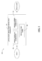
- Fig. 1 illustrates an example system that enables constructing an automation application for utilization in an industrial automation environment.
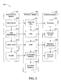
- Fig. 2 illustrates an example depiction of the S88 model.
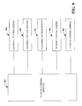
- Fig. 3 illustrates an example application that can be constructed by utilizing design template(s) and design pattern(s).
- Fig. 4 illustrates an example table of design patterns.
- Fig. 5 illustrates an example system that enables building an automation application by utilizing a design template framework with a library of design patterns.
- Fig. 6 illustrates an example methodology that facilitates building an automation application for utilization in an industrial automation environment.
- Fig. 7 illustrates an example methodology that facilitates rendering a design pattern table that can be utilized to construct an automation application.
- Fig. 8 is a diagram illustrating module attributes.
- Fig. 9 is a diagram illustrating example resource control modules.
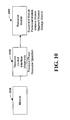
- Fig. 10 is a diagram illustrating a resource module.
- Fig. 11 is a diagram illustrating example resource modules.
- Fig. 12 is a diagram illustrating a resource control model.
- a component may be, but is not limited to being, a process running on a processor, a processor, an object, an executable, a thread of execution, a program and a computer.
- an application running on a server and the server can be components.
- One or more components may reside within a process and/or thread of execution and a component may be localized on one computer and/or distributed between two or more computers, industrial controllers, and/or modules communicating therewith.
- the system 100 includes an automation application generation component 102 that leverages an obtained input to build the automation application.
- the input can be obtained from any source (not shown) ( e . g ., the input can be automatically generated, manually provided, ).
- the automation application that is yielded can be utilized in a manufacturing execution system (MES) to measure and/or control production activities.
- MES manufacturing execution system
- the automation application generation component 102 can select various modules from a set of modules to be employed in connection with the application.
- the automation application generation component 102 can automatically identify and select application modules (e.g. , for a system designer) relating to the application.
- automatic identification of appropriate modules by utilizing the automation application generation component 102 can reduce time, cost, etc. associated with coding a particular application ( e . g ., in comparison to techniques whereby module(s) to be incorporated into the application are selected via trial and error and/or the application is built by a system designer writing custom code).
- the automation application generation component 102 can further include a design template component 104, a design pattern component 106, and a design pattern table 108.
- the design template component 104 can provide a framework (e . g ., design template) to be employed in connection with yielding the application.
- the design template can leverage a limited scope of modules to form a consistent design framework.
- the design template can provide a modular, hierarchical framework.
- the design template can be built from highly reusable module classes, which for example can observe the ISA 88.01 defined module relationships. However, it can be appreciated that design templates can form any relational hierarchy.
- the design template component 104 can utilize a plurality of disparate classes of design templates.
- the design template component 104 can provide a constant framework that can thereafter be tailored ( e . g ., based upon the input obtained by the automation application generation component 102, by the design pattern component 106, ...) to create the application.
- Design templates (and a plurality of design templates) can be self describing, and can present contextual information regarding its interface to the design template component 104.
- the design pattern component 106 can integrate a design pattern (or a plurality of design patterns) with the design template to construct the application. Moreover, the design pattern component 106 can identify, recommend, select, etc. a design pattern to be integrated with the application being generated. For instance, the design pattern component 106 can select a design pattern from the design pattern table 108 identified as being able to accomplish a particular function, task, etc . The design pattern component 106 can automatically select a design pattern to be utilized in an application being generated, for example; thereafter, the chosen design pattern can be automatically integrated into the application. According to another illustration, the design pattern component 106 can recommend a design pattern ( e.g. , to a developer) to be employed in the application.
- a design pattern e.g. , to a developer
- the design pattern component 106 can consider contextual data, information related to the application being built, data related to the design template yielded by the design template component 104, etc. in connection with determining the recommended design pattern. Moreover, the design pattern component 106 can utilize an input from a user to select a design pattern.
- a design pattern can include functional details that can be classified as: general description, equipment used, sequence of operation, exceptions handling, process parameters, process data, operator interactions, process inputs, and process outputs.
- a design pattern can include design details (e . g ., that can be defined by a project engineer) related to the following: module definition (classes and numbers), sequencing, addressing, parameter definition (extensions to the design template), and report definition (extensions to the design template).
- the design pattern can include test scripts to test defined functionality, where the testing can relate to device sequencing, parameters, reports and/or exceptions.
- the design pattern can also include cost attributes such as a baseline cost (e.g. , cost that represents the value of the design pattern), installation effort (e.g. , based on the complexity of the design pattern), and/or extension effort (e.g. , based on the defined changes to the baseline functionality provided with the design pattern).
- the design pattern can also include application details which allow the functional and design components to automatically generate the application.
- the design pattern table 108 can include a library of the common design patterns. Moreover, the design pattern table 108 can be organized in a manner that classifies the design patterns. For example, the design pattern table 108 can classify the design patterns based upon process characteristics, design characteristics, cost characteristics, and so forth since the design patterns can represent a multitude of information. According to an illustration, the design pattern table 108 can graphically represent the classifications of the design patterns, and this graphical representation can be employed to identify, select, present recommendations, etc. of design patterns for utilization in the application being constructed. Also, the design pattern table 108 can graphically represent relationships and/or similarities between design patterns. By providing a manner for classifying design patterns, the design pattern table 108 can reduce duplication of design patterns and/or can simply identification, selection, recommendation, etc. of design patterns.
- An application e.g. , discrete, continuous, batch, (7) can be functionally decomposed, and the logical point to perform the functional decomposition of an application is at the process action level (e.g. , from the S88 process model described in Fig. 2).
- process e.g. , discrete, continuous, batch, ...) capabilities of the application can be described as fundamental elements.
- the fundamental elements can be the design patterns included in the design pattern table 108.
- the design patterns can be functional blocks chosen by the design pattern component 106 while building an application.
- the process model is achieved by applying the procedural model to the physical model.
- a limited scope of modules can be utilized to form a consistent design framework or design template that can be leveraged by the design template component 104.
- the design template allows for procedural control from a recipe or from equipment procedures. Whether acted on by an equipment operation, as in discrete manufacturing and continuous process applications, or by a recipe phase as in batching applications, an equipment phase ( e . g ., as defined by ISA 88.01) is the logical extension point to external procedural control from the design template.
- design patterns e.g. , chosen by the design pattern component 106.
- design patterns in turn can be applied to design templates to provide control of associated equipment.
- the time required to build an application can be reduced.
- pre-validation of design templates and design patterns can mitigate software validation time (e . g ., required within the life sciences industry, ). It can also be appreciated that the cost estimate component of a design pattern can be updated over time by continuous feedback on the implementation and extension effort, thus dramatically improving cost estimates and lowering costs by improving the design patterns to reduce extension effort.
- the automation application generation component 102, the design template component 104, the design pattern component 106, and/or the design pattern table 108 can relate to module components (not shown) and/or phase components (not shown).
- the module components or phase components can be an association of logic with one or more resources.
- the logic includes program code that can alter the state of a resource for example, ladder code, function block, structured text, function chart, script, JAVA, C code, and so forth.
- the resources are those components or elements that perform an activity in a system including equipment and personnel that perform work in a system. Other examples of types of resources include Equipment, Material, Personnel, Segments and Storage. Personnel and equipment (machines) can perform activities in a system.
- Resources that can perform work can be classified as active resources (e . g ., CNC machine, Injection molding machine), whereas other equipment resources can be considered passive resources (e.g. , sensor, material).
- active resources e.g., CNC machine, Injection molding machine
- passive resources e.g. , sensor, material
- the modules hide the user from internal interfaces, messages, and logic specific to the resources yet provide standard or generic interfaces to external systems or between components.
- Modules may include other modules including nested modules where standard module behaviors and attribute patterns can be represented using common data model representations for module classes, module templates and module inheritance. Module classes and templates can be maintained in libraries which facilitate access to desired system functionality and further promote system integration. Resources can have various states associated therewith such as common S88 state classifications including idle, hold, abort, run, reset, stop, restart, and so forth where the module can present logic to represent state machines that manage the state of the resource.
- resource modules (described below) can take on the name of the resource that is the primary focus on the module. For example, an Equipment module is primarily focused on coordination of equipment but may involve personnel in the process. Similarly, a Personnel module is focused on coordination of personnel but may involve other resources in the process.
- a Control Module that manages a material may be referred to as a Material Control Module and so forth.
- components associated with the system 100 can include various computer or network components such as servers, clients, programmable logic controllers (PLCs), communications modules, mobile computers, wireless components, control components and so forth which are capable of interacting across a network.
- PLC programmable logic controllers
- the term PLC as used herein can include functionality that can be shared across multiple components, systems, and/or networks.
- one or more PLCs can communicate and cooperate with various network devices across the network. This can include substantially any type of control, communications module, computer, I/O device, sensor, Human Machine Interface (HMI) that communicate via the network which includes control, automation, and/or public networks.
- the PLC can also communicate to and control various other devices such as Input/Output modules including Analog, Digital, Programmed/Intelligent I/O modules, other programmable controllers, communications modules, sensors, output devices, and the like.
- the network can include public networks such as the Internet, Intranets, and automation networks such as Control and Information Protocol (CIP) networks including DeviceNet and ControlNet. Other networks include Ethernet, DH/DH+, Remote I/O, Fieldbus, Modbus, Profibus, wireless networks, serial protocols, and so forth.
- the network devices can include various possibilities (hardware and/or software components). These include components such as switches with virtual local area network (VLAN) capability, LANs, WANs, proxies, gateways, routers, firewalls, virtual private network (VPN) devices, servers, clients, computers, configuration tools, monitoring tools, and/or other devices.
- VLAN virtual local area network
- WANs wide area network
- proxies proxies
- gateways gateways
- routers firewalls
- VPN virtual private network
- the S88 model 200 can represent equipment and procedures for use in automated batch processes.
- the S88 model 200 includes a procedural model 202, a physical model 204, and a process model 206.
- the procedural model 202 is structured as a hierarchical ranking of procedures 208.
- Each procedure 208 includes one or more unit procedures 210 ( e . g ., each unit procedure 210 can control the function of a unit).
- each unit procedure 210 can further include one or more operations 212, which in turn can include one or more phases 214.
- An operation 212 is a procedural element defining an independent processing activity that includes the algorithm for initiation, organization, and control of phases.
- the phase 214 is the lowest level in the procedural control model and can perform a process function on an equipment module and/or can coordinate control of control module(s).
- the physical model 204 includes a process cell 216 that can include production and supporting equipment utilized to make a batch of product.
- the process cell 216 comprises one or more units 218, which can be equipment that performs specific tasks within the process.
- Each unit 218 further includes one or more units 220.
- each unit 220 can comprise one or more equipment modules 222, each of which in turn can include one or more control modules 224.
- the design templates described herein can map to the equipment module(s) 222 and the control module(s) 224 of the S88 model 200. As such, the design templates can provide a modular, hierarchical framework. Additionally, design modular decomposition can support the design template.
- the process model 206 of the S88 model 200 includes a process 226.
- the process 226 includes one or more process stages 228, each of which can further include one or more process operations 230. Additionally, each process operation 230 includes one or more process actions 232.
- the design patterns described herein can map to the process actions 232. For example, each design pattern can provide a functional description of the corresponding process action 232. Thus, the design pattern can yield design parameters to apply to the design template.
- the application 300 includes a design template 302 that provides a framework for the application 300.
- the design template 302 can be provided, selected, built, etc. by the design template component 104 of Fig. 1.
- the design template can be constructed from highly reusable module classes.
- the design template 302 can include various module(s) ( e . g ., equipment modules, control modules, resource modules, ...) and phase(s).
- the design template 302 includes an equipment module 304, an equipment phase 306, and a plurality of control modules 308; it is to be appreciated, however, that the claimed subject matter is not limited to this example design template.
- the equipment module 304 includes an equipment phase (EP) interface 310, a unit interface 312, an equipment interface 314, and mode data, permissive data, and command/status data 316.
- the EP interface 310, unit interface 312, equipment interface 314, and mode data, permissive data, and command/status data 316 can utilize reusable module classes. It is to be appreciated that the equipment module 304 is exemplary in nature and that other types of modules and/or classes are possible.
- the EP interface 310 provides a linkage to/from the equipment phase 306.
- the EP interface 310 determines how the equipment module 304 interacts with the equipment phase 306.
- a standard EP interface 310 can be created that applies to all equipment module classes. For instance, the EP interface 310 can provide a mechanism to pass report/parameter data between the equipment phase 306 and the equipment module 304. Additionally or alternatively, the EP interface 310 can obtain human requests.
- the unit interface 312 provides a linkage to/from a respective unit (not shown) ( e . g ., as described in a typical S88/S95 procedure).
- the unit interface 312 determines how the equipment module 304 interacts with the unit.
- a standard unit interface 312 can be created that applies to all equipment module classes. For instance, the equipment module 304 can be aware of an associated unit such that propagation of mode and faults can traverse via the unit interface 312.
- the equipment interface 314 provides linkage to/from subordinate equipment modules (not shown) and/or control modules 308.
- the equipment interface 314 determines how the equipment module 304 interacts with these subordinate equipment modules and/or control modules 308.
- a standard equipment interface 314 can be created that applies to the equipment module class.
- mode data, permissive data, and command/status data 316 can be included in the equipment module 304. These class components can be passed to/from the respective interfaces associated with the equipment module 304.
- the equipment module 304 includes a coordination and sequencing design pattern 318.
- Coordination control and sequencing of equipment can refer to logic associated with commanding the state of subordinate equipment/control modules.
- coordination and sequencing is facilitated via the equipment interface 314.
- the coordination and sequencing design pattern 318 can be selected ( e . g ., from a library of design patterns) and thereafter integrated with the template 302 to yield the application.
- the equipment phase 306 can interface with the equipment module 304. It is to be appreciated that the equipment phase 306 is exemplary in nature and that other types of phases and/or classes are possible.
- the equipment phase 306 includes a phase manager 320.
- the phase manager 320 can provide various interfaces (not shown) (e.g. , a phase interface to link with a recipe phase to control a process, an equipment module interface to link with the equipment module 304, ).
- the phase manager 320 can obtain input from batch processing software, a ControlLogix system, sequential function charts (SFC's), and so forth.
- the phase manager 320 can be built from reusable module classes.
- the equipment phase 306 additionally includes a report/parameters design pattern 322.
- the report/parameters design pattern 322 can include functional details, design details, testing scripts, cost data, and so forth to carry out a process action.
- the report/parameters design pattern 322 can deliver extensions to variables ( e . g ., parameters and report variables) included as part of the design template 302.
- each of the control modules 308 can include basic controls 324.
- the basic controls 324 can be included in the design template 302 and can be built from reusable module classes.
- disparate design templates similar to the design template 302 can be employed.
- a similar MES design template can be utilized that allows the design patterns to be extended to cover certain related details with the information layer; however, the claimed subject matter is not so limited.
- the design patterns are organized within the table 400 based upon various functions, criteria, etc. For instance, the design patterns can represent a multitude of information, and therefore, the design patterns can be classified in a number of manners.
- the design pattern table 400 can graphically depict relationships between design patterns, design pattern similarities and/or differences, costs, and so forth.
- the table 400 can include all of the design patterns in a library of design patterns or a subset thereof.
- design pattern table 400 is provided as an example, and the claimed subject matter is not so limited; for example, any disparate design patterns can be included in a similar design pattern table, a design pattern table need not include one or more of the design patterns of table 400, and/or any differing type of organization, classification, etc. can be employed therewith.
- the design patterns can be classified based upon process characteristics, design characteristics, and/or cost characteristics.
- the process characteristics can relate to a type of process function provided by the design pattern such as, for instance, whether the design pattern pertains to transferring material, transforming material, or a time/event.
- nearby columns can include design patterns classed in a particular process function type, while design patterns in the same column can be most similar.
- the design patterns for transferring material are included in the two left columns (e.g. , vessel to vessel transfer, route, convey, recirculate, empty, fill, dose (blend), manual (hand) addition, and transfer (add)).
- the design patterns pertaining to transforming material are included in the middle three columns of the table 400 (e . g ., vaporize, evaporate, heat, cool, pressurize, depressurize, torque, filter, aerate, mix, and agitate). Meanwhile, the design patterns that relate to a time/event are included in the two right columns of the table 400 (e.g. , initialize, final, wait, test (inspect), prompt, clamp/unclamp, lift/locate, scan, RFID, and part pick).
- design characteristics can characterize design details associated with the design patterns.
- the shading represents the design characteristic category.
- the design characteristics can relate to equipment verification, generic, material transfer, and discrete.
- design patterns related to equipment verification can include vessel to vessel transfer, initialize and final.
- Generic design patterns can include vaporize, evaporate, heat, cool, pressurize, depressurize, filter, aerate, mix, agitate, wait, test (inspect), and prompt.
- Design patterns pertaining to material transfer can include route, convey, recirculate, empty, fill, dose (blend), manual (hand) addition, transfer (add).
- discrete design patterns can include torque, clamp/unclamp, lift/locate, scan, RFID, and part pick.
- the table 400 can also include information related to cost characteristics. Although not shown, it is contemplated that a numeric value for each design pattern can be included in the table 400 that indicates a base line cost of the design pattern. Pursuant to a further example, the table 400 can include a numeric value (not shown) indicating the effort ( e . g ., man hours) to implement the design pattern; this cost can be referred to as implementation effort.
- Fig. 5 illustrates a system 500 that enables building an automation application by utilizing a design template framework with a library of design patterns.
- the system 500 includes the automation application generation component 102, which further comprises the design template component 104, the design pattern component 106, and the design pattern table 108.
- the system 500 further includes a presentation component 502 that provides various types of user interfaces to facilitate interaction between a user and any component associated with the automation application generation component 102.
- the presentation component 502 is a separate entity that can be utilized with the automation application generation component 102.
- the presentation component 502 and/or similar view components can be incorporated into the automation application generation component 102 and/or a stand-alone unit.
- the presentation component 502 can provide one or more graphical user interfaces (GUIs), command line interfaces, and the like.
- GUIs graphical user interfaces
- a GUI can be rendered that provides a user with a region or means to load, import, read, etc., data, and can include a region to present the results of such.
- regions can comprise known text and/or graphic regions comprising dialogue boxes, static controls, drop-down-menus, list boxes, pop-up menus, as edit controls, combo boxes, radio buttons, check boxes, push buttons, and graphic boxes.
- utilities to facilitate the presentation such as vertical and/or horizontal scroll bars for navigation and toolbar buttons to determine whether a region will be viewable can be employed.
- the user can interact with one or more of the components coupled and/or incorporated into the automation application generation component 102.
- the design pattern table 108 can be displayed to and/or interacted with by the user to enable constructing an application with the automation application generation component 102.
- the user can also interact with the regions to select and provide information via various devices such as a mouse, a roller ball, a keypad, a keyboard, a pen and/or voice activation, for example.
- a mechanism such as a push button or the enter key on the keyboard can be employed subsequent entering the information in order to initiate the search.
- a command line interface can be employed.
- the command line interface can prompt ( e . g ., via a text message on a display and an audio tone) the user for information via providing a text message.
- command line interface can be employed in connection with a GUI and/or API.
- command line interface can be employed in connection with hardware (e . g ., video cards) and/or displays ( e . g ., black and white, and EGA) with limited graphic support, and/or low bandwidth communication channels.
- FIGs. 6-7 methodologies in accordance with various aspects of the claimed subject matter are illustrated. While, for purposes of simplicity of explanation, the methodologies are shown and described as a series of acts, it is to be understood and appreciated that the claimed subject matter is not limited by the order of acts, as some acts may occur in different orders and/or concurrently with other acts from that shown and described herein. For example, those skilled in the art will understand and appreciate that a methodology could alternatively be represented as a series of interrelated states or events, such as in a state diagram. Moreover, not all illustrated acts may be required to implement a methodology in accordance with the claimed subject matter.
- a framework of an automation application can be constructed based upon a design template.
- the design template can provide a consistent design framework.
- the design template can be built from reusable module classes (e.g. , which can observe the ISA 88.01 defined module relationships). Additionally, the design template can map to equipment module(s) and/or control module(s) in the S88 model.
- a particular design pattern from a table that represents classifications of a plurality of design patterns can be selected.
- the table can include a library of common design patterns. For instance, the design patterns can describe fundamental elements of the application.
- the particular design pattern can automatically be selected and/or manually be selected ( e . g ., in response to a user choice, ).
- design pattern recommendations can be yielded, and the recommendations can prompt user selection (or non-selection).
- the table can be rendered to display relationships between the plurality of design patterns.
- the application can be generated by integrating the particular design pattern with the framework created from the design template.
- the design pattern can be utilized to provide information utilized to carry out a process action as opposed to a developer having to code such information.
- a cost estimate, a functional specification, design documentation, a test specification, validation documentation, etc. can be generated for the application.
- a methodology 700 that facilitates rendering a design pattern table that can be utilized to construct an automation application.
- a set of design patterns can be classified according to respective process characteristics and design characteristics.
- each design pattern can be determined to be associated with a particular process characteristic (e . g ., process function) such as transferring material, transforming material, or time/event.
- each design pattern can be categorized according to design characteristics (e.g. , equipment verify, generic, material transfer, discrete).
- subsets of design patterns classified within each category of process characteristics can be graphically represented in a design pattern table.
- subsets of design patterns classified within each category of design characteristics can be graphically represented in the design pattern table. Accordingly, relationships between design patterns can be depicted in a rendered design pattern table. Moreover, one or more design patterns can be selected based upon the relationships illustrated in the rendered design pattern table.
- module attributes 800 are illustrated.
- the attributes 800 depicted in Fig. 8 include a common (or exemplary) representation that can be modules from modules. Generally, a set of standard attributes can be determined that are common to all modules. Similarly, for other types of modules described below, additional standard attributes can be defined.
- An example of a property 810 available on modules includes attributes such as Fault and Status at 814. Active resource modules (e . g ., equipment and personnel) can support additional properties 810 such as available / unavailable.
- Attributes presented below are represented as associations from the module to objects which may be internal in a common data model or elsewhere (e.g., CAD Files).
- standard public interfaces can be provided. These interfaces 820 publish verbs 824 that are available to external systems and are documented activities that hide the complexity of the underlying code used to implement the interface. Interfaces 820 can be associated with various common usage scenarios. For example, interfaces 820 can be used as access points that can hook in real time diagnostics, security and so forth.
- Public verbs 824 initiate an action within the module.
- the activity is described to clients of the interface 820.
- the implementation is considered private and is not presented to clients. Examples can include Open, Stop, Abort, Shut, and so forth.
- a data value property 810 provides public access to information that is used by the module during its operation and can be provided by request values and/or internal values (or an equivalent). The association of logic to transfer request values to internal values and vice versa are referred to as get and set logic for the value. It is noted that in a controller, if there is not a set routine to transfer request values to internal values, the internal value can overwrite the request value on the next scan providing read only capability.
- the properties 810 can be considered in at least two classifications. States have special significance for production systems and can have a specific set of values that can be represented by range or enumeration.
- a state can represent the current status of the primary resource being encapsulated by the module e.g. , Percent open, Mode, Service (in, out), and so forth.
- Information that is used by the module during its operation includes access to data that is provided by interfaces 820, e.g. , Conversion Map, Name, Description, expiry date, personnel contact information.
- Some properties 810 can be common to all instances of resource modules (e.g. , scanned copy of resource specification documents), whereas other properties 810 are specific to each module instance (e.g., Status, percent open).
- internal resource interfaces include interfaces from logic 840 in the module to the resource being managed at 850, where the logic includes code and/or configuration(s) that process a command and/or update state and data properties. In some cases, this can be hardware such as I/O interfaces, or in other cases it is to subordinate resource control modules that have direct interfaces. Some examples include I/O mapping, material management logic routines, and so forth.
- These interfaces 830 are internal to the module and can enable the public interfaces 820 and properties 810 to be the boundary to other system components. Modules that wrap different resources but support the same public properties/interfaces can be exchanged without disrupting interfaces to other components. Generally, I/O mapping and system messaging interfaces are exposed during deployment bind processes. When bound, external interfaces 820 to runtime systems may then consider these interfaces as internal.
- alarm and event messages can be provided which include messages that can be exposed as runtime messages visible to external systems during the execution of the module. This includes alarms and events explicitly coded by the developer and system messages promoted to be visible by external systems.
- one or more artifacts include information that document the operation and structure of the resource such as, for example, wiring diagrams, warranties, payroll, parts supplier information, and so forth.
- Visualization aspects include associated graphics that present the resource state and properties to applications interacting with the resource.
- the artifacts can include faceplates, icons, state overlays, edit dialogs, help files, etc.
- system messages allow modules to listen for and publish data model messages to external components. Inbound messages are typically used to manage modules (configure, initialize, propagate properties, and so forth) and publish messages on module activity (resource state, data model messages, and so forth).
- resource control modules 900 provide simple control of one or more resources.
- the resource control module (RCM) 900 represents the logic to manage the state or data of the resource and may include other resource control modules to achieve its respective functionality.
- the RCM 900 provides public interfaces via actions and properties. In some cases, an action may be a simple bit value or a request value that is interfaced to internal values in the module and in other cases more complex logic can be provided.
- the RCM 900 can include other resource control modules and may promote a command to be represented as segment resource control interface.
- Example forms of the RCM 900 include the following.
- the equipment control module 910 can encapsulate the equipment and its control such as control of values, drives, and so forth.
- a Material Control Module (MCM) can be provided. Management of material resource instances which are represented as sub-lots including change in location, quality status, availability, order status, logic that can be performed on material sub-lots, generation of material events such as consumed, produced and moved events, sub-lot combination, expiry dates, and so forth.
- a Personnel Control Module (PCM) is provided. This includes management of individual people such as Active, Idle, Break states directly or via shift schedules. This also includes data associated with people such as shift time patterns, for example. Other attributes that may be managed by PCM 930 are a person's location in a plant (GPS), qualification checks, or current assignment, for example.
- a Segment Control Module (SCM) includes manipulation of simple segment tasks such as piping paths, AGV paths, device state machines, robotic sequences and so forth. The SCM 940 typically performs an action on one segment such as next step to execute after the current step.
- a Storage Control Module (STGCM) includes manipulation of simple storage logic such as buffer capacity and ordering into and out of a queue for the respective storage unit or requirement.
- Fig. 10 illustrates a resource module 1000 for an industrial control system.
- Resource modules 1000 extend resource control modules described above to enable coordination of resources (e.g. , equipment, people, modules, ).
- the resource control module 1000 includes a module 1010 and a resource control interface 1020.
- Resource modules 1000 are also able to represent more complex activities than resource control modules.
- resource modules 1000 may include other resource control modules at 1010 and/or other resource modules.
- an equipment module may leverage a subordinate material control module to represent material handling aspects or a segment module to solicit an electronic signature.
- a configuration module may include management definitions and configuration of resources - personnel, material, equipment, segments, storage, and so forth.
- Another type of module includes nested modules where a module references other modules. These modules may be children of a parent module or shared from one module to another.
- Resource modules may include resource control modules; however, resource control modules should not include resource modules.
- Modules can include modules focused on other resource types; for example, an equipment module may include equipment modules and material modules.
- Fig. 11 illustrates example resource modules 1100 for an industrial control system.
- an Equipment Module provides coordination of equipment modules and equipment control modules to perform a process-orientated task independent of specific material e . g ., In-feed, AGV controller, Conveyor, and so forth.
- a Material Module provides coordination of material modules and material control modules to perform material focused tasks e.g. , material reservation, provision, material mass balance calculation, bill of material management, work order management, and so forth.
- a Personnel Module provides coordination of personnel modules and personnel control modules to perform personnel focused tasks e.g. , electronic signature collection, security validation, certification validation, manual control interactions, and so forth.
- a Segment Module provides coordination of segment modules and segment control modules to execute sequences of tasks represented by segments. Segments define resource requirements and ordering that can represent most production and process activities. This module provides access to more complex tasks that require specific sequences to be followed e . g ., Process Analytics Technology (PAT) integration, electronic signatures collection, defect, process deviation and fault recovery processing. The segment module 1140 may also construct a sequence to be followed that can be applied as manual, automatic or semi automatic sequences (e.g. , route, recipe execution).
- a Storage Module provides coordination of storage related activities, allocation of storage to requestors, modeling of inventory calculations and so forth. This also includes interaction with higher-level systems that manage storage and inventory information.
- Fig. 12 illustrates an example resource control model 1200 for an industrial control system.
- Resource Control Interfaces are the interfaces exposed to production management systems for resource binding and arbitration purposes.
- the interfaces are elements of the resource control model 1200 including procedures, operations or phases. These interfaces are made available by exposure via one or more capabilities 1210 described below.
- Procedures, operations and phases depicted in this model 1200 are commonly referred to in association with their module resource type such as Equipment Phase, Personnel Phase, Segment Phase, or as a generic Resource Phase where no specific resource module is required.
- Production management including Product Production Rules (production route or control recipe) physically bind to (reference) resource control phases to perform work.
- the availability of other resources 1220 such as material, equipment, personnel, etc. are considered during the binding process of product production rules to work centers (e.g. , production lines, process cells, ). These selection processes evaluate resource capabilities to locate the appropriate resource for the task.
- Resource capabilities 1210 include the resource 1220 required to perform work in a production system. Consequently, resources 1220 are at the center of efficiency, capacity, scheduling and arbitration considerations.
- a resource's ability to work or be available to allow work to commence is represented as resource capability at 1230.
- the existence of capability 1230 associated with a resource 1220 does not make the resource available for production; the resource's capability 1230 is associated with organizational units 1240 that can support the respective resource capability. For example, an operator (personnel resource) may have qualifications for a Mixer in line 1, where this qualification capability is only in effect with that specific mixer unless explicitly directed.
- Resource arbitration algorithms can search for resource capabilities 1230 in the scope of organizational units 1240 they are to be executed within.
- Resources 1220 publish capabilities to organizational units 1240 for use by system processes in a given scope. Modules are a type of resource and can be accessed directly by published capabilities 1210. However, a more common interface to Resource Modules is via verbs that are supported by the Resource Module noted above. These verbs are Resource Control elements (phases, operations, procedures ...) which are segments. A published capability of a resource module is typically one of the phases supported the module. Resource control interfaces are published (made available) to the outside world as capabilities 1210. Resource modules provide the ability to promote a command to become a resource control interface.
- Some process control systems are built using only Resource control modules (especially control modules). Examples of this are continuous processes such as petrochemical and heavy chemical plants. In order to initiate, the process takes a plant up to its running state or makes a change to the state of a series of commands that are initiated and coordinated to achieve the new state. It is also possible to promote commands from resource control modules to appear as capabilities that can be accessed as "tuning knobs" for tweaking the system between system states. As shown in the model 1200, the resource 1220 and capability can be associated with a higher-level class or abstraction 1250.
- the claimed subject matter may be implemented as a method, apparatus, or article of manufacture using standard programming and/or engineering techniques to produce software, firmware, hardware, or any combination thereof to control a computer to implement the disclosed subject matter.
- article of manufacture as used herein is intended to encompass a computer program accessible from any computer-readable device, carrier, or media.
- computer readable media can include but are not limited to magnetic storage devices (e.g. , hard disk, floppy disk, magnetic strips%), optical disks (e . g ., compact disk (CD), digital versatile disk (DVD)...), smart cards, and flash memory devices (e.g. , card, stick, key drive).
- a carrier wave can be employed to carry computer-readable electronic data such as those used in transmitting and receiving electronic mail or in accessing a network such as the Internet or a local area network (LAN).
- LAN local area network
- the terms (including a reference to a "means") used to describe such components are intended to correspond, unless otherwise indicated, to any component which performs the specified function of the described component (e.g. , a functional equivalent), even though not structurally equivalent to the disclosed structure, which performs the function in the herein illustrated exemplary aspects of the claimed subject matter.
- the innovation includes a system as well as a computer-readable medium having computer-executable instructions for performing the acts and/or events of the various methods of the claimed subject matter.
- a design template component can provide a design template to yield a modular, hierarchical framework for an application.
- a design pattern table can include a library of design patterns, where the design patterns can be organized according to respective classifications.
- a design pattern component can integrate a selected design pattern from the design pattern table with the design template to construct the application.
Landscapes
- Physics & Mathematics (AREA)
- General Physics & Mathematics (AREA)
- Engineering & Computer Science (AREA)
- Automation & Control Theory (AREA)
- Stored Programmes (AREA)
Applications Claiming Priority (3)
| Application Number | Priority Date | Filing Date | Title |
|---|---|---|---|
| US86240306P | 2006-10-20 | 2006-10-20 | |
| US89097307P | 2007-02-21 | 2007-02-21 | |
| US11/864,733 US7676292B2 (en) | 2006-10-20 | 2007-09-28 | Patterns employed for module design |
Publications (3)
| Publication Number | Publication Date |
|---|---|
| EP1914610A2 true EP1914610A2 (de) | 2008-04-23 |
| EP1914610A3 EP1914610A3 (de) | 2013-01-23 |
| EP1914610B1 EP1914610B1 (de) | 2017-12-06 |
Family
ID=39039549
Family Applications (1)
| Application Number | Title | Priority Date | Filing Date |
|---|---|---|---|
| EP07118956.7A Ceased EP1914610B1 (de) | 2006-10-20 | 2007-10-22 | Ausführungsmuster zur modularen Programmierung |
Country Status (2)
| Country | Link |
|---|---|
| US (1) | US7676292B2 (de) |
| EP (1) | EP1914610B1 (de) |
Cited By (5)
| Publication number | Priority date | Publication date | Assignee | Title |
|---|---|---|---|---|
| EP2711794A1 (de) * | 2012-09-25 | 2014-03-26 | dSPACE digital signal processing and control engineering GmbH | Verfahren zur zeitweiligen Separierung von Objektdaten von Entwurfsmodellen |
| EP2866105A1 (de) * | 2013-10-24 | 2015-04-29 | Siemens Aktiengesellschaft | Verfahren zur Generierung von Automatisierungsprogrammen |
| CN111240209A (zh) * | 2020-03-16 | 2020-06-05 | 广东工业大学 | 构型动型控型优型联动响应的自适应组态方法及系统 |
| US10754667B1 (en) | 2019-03-20 | 2020-08-25 | Yokogawa Electric Corporation | System and method of module engineering for an industrial process |
| CN120428678A (zh) * | 2025-05-15 | 2025-08-05 | 浙江聚创精密制造有限公司 | 一种基于大数据的线控制动的冗余控制方法与系统 |
Families Citing this family (16)
| Publication number | Priority date | Publication date | Assignee | Title |
|---|---|---|---|---|
| US8914679B2 (en) * | 2006-02-28 | 2014-12-16 | International Business Machines Corporation | Software testing automation framework |
| US8677310B2 (en) * | 2008-06-30 | 2014-03-18 | Rockwell Automation Technologies, Inc. | Industry template abstracting and creation for use in industrial automation and information solutions |
| US9335761B2 (en) * | 2008-09-30 | 2016-05-10 | Rockwell Automation Technologies, Inc. | Procedure classification for industrial automation |
| EP2216695B1 (de) * | 2009-02-09 | 2013-03-27 | Siemens Aktiengesellschaft | Verfahren zum Betrieb eines Automatisierungssystems, korrespondierendes Computerprogramm und System oder Gerät, das nach dem Verfahren arbeitet |
| US9256219B2 (en) * | 2009-08-11 | 2016-02-09 | Fisher-Rosemount Systems, Inc. | System configuration using templates |
| US9292941B2 (en) * | 2009-09-04 | 2016-03-22 | Adobe Systems Incorporated | Methods and apparatus for specifying and interpolating hierarchical procedural models |
| US8572567B2 (en) | 2010-06-16 | 2013-10-29 | International Business Machines Corporation | Specifying and processing composed patterns |
| US9348967B2 (en) * | 2012-01-19 | 2016-05-24 | Oracle International Corporation | Overlaying business intelligence data on a product design visualization |
| US9292260B2 (en) * | 2012-06-22 | 2016-03-22 | Oracle International Corporation | Method and system for implementing a pattern viewer |
| EP3239793B1 (de) | 2014-12-26 | 2020-11-25 | Kawasaki Jukogyo Kabushiki Kaisha | Verfahren zur erzeugung eines roboterbetriebsprogramms und vorrichtung zur erzeugung eines roboterbetriebsprogramms |
| RU2747824C2 (ru) * | 2015-10-13 | 2021-05-14 | Шнейдер Электрик Системз Юэсэй, Инк. | Системы и способы разработки и оптимизации приложений для управления иерархическими интеллектуальными активами |
| US11301595B2 (en) | 2016-09-29 | 2022-04-12 | Autodesk, Inc. | Knowledge-based alternative design recommendations |
| US10466978B1 (en) * | 2016-11-30 | 2019-11-05 | Composable Analytics, Inc. | Intelligent assistant for automating recommendations for analytics programs |
| US12019742B1 (en) | 2018-06-01 | 2024-06-25 | Amazon Technologies, Inc. | Automated threat modeling using application relationships |
| US12174963B1 (en) * | 2018-10-29 | 2024-12-24 | Amazon Technologies, Inc. | Automated selection of secure design patterns |
| US12420408B1 (en) * | 2020-07-17 | 2025-09-23 | Bright Machines, Inc. | Human machine interface recipe building system for a robotic manufacturing system |
Citations (1)
| Publication number | Priority date | Publication date | Assignee | Title |
|---|---|---|---|---|
| US206761A (en) | 1878-08-06 | Improvement in glory-hole furnaces for finishing glassware |
Family Cites Families (76)
| Publication number | Priority date | Publication date | Assignee | Title |
|---|---|---|---|---|
| US4071697A (en) * | 1976-10-18 | 1978-01-31 | Atari, Inc. | Interactive video/telephone transmission system |
| US4215396A (en) * | 1978-08-24 | 1980-07-29 | Texas Instruments Incorporated | Intelligent programmable process control system |
| US4570217A (en) * | 1982-03-29 | 1986-02-11 | Allen Bruce S | Man machine interface |
| US4519027A (en) * | 1982-06-10 | 1985-05-21 | Cybersonic Corporation | Industrial control, communications and information system |
| US4910691A (en) * | 1987-09-30 | 1990-03-20 | E.I. Du Pont De Nemours & Co. | Process control system with multiple module sequence options |
| US5068778A (en) | 1988-11-28 | 1991-11-26 | Reliance Electric Industrial Company | Industrial control system device |
| US5058043A (en) * | 1989-04-05 | 1991-10-15 | E. I. Du Pont De Nemours & Co. (Inc.) | Batch process control using expert systems |
| FR2654286B1 (fr) * | 1989-11-03 | 1995-06-16 | Europ Rech Electr Lab | Procede de validation instantanee d'actions dans le cadre d'emissions televisees et dispositif de mise en óoeuvre. |
| EP0456218B1 (de) | 1990-05-11 | 1997-01-15 | Hitachi, Ltd. | Automatisierte Produktionsstrasse |
| US5255197A (en) * | 1990-07-06 | 1993-10-19 | Honda Giken Kogyo Kabushiki Kaisha | Line production management system |
| US5214577A (en) * | 1990-10-24 | 1993-05-25 | Osaka Gas Co., Ltd. | Automatic test generation for model-based real-time fault diagnostic systems |
| JPH06266727A (ja) * | 1990-10-24 | 1994-09-22 | Osaka Gas Co Ltd | 診断表示方法及び表示装置 |
| US5303393A (en) * | 1990-11-06 | 1994-04-12 | Radio Satellite Corporation | Integrated radio satellite response system and method |
| DE4139179C2 (de) * | 1991-11-28 | 1994-01-13 | Wacker Chemie Gmbh | Verfahren zur automatischen Steuerung von Chargenprozessen |
| US5388318A (en) * | 1992-10-09 | 1995-02-14 | Laharco, Inc. | Method for defining a template for assembling a structure |
| US6430685B1 (en) * | 1993-02-19 | 2002-08-06 | Apple Computer, Inc. | Method and apparatus for enabling a computer system |
| JP3446256B2 (ja) | 1993-09-03 | 2003-09-16 | 株式会社日立製作所 | Faシステムの制御方法及び装置 |
| US5781246A (en) * | 1993-09-09 | 1998-07-14 | Alten; Jerry | Electronic television program guide schedule system and method |
| US6418556B1 (en) * | 1993-09-09 | 2002-07-09 | United Video Properties, Inc. | Electronic television program guide schedule system and method |
| IT1272036B (it) * | 1993-11-05 | 1997-06-11 | Marelli Autronica | Sistema di registraziome per una linea di produzione. |
| US5862372A (en) * | 1994-11-16 | 1999-01-19 | Morris; Robert M. | Visually oriented computer implemented application development system utilizing standardized objects and multiple views |
| JPH09129530A (ja) * | 1995-09-25 | 1997-05-16 | Texas Instr Inc <Ti> | サイトモデルを用いたプロセスモジュールの制御およびモニタウエハ制御 |
| US6008985A (en) * | 1995-11-20 | 1999-12-28 | The Foxboro Company | Industrial field controlling device with controller and expansion modules |
| US5920717A (en) * | 1995-12-20 | 1999-07-06 | Nec Corporation | Method and apparatus for automated program-generation |
| US6017143A (en) | 1996-03-28 | 2000-01-25 | Rosemount Inc. | Device in a process system for detecting events |
| US6662061B1 (en) * | 1997-02-07 | 2003-12-09 | Peter G. Brown | System and method for simulation and modeling of batch process manufacturing facilities using process time lines |
| US6338150B1 (en) * | 1997-05-13 | 2002-01-08 | Micron Technology, Inc. | Diagnostic and managing distributed processor system |
| US5946212A (en) | 1997-07-28 | 1999-08-31 | International Business Machines Corporation | Method of allocating work in capacity planning |
| US6289252B1 (en) | 1998-08-31 | 2001-09-11 | Fisher-Rosemount Systems, Inc. | Distributed batch processing system and methods |
| US6091998A (en) | 1998-09-30 | 2000-07-18 | Rockwell Technologies, Llc | Self organizing industrial control system using bidding process |
| US7249356B1 (en) * | 1999-04-29 | 2007-07-24 | Fisher-Rosemount Systems, Inc. | Methods and structure for batch processing event history processing and viewing |
| US7089530B1 (en) | 1999-05-17 | 2006-08-08 | Invensys Systems, Inc. | Process control configuration system with connection validation and configuration |
| US6501995B1 (en) | 1999-06-30 | 2002-12-31 | The Foxboro Company | Process control system and method with improved distribution, installation and validation of components |
| US6850808B2 (en) * | 1999-09-24 | 2005-02-01 | Rockwell Software Inc. | Method and system for developing a software program using compound templates |
| US6675324B2 (en) * | 1999-09-27 | 2004-01-06 | Intel Corporation | Rendezvous of processors with OS coordination |
| US6449624B1 (en) * | 1999-10-18 | 2002-09-10 | Fisher-Rosemount Systems, Inc. | Version control and audit trail in a process control system |
| WO2001065348A1 (en) * | 2000-03-02 | 2001-09-07 | Wind River Systems, Inc. | System and method for a command structure representation |
| US20010049562A1 (en) | 2000-03-10 | 2001-12-06 | Takuo Takano | Control system and control method |
| US6527018B2 (en) * | 2000-06-07 | 2003-03-04 | Fuji Photo Film Co., Ltd. | Method and system for optimizing batch process of preparing solution |
| US6832118B1 (en) | 2000-09-29 | 2004-12-14 | Rockwell Automation Technologies, Inc. | Programmable network control component and system of components |
| DE10051130A1 (de) * | 2000-10-16 | 2002-04-18 | Phoenix Contact Gmbh & Co | Verfahren zur Organisation eines Prozesses mit wenigstens einer Prozeßeinrichtung zur Durchführung eines vorgebbaren Teilprozesses |
| US7123978B2 (en) * | 2000-12-27 | 2006-10-17 | Insyst Ltd. | Method for dynamically targeting a batch process |
| US6760630B2 (en) | 2001-04-03 | 2004-07-06 | Siemens Aktiengesellschaft | Method and implementation of process control |
| US6859755B2 (en) | 2001-05-14 | 2005-02-22 | Rosemount Inc. | Diagnostics for industrial process control and measurement systems |
| US6865432B2 (en) * | 2001-05-22 | 2005-03-08 | Peter G. Brown | Optimization of manufacturing equipment capacities in a batch manufacturing process |
| US7117504B2 (en) * | 2001-07-10 | 2006-10-03 | Microsoft Corporation | Application program interface that enables communication for a network software platform |
| US7162534B2 (en) * | 2001-07-10 | 2007-01-09 | Fisher-Rosemount Systems, Inc. | Transactional data communications for process control systems |
| US20030051071A1 (en) * | 2001-09-13 | 2003-03-13 | Thorarinn Stefansson | Modular software system and method |
| DE10146351A1 (de) | 2001-09-20 | 2003-04-17 | Korsch Pressen Ag | Verfahren zur Ferndiagnose von Prozesszuständen in Anlagen über eine Computer-Software |
| DE10151938A1 (de) | 2001-10-22 | 2003-05-08 | Siemens Ag | System und Verfahren zur dynamischen Darstellung des Ist-Zustandes eines Auftrages in Relation zu einem Zielzustand |
| US6996741B1 (en) * | 2001-11-15 | 2006-02-07 | Xiotech Corporation | System and method for redundant communication between redundant controllers |
| WO2003067382A2 (en) | 2002-02-04 | 2003-08-14 | Intel Corporation | Service processor having a queue operations unit and an output scheduler |
| US8412813B2 (en) * | 2002-03-18 | 2013-04-02 | Logiclibrary, Inc. | Customizable asset governance for a distributed reusable software library |
| US20030177018A1 (en) * | 2002-03-18 | 2003-09-18 | Eastman Kodak Company | System for designing virtual prototypes |
| US7058712B1 (en) * | 2002-06-04 | 2006-06-06 | Rockwell Automation Technologies, Inc. | System and methodology providing flexible and distributed processing in an industrial controller environment |
| SE0202019D0 (sv) | 2002-06-28 | 2002-06-28 | Abb As | Revalidation of a compiler for safety control |
| US7346891B2 (en) * | 2002-07-05 | 2008-03-18 | Eka Systems Inc. | System and method for automating generation of an automated sensor network |
| US7289861B2 (en) | 2003-01-28 | 2007-10-30 | Fisher-Rosemount Systems, Inc. | Process control system with an embedded safety system |
| US7076312B2 (en) | 2002-08-02 | 2006-07-11 | Fisher-Rosemount Systems, Inc. | Integrated electronic signatures for approval of process control and safety system software objects |
| US8676853B2 (en) * | 2003-02-27 | 2014-03-18 | Hewlett-Packard Development Company, L.P. | System and method for software reuse |
| US7275062B2 (en) * | 2003-03-10 | 2007-09-25 | Fisher-Rosemount Systems, Inc. | Automatic linkage of process event data to a data historian |
| US7415708B2 (en) | 2003-06-26 | 2008-08-19 | Intel Corporation | Virtual machine management using processor state information |
| US7149595B2 (en) | 2003-08-13 | 2006-12-12 | Rockwell Automation Technologies, Inc. | Material classification system and methods |
| US20070269297A1 (en) * | 2003-11-10 | 2007-11-22 | Meulen Peter V D | Semiconductor wafer handling and transport |
| US20050227217A1 (en) * | 2004-03-31 | 2005-10-13 | Wilson Andrew D | Template matching on interactive surface |
| US7313453B2 (en) | 2004-09-27 | 2007-12-25 | Rockwell Automation Technologies, Inc. | Automated systems and methods employing attribute-based binding and configurable rules for selection of run time equipment |
| US20060230383A1 (en) * | 2005-04-12 | 2006-10-12 | Moulckers Ingrid M | Solutions dynamic runtime assembly |
| US8484250B2 (en) | 2005-09-30 | 2013-07-09 | Rockwell Automation Technologies, Inc. | Data federation with industrial control systems |
| US7305276B2 (en) | 2005-10-31 | 2007-12-04 | International Business Machines Corporation | Method, system, and computer program product for controlling the flow of material in a manufacturing facility using an extended zone of control |
| US20070162268A1 (en) * | 2006-01-12 | 2007-07-12 | Bhaskar Kota | Algorithmic electronic system level design platform |
| US7254457B1 (en) * | 2006-01-17 | 2007-08-07 | Taiwan Semiconductor Manufacturing Co., Ltd. | Manufacturing process control methods and systems |
| US20070261027A1 (en) * | 2006-05-08 | 2007-11-08 | International Business Machines Corporation | Method and system for automatically discovering and populating a palette of reusable dialog components |
| US8924269B2 (en) * | 2006-05-13 | 2014-12-30 | Sap Ag | Consistent set of interfaces derived from a business object model |
| JP2008059367A (ja) * | 2006-08-31 | 2008-03-13 | Fujitsu Ltd | システムデータ構造管理プログラム、システムデータ構造管理装置、およびシステムデータ構造管理方法 |
| US7848829B2 (en) | 2006-09-29 | 2010-12-07 | Fisher-Rosemount Systems, Inc. | Methods and module class objects to configure absent equipment in process plants |
| US7424331B2 (en) * | 2006-12-19 | 2008-09-09 | Intel Corporation | System for implementing intelligent and accurate updates to state-based advanced process control (APC) models |
-
2007
- 2007-09-28 US US11/864,733 patent/US7676292B2/en active Active
- 2007-10-22 EP EP07118956.7A patent/EP1914610B1/de not_active Ceased
Patent Citations (1)
| Publication number | Priority date | Publication date | Assignee | Title |
|---|---|---|---|---|
| US206761A (en) | 1878-08-06 | Improvement in glory-hole furnaces for finishing glassware |
Cited By (11)
| Publication number | Priority date | Publication date | Assignee | Title |
|---|---|---|---|---|
| EP2711794A1 (de) * | 2012-09-25 | 2014-03-26 | dSPACE digital signal processing and control engineering GmbH | Verfahren zur zeitweiligen Separierung von Objektdaten von Entwurfsmodellen |
| US9600606B2 (en) | 2012-09-25 | 2017-03-21 | Dspace Digital Signal Processing And Control Engineering Gmbh | Method for the temporary separation of object data of design models |
| EP2866105A1 (de) * | 2013-10-24 | 2015-04-29 | Siemens Aktiengesellschaft | Verfahren zur Generierung von Automatisierungsprogrammen |
| US10754667B1 (en) | 2019-03-20 | 2020-08-25 | Yokogawa Electric Corporation | System and method of module engineering for an industrial process |
| EP3712732A1 (de) * | 2019-03-20 | 2020-09-23 | Yokogawa Electric Corporation | System, verfahren und computerimplementiertes programm zur inbetriebnahme einer feldvorrichtung |
| CN111722598A (zh) * | 2019-03-20 | 2020-09-29 | 横河电机株式会社 | 用于工业过程的模块工程系统和模块工程化方法 |
| CN111722598B (zh) * | 2019-03-20 | 2021-12-24 | 横河电机株式会社 | 一种用于工业过程的模块工程化的系统和方法 |
| CN111240209A (zh) * | 2020-03-16 | 2020-06-05 | 广东工业大学 | 构型动型控型优型联动响应的自适应组态方法及系统 |
| US11340562B2 (en) | 2020-03-16 | 2022-05-24 | Guangdong University Of Technology | Self-adaptive configuration method and system for linkage response of construction type, motion type, control type and optimization type |
| CN120428678A (zh) * | 2025-05-15 | 2025-08-05 | 浙江聚创精密制造有限公司 | 一种基于大数据的线控制动的冗余控制方法与系统 |
| CN120428678B (zh) * | 2025-05-15 | 2025-11-18 | 浙江聚创精密制造有限公司 | 一种基于大数据的线控制动的冗余控制方法与系统 |
Also Published As
| Publication number | Publication date |
|---|---|
| EP1914610A3 (de) | 2013-01-23 |
| EP1914610B1 (de) | 2017-12-06 |
| US20080097630A1 (en) | 2008-04-24 |
| US7676292B2 (en) | 2010-03-09 |
Similar Documents
| Publication | Publication Date | Title |
|---|---|---|
| US7676292B2 (en) | Patterns employed for module design | |
| US7844349B2 (en) | Standard MES interface for discrete manufacturing | |
| CN112558929B (zh) | 用于开发或创建工业应用的系统和方法及计算机可读介质 | |
| CN114968188B (zh) | 用于开发工业应用的系统、方法及非暂态计算机可读介质 | |
| US8601435B2 (en) | Module class subsets for industrial control | |
| US7684877B2 (en) | State propagation for modules | |
| US7912560B2 (en) | Module and controller operation for industrial control systems | |
| CN101183261B (zh) | 用于离散制造的标准mes接口 | |
| US7725200B2 (en) | Validation of configuration settings in an industrial process | |
| US9953280B2 (en) | Industry-specific workflows in a manufacturing execution system with premier integration | |
| EP1936496A1 (de) | Modulklassifikation und Suche nach technischen Steuersystemen | |
| US8078296B2 (en) | Dynamic procedure selection | |
| CN115879905A (zh) | 用于工业机器监测的系统、方法和非暂态计算机可读介质 | |
| US7680550B2 (en) | Unit module state processing enhancements | |
| EP4325795A1 (de) | Hintergrundentdeckungs-agent-orchestrierung | |
| US20240103850A1 (en) | Presentation design to background service binding | |
| Kutscher et al. | Upgrading of legacy systems to cyber-physical systems | |
| US7856279B2 (en) | Module structure and use for industrial control systems | |
| EP4336282A1 (de) | Verfahren zum verbinden einer websocket-sitzung mit einer objektinstanz mit einer automatisierungsvorrichtungsassoziation | |
| EP4307105A1 (de) | Erweiterbare profile für industrielle steuermodule | |
| EP2595099A1 (de) | Industriespezifische Workflows in einem Herstellungsausführungssystem mit erster Integration | |
| EP2015155A2 (de) | Modulklassen-Subsets zur industriellen Steuerung | |
| US12566603B2 (en) | Presentation design to automation device binding | |
| ALARCON | Simulering av DIDRIK | |
| Miettinen | Enabling Digitalization with Plant Engineering Software COMOS |
Legal Events
| Date | Code | Title | Description |
|---|---|---|---|
| PUAI | Public reference made under article 153(3) epc to a published international application that has entered the european phase |
Free format text: ORIGINAL CODE: 0009012 |
|
| AK | Designated contracting states |
Kind code of ref document: A2 Designated state(s): AT BE BG CH CY CZ DE DK EE ES FI FR GB GR HU IE IS IT LI LT LU LV MC MT NL PL PT RO SE SI SK TR |
|
| AX | Request for extension of the european patent |
Extension state: AL BA HR MK RS |
|
| PUAL | Search report despatched |
Free format text: ORIGINAL CODE: 0009013 |
|
| AK | Designated contracting states |
Kind code of ref document: A3 Designated state(s): AT BE BG CH CY CZ DE DK EE ES FI FR GB GR HU IE IS IT LI LT LU LV MC MT NL PL PT RO SE SI SK TR |
|
| AX | Request for extension of the european patent |
Extension state: AL BA HR MK RS |
|
| RIC1 | Information provided on ipc code assigned before grant |
Ipc: G05B 19/05 20060101ALI20121219BHEP Ipc: G05B 19/042 20060101AFI20121219BHEP Ipc: G05B 19/418 20060101ALI20121219BHEP |
|
| 17P | Request for examination filed |
Effective date: 20130723 |
|
| RBV | Designated contracting states (corrected) |
Designated state(s): AT BE BG CH CY CZ DE DK EE ES FI FR GB GR HU IE IS IT LI LT LU LV MC MT NL PL PT RO SE SI SK TR |
|
| AKX | Designation fees paid |
Designated state(s): DE GB |
|
| 17Q | First examination report despatched |
Effective date: 20131209 |
|
| GRAP | Despatch of communication of intention to grant a patent |
Free format text: ORIGINAL CODE: EPIDOSNIGR1 |
|
| INTG | Intention to grant announced |
Effective date: 20170523 |
|
| GRAS | Grant fee paid |
Free format text: ORIGINAL CODE: EPIDOSNIGR3 |
|
| GRAA | (expected) grant |
Free format text: ORIGINAL CODE: 0009210 |
|
| AK | Designated contracting states |
Kind code of ref document: B1 Designated state(s): DE GB |
|
| REG | Reference to a national code |
Ref country code: GB Ref legal event code: FG4D |
|
| REG | Reference to a national code |
Ref country code: DE Ref legal event code: R096 Ref document number: 602007053276 Country of ref document: DE |
|
| REG | Reference to a national code |
Ref country code: DE Ref legal event code: R097 Ref document number: 602007053276 Country of ref document: DE |
|
| PLBE | No opposition filed within time limit |
Free format text: ORIGINAL CODE: 0009261 |
|
| STAA | Information on the status of an ep patent application or granted ep patent |
Free format text: STATUS: NO OPPOSITION FILED WITHIN TIME LIMIT |
|
| 26N | No opposition filed |
Effective date: 20180907 |
|
| P01 | Opt-out of the competence of the unified patent court (upc) registered |
Effective date: 20230404 |
|
| PGFP | Annual fee paid to national office [announced via postgrant information from national office to epo] |
Ref country code: GB Payment date: 20230920 Year of fee payment: 17 |
|
| PGFP | Annual fee paid to national office [announced via postgrant information from national office to epo] |
Ref country code: DE Payment date: 20230920 Year of fee payment: 17 |
|
| REG | Reference to a national code |
Ref country code: DE Ref legal event code: R119 Ref document number: 602007053276 Country of ref document: DE |
|
| GBPC | Gb: european patent ceased through non-payment of renewal fee |
Effective date: 20241022 |
|
| PG25 | Lapsed in a contracting state [announced via postgrant information from national office to epo] |
Ref country code: DE Free format text: LAPSE BECAUSE OF NON-PAYMENT OF DUE FEES Effective date: 20250501 |
|
| PG25 | Lapsed in a contracting state [announced via postgrant information from national office to epo] |
Ref country code: GB Free format text: LAPSE BECAUSE OF NON-PAYMENT OF DUE FEES Effective date: 20241022 |