EP1914620A2 - Système informatique, système de stockage pour le contrôle de l'alimentation électrique basé sur la partition logique - Google Patents
Système informatique, système de stockage pour le contrôle de l'alimentation électrique basé sur la partition logique Download PDFInfo
- Publication number
- EP1914620A2 EP1914620A2 EP20070252262 EP07252262A EP1914620A2 EP 1914620 A2 EP1914620 A2 EP 1914620A2 EP 20070252262 EP20070252262 EP 20070252262 EP 07252262 A EP07252262 A EP 07252262A EP 1914620 A2 EP1914620 A2 EP 1914620A2
- Authority
- EP
- European Patent Office
- Prior art keywords
- virtual
- storage system
- resources
- virtual storage
- power
- Prior art date
- Legal status (The legal status is an assumption and is not a legal conclusion. Google has not performed a legal analysis and makes no representation as to the accuracy of the status listed.)
- Withdrawn
Links
Images




























Classifications
-
- G—PHYSICS
- G06—COMPUTING OR CALCULATING; COUNTING
- G06F—ELECTRIC DIGITAL DATA PROCESSING
- G06F1/00—Details not covered by groups G06F3/00 - G06F13/00 and G06F21/00
- G06F1/26—Power supply means, e.g. regulation thereof
- G06F1/32—Means for saving power
- G06F1/3203—Power management, i.e. event-based initiation of a power-saving mode
- G06F1/3206—Monitoring of events, devices or parameters that trigger a change in power modality
- G06F1/3215—Monitoring of peripheral devices
- G06F1/3221—Monitoring of peripheral devices of disk drive devices
-
- G—PHYSICS
- G06—COMPUTING OR CALCULATING; COUNTING
- G06F—ELECTRIC DIGITAL DATA PROCESSING
- G06F3/00—Input arrangements for transferring data to be processed into a form capable of being handled by the computer; Output arrangements for transferring data from processing unit to output unit, e.g. interface arrangements
- G06F3/06—Digital input from, or digital output to, record carriers, e.g. RAID, emulated record carriers or networked record carriers
- G06F3/0601—Interfaces specially adapted for storage systems
- G06F3/0602—Interfaces specially adapted for storage systems specifically adapted to achieve a particular effect
- G06F3/0625—Power saving in storage systems
-
- G—PHYSICS
- G06—COMPUTING OR CALCULATING; COUNTING
- G06F—ELECTRIC DIGITAL DATA PROCESSING
- G06F3/00—Input arrangements for transferring data to be processed into a form capable of being handled by the computer; Output arrangements for transferring data from processing unit to output unit, e.g. interface arrangements
- G06F3/06—Digital input from, or digital output to, record carriers, e.g. RAID, emulated record carriers or networked record carriers
- G06F3/0601—Interfaces specially adapted for storage systems
- G06F3/0628—Interfaces specially adapted for storage systems making use of a particular technique
- G06F3/0629—Configuration or reconfiguration of storage systems
- G06F3/0634—Configuration or reconfiguration of storage systems by changing the state or mode of one or more devices
-
- G—PHYSICS
- G06—COMPUTING OR CALCULATING; COUNTING
- G06F—ELECTRIC DIGITAL DATA PROCESSING
- G06F3/00—Input arrangements for transferring data to be processed into a form capable of being handled by the computer; Output arrangements for transferring data from processing unit to output unit, e.g. interface arrangements
- G06F3/06—Digital input from, or digital output to, record carriers, e.g. RAID, emulated record carriers or networked record carriers
- G06F3/0601—Interfaces specially adapted for storage systems
- G06F3/0668—Interfaces specially adapted for storage systems adopting a particular infrastructure
- G06F3/067—Distributed or networked storage systems, e.g. storage area networks [SAN], network attached storage [NAS]
-
- G—PHYSICS
- G06—COMPUTING OR CALCULATING; COUNTING
- G06F—ELECTRIC DIGITAL DATA PROCESSING
- G06F9/00—Arrangements for program control, e.g. control units
- G06F9/06—Arrangements for program control, e.g. control units using stored programs, i.e. using an internal store of processing equipment to receive or retain programs
- G06F9/46—Multiprogramming arrangements
- G06F9/50—Allocation of resources, e.g. of the central processing unit [CPU]
- G06F9/5061—Partitioning or combining of resources
- G06F9/5077—Logical partitioning of resources; Management or configuration of virtualized resources
-
- G—PHYSICS
- G06—COMPUTING OR CALCULATING; COUNTING
- G06F—ELECTRIC DIGITAL DATA PROCESSING
- G06F9/00—Arrangements for program control, e.g. control units
- G06F9/06—Arrangements for program control, e.g. control units using stored programs, i.e. using an internal store of processing equipment to receive or retain programs
- G06F9/46—Multiprogramming arrangements
- G06F9/50—Allocation of resources, e.g. of the central processing unit [CPU]
- G06F9/5094—Allocation of resources, e.g. of the central processing unit [CPU] where the allocation takes into account power or heat criteria
-
- H—ELECTRICITY
- H04—ELECTRIC COMMUNICATION TECHNIQUE
- H04L—TRANSMISSION OF DIGITAL INFORMATION, e.g. TELEGRAPHIC COMMUNICATION
- H04L67/00—Network arrangements or protocols for supporting network services or applications
- H04L67/01—Protocols
- H04L67/10—Protocols in which an application is distributed across nodes in the network
- H04L67/1097—Protocols in which an application is distributed across nodes in the network for distributed storage of data in networks, e.g. transport arrangements for network file system [NFS], storage area networks [SAN] or network attached storage [NAS]
-
- Y—GENERAL TAGGING OF NEW TECHNOLOGICAL DEVELOPMENTS; GENERAL TAGGING OF CROSS-SECTIONAL TECHNOLOGIES SPANNING OVER SEVERAL SECTIONS OF THE IPC; TECHNICAL SUBJECTS COVERED BY FORMER USPC CROSS-REFERENCE ART COLLECTIONS [XRACs] AND DIGESTS
- Y02—TECHNOLOGIES OR APPLICATIONS FOR MITIGATION OR ADAPTATION AGAINST CLIMATE CHANGE
- Y02D—CLIMATE CHANGE MITIGATION TECHNOLOGIES IN INFORMATION AND COMMUNICATION TECHNOLOGIES [ICT], I.E. INFORMATION AND COMMUNICATION TECHNOLOGIES AIMING AT THE REDUCTION OF THEIR OWN ENERGY USE
- Y02D10/00—Energy efficient computing, e.g. low power processors, power management or thermal management
Definitions
- a technology disclosed by this invention relates to a power management for a computer system, and more particularly, to a power management for each logical partition in a computer system which includes a storage system.
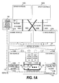
- FIG. 1A is a block diagram showing a hardware configuration of a computer system according to a first embodiment of this invention.
- the computer system of this embodiment includes a server system (0) 100A, a server system (1) 100B, a storage system 120, and a control terminal 150.
- server system In the server systems (0) 100A and (1) 100B, application programs (not shown) are operated.
- a parenthesized numeral such as (0) added after a name of a physical resource e.g., "server system”
- server system e.g., "server system”
- server system 100 In the description below, in the case of making description common to the server systems (0) 100A and (1) 100B, those server systems will be generically termed a server system 100.
- server system 100 In the case of making description common to the server systems (0) 100A and (1) 100B, those server systems will be generically termed a server system 100.
- identifiers of the physical resources and alphabets such as "A”.
- the I/O channels 160A, 160B, 160C, and 160D are fibre channels (FC).
- the I/O channels 160A, 160B, 160C, and 160D constitute a storage area network (SAN) for connecting one or more storage systems 120 with one or more server systems 100.
- the I/O channels 160A, 160B, 160C, and 160D are implemented by cables for interconnecting ports (not shown) of an I/O adaptor 106 and a channel adaptor 129. Referring to FIGS. 1B and 1C, the I/O adaptor 106 and the channel adaptor 129 will be described below.
- the physical disk drive 148 is a storage medium for storing data.
- this storage medium is a magnetic disk, but another type of medium such as an optical disk or a flash memory may be employed.
- a plurality of physical disk drives 148 may constitute redundant arrays of independent disks (RAID) so that redundancy can be added to the stored data. As a result, even when troubles occurs in some of the physical disk drives 148, the store data is not lost.
- the system power control units 146A and 146B control power supply to the physical resources in the storage system 120.
- the batteries 147A and 147B are backup power sources for the storage system 120. For example, when a power failure occurs, the batteries 147A and 147B supply power to the storage system 120.
- the server system (0) 100A is a computer which includes CPU's (0) and 101A and (1) 101B, a non-volatile memory (0) 102A, a main memory (0) 104A, a LAN adaptor (0) 105A, I/O adaptors (0) 106A and (1) 106B, and an I/O controller (0) 107A. Additionally, the server system (0) 100A includes a power control unit 108A for controlling power supply to each of the physical resources.
- the CPU's (0) 101A and (1) 101B execute operation regarding an operating system (OS) and an application program executed by the server system (0) 100A.
- OS operating system
- the server system (0) 100A shown in FIG. 1B includes two CPU's (0) 101A and (1) 101B.
- the server system (0) 100A may include only one CPU 101, or three or more CPU's 101.
- the main memory (0) 104A stores programs and data necessary for operating the CPU's (0) 101A and (1) 101B.
- the I/O controller (0) 107A interconnects the CPU's (0) 101A and (1) 101B, the non-volatile memory (0) 102A, the main memory (0) 104A, the LAN adaptor (0) 105A, and the I/O adaptors (0) 106A and (1) 106B to transfer data and a control signal.
- the I/O adaptors (0) 106A and (1) 106B are connected to the storage system 120 respectively via the I/O channels 160A and 160B.
- the I/O adaptors (0) 106A and (1) 106B transmit data input/output requests to the storage system 120 and receive data stored in the storage system 120.
- FIG. 1B shows the two I/O adaptors 106 for each server system 100. However, each server system 100 may include more I / O adaptors 106.
- a virtualization engine may be started and a hypervisor may be configured by the OS and the virtualization engine.
- the OS started when the power is turned on for the server system (0) 100A reads the virtualization engine to execute it.
- This virtualization engine may be stored in the non-volatile memory 102A or the storage system 120.
- the hypervisor 103A may be constituted of not software but hardware.
- the server system (0) 100A may include a hypervisor dedicated chip, or the CPU 101 may include a hypervisor unit for managing a virtual machine.
- the CPU's (4) 122A and (5) 122B execute operation regarding various management programs executed by the storage system 120.
- the LAN adaptor (2) 127A is connected to the server system 100, the control terminal 150, the disk board 132, and the other channel board 121 via the network 170.
- the LAN adaptor (2) 127A transfers a control signal and management information with the devices connected via the network 170.
- the internal network adaptor (0) 128A is connected to the disk board 132, the disk cache board 142, and the other channel board 121 via the internal network 131.
- the internal network adaptor (0) 128A transfers data or the like with each unit connected via the internal network 131.
- CPU's (6) 122C and (7) 122D, a power control unit 123B, a main memory (3) 124B, a non-volatile memory (3) 125B, a LAN adaptor (3) 127B, an internal network adaptor (1) 128B, channel adaptors (2) 129C and (3) 129D, and an I/O controller (3) 130B correspond to the CPU's (4) 122A and (5) 122B, the power control unit 123A, the main memory (2) 124A, the non-volatile memory (2) 125A, the LAN adaptor (2) 127A, the internal network adaptor (0) 128A, the channel adaptors (0) 129A and (1) 129B, and the I/O controller (2) 130A, respectively.
- the CPU's (8) 133A and (9) 133B execute operation regarding various programs executed in the storage system 120.
- the main memory (4) 135A stores programs and data necessary for operating the CPU's (8) 133A and (9) 133B.
- the storage hypervisor 137A is implemented by a management program for constituting logical partitions of the storage system 120 and generating a virtual storage system which is operated independently. To implement the storage hypervisor 137A, various methods can be employed as in the case of the hypervisor 103A of the server system (0) 100A.
- the I/O adaptor (4) 139A is connected to the physical disk drive 148.
- the I/O adaptor (4) 139A transmits a data input/output request to the physical disk drive 148 and receive data stored in the physical disk drive 148.
- the I/O controller (4) 141A interconnects the CPU's (8) 133A and (9) 133B, the main memory (4) 135A, the non-volatile memory (4) 136A, the LAN adaptor (4) 138A, the I/O adaptor (4) 139A, and the internal network adaptor (2) 140A to transfer data and a control signal.
- a CPU (10) 133C, a CPU (11) 133D, a power control unit 134B, a main memory (5) 135B, a non-volatile memory (5) 136B, a LAN adaptor (5) 138B, an I/O adaptor (5) 139B, an internal network adaptor (3) 140B, and an I/O controller (5) 141B correspond to the CPU's (8) 133A and (9) 133B, the power control unit 134A, the main memory (4) 135A, the non-volatile memory (4) 136A, the LAN adaptor (4) 138A, the I/O adaptor (4) 139A, the internal network adaptor (2) 140A, and the I/O controller (4) 141A, respectively.
- FIG. 2 is an explanatory diagram of a power supply system of the server system 100 according to the first embodiment of this invention.
- the system power switch 202 switches inputting (i.e., start of power supplying) and cutting-off (i.e., end of power supplying) of power supplied from the AC power source 201 to the sever system 100.
- cutting-off i.e., end of power supplying
- the power supply system of the server system 100 is divided into two areas, i.e., a standby power supply area 204 and a main power supply area 205.
- the power control unit 108 and the LAN adaptor 105 belong to the standby power supply area 204, while the CPUs 101, the I/O controller 107, the main memory 104, the non-volatile memory 102, and the I/O adaptors 106 belong to the main power supply area 205.
- power supplied to the main power supply area 205 is controlled by the power control unit 108.
- the power control unit 108 controls inputting and cutting of power to the physical resources belonging to the main power supply area 205.
- the power control unit 108 can control power supply to the physical resources in response to a request which the LAN adaptor 105 receives via the network 170. For example, upon reception of a request of supplying power to the main power supply area 205, the LAN adaptor 105 transmits a main power on interruption signal 203 to the power control unit 108. The power control unit 108 that has received the main power on interruption signal 203 supplies power to the main power supply area 205. Alternatively, the CPU 101 can instruct the power control unit 108 to turn on/off power to the resources such as the I/O adaptor 106.
- FIG. 3 is an explanatory diagram of a power supply system of the storage system 120 according to the first embodiment of this invention.
- Each of the AC power sources 301A and 301B are sources of power supplied to the storage system 120. As in the case of the AC power source 201 of FIG. 2, the AC power sources 301A and 301B may be any types of AC power sources.
- the system power switches 302A and 302B are similar to the system power switch 202 of FIG. 2.
- the system power control units 146A and 146B, the batteries 147A and 147B, and the physical resources are as described above referring to FIG. 1A, and thus description thereof will be omitted.
- the channel board 121A and the disk board 132A can instruct the power control units 146A and 146B to turn on/off power to the resources such as the disk caches 144 and 148.
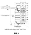
- FIG. 4 is an explanatory diagram of a power supply system of the channel board 121 of the storage system 120 according to the first embodiment of this invention.
- the power supply system of the channel board 121 includes a power control unit 123 and physical resources (i.e., CPU 122, I/O controller 130, main memory 124, non-volatile memory 125, channel adaptor 129, internal network adaptor 128, and LAN adaptor 127) for receiving power supply.
- physical resources i.e., CPU 122, I/O controller 130, main memory 124, non-volatile memory 125, channel adaptor 129, internal network adaptor 128, and LAN adaptor 127) for receiving power supply.
- the power supply system of the channel board 121 is divided into two areas, i.e., a standby power supply area 402 and a main power supply area 403.
- the power control unit 123 and the LAN adaptor 127 belong to the standby power supply area 402, while the CPUs 122, the I/O controller 130, the main memory 124, the non-volatile memory 125, the channel adaptors 129, and the internal network adaptor 128 belong to the main power supply area 403.
- power supplied to the standby power supply area 402 is not cut off by the power control unit 123.
- power is supplied to the standby power supply area 402 as longs as power is supplied from at least one of the system power control units 146A and 146B.
- the power control unit 123 can control power supply to the physical resources in response to a request which the LAN adaptor 127 receives via the network 170. For example, upon reception of a request of supplying power to the main power supply area 403, the LAN adaptor 127 transmits a main power on interruption signal 401 to the power control unit 123. The power control unit 123 that has received the main power on interruption signal 401 supplies power to the main power supply area 403. Alternatively, the CPU 122 can instruct the power control unit 123 to turn on/off power to the resources such as the I/O controller 130, the main memory 124, the non-volatile memory 125, the channel adaptor 129 and the internal network adaptor 128.
- the resources such as the I/O controller 130, the main memory 124, the non-volatile memory 125, the channel adaptor 129 and the internal network adaptor 128.
- the power supply system of the disk board 132 includes a power control unit 134 and physical resources (i.e., CPU 133, I/O controller 141, main memory 135, non-volatile memory 136, I/O adaptor 139, internal network adaptor 140, and LAN adaptor 138) for receiving power supply.
- physical resources i.e., CPU 133, I/O controller 141, main memory 135, non-volatile memory 136, I/O adaptor 139, internal network adaptor 140, and LAN adaptor 138
- the power control unit 134 Upon reception of power supplied from the system power control units 146A and 146B, the power control unit 134 controls supplying of power to the physical resources.
- the power supply system of the disk board 132 is divided into two areas, i.e., a standby power supply area 502 and a main power supply area 503.
- the power control unit 134 and the LAN adaptor 138 belong to the standby power supply area 502, while the CPUs 133, the I/O controller 141, the main memory 135, the non-volatile memory 136, the I/O adaptor 139, and the internal network adaptor 140 belong to the main power supply area 503.
- power supplied to the standby power supply area 502 is not cut off by the power control unit 134.
- power is supplied to the standby power supply area 502 as longs as power is supplied from at least one of the system power control units 146A and 146B.
- power supplied to the main power supply area 503 is controlled by the power control unit 134.
- the power control unit 134 controls inputting and cutting of power to the physical resources belonging to the main power supply area 503.
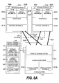
- the server system (0) 100A includes a physical layer, a hypervisor layer, and a virtual machine layer.
- the hypervisor layer is implemented by the hypervisor 103A.
- the server resources of the physical machine (0) 100A are managed by the hypervisor 103A.
- Bracketed numerals added after the physical resources are identifiers of the physical resources.
- Bracketed numerals added after virtual resources are identifiers of the virtual resources.
- the virtual machine layer includes virtual machines (0) 602A and (1) 602B. These virtual machines are generated by dividing server resources of the physical machine (0) 601A into logical partitions by the hypervisor 103A.
- OS's (0) 603A and (1) 603B operate in the virtual machines (0) 602A and (1) 602B.
- the OS (0) 603A executes operation by using server resources allocated to the virtual machine (0) 602A.
- the OS (1) 603B executes operation by using server resources allocated to the virtual machine (1) 602B.
- the server system (1) 100B has the same configuration as that of the server system (0) 100A.
- the explanation of the layers of the server system (0) 100A can be applied to a physical machine (1) 601B, a hypervisor 103B, virtual machines (2) 602C and (3) 602D, and OS's (2) 603C and (3) 603D of the server system (1) 100B.
- the physical layer of the storage system 120 is a physical storage system 611 which includes storage resources such as a physical disk drive, a CPU, a disk cache, a LAN adaptor, and a channel adaptor.
- the virtual storage layer includes virtual storage systems (0) 613A and (1) 613B. These virtual storage systems are generated by dividing storage resources of the physical storage system 611 into logical partitions by the storage hypervisor 612.
- FIGS. 6B and 6C the layers of the server system 100 and the storage system 120 will be described below in detail.
- the virtual machine control program 151 includes at least a storage resources control table 621 shown in FIG. 10, a virtual disk control table 622 shown in FIG. 8, a server resources control table 623 shown in FIG. 7, a server power control table 624 shown in FIG. 11, and a storage power control table 625 shown in FIG. 12. These tables will be described below in detail.
- FIG. 6B is a functional block diagram of the server system 100 according to the first embodiment of this invention.
- the physical machine (0) 601A of the server system (0) 100A includes physical resources of at least CPU's (0) 101A and (1) 101B, a main memory (0) 104A, a LAN adaptor (0) 105A, and I/O adaptors (0) 106A and (1) 106B. These are similar to those described above referring to FIG. 1B.
- the physical machine (0) 601A may further include other physical resources. However, as they are unnecessary for explanation of FIG. 6B, they are omitted.
- the hypervisor 103A includes a server power control table 651A, a virtual disk control table 652A, and a server resources control table 653A. These tables may respectively be similar to the server power control table 624, the virtual disk control table 622, and the server resources control table 623.
- the virtual machine (0) 602A includes virtual I/O adaptors (0) 654A and (1) 654B, CPU resources 655A, and memory resources 656A.
- the virtual machine (1) 602B includes virtual I/O adaptors (2) 654C and (3) 654D, CPU resources 655B, and memory resources 656B. These are virtual resources generated by dividing physical resources of the physical machine (0) 601A into logical partitions by the hypervisor 103A.
- a configuration of each layer of the server system (1) 100B is similar to that of the server system (0) 100A.
- the physical machine (1) 60 1 B includes physical resources of at least CPU's (2) 101C and (3) 101D, a main memory (1) 104B, a LAN adaptor (1) 105B, and I/O adaptors (2) 106C and (3) 106D.
- the hypervisor 103B includes a server power control table 651B, a virtual disk control table 652B, and a server resources control table 653B.
- the virtual machine (2) 602C includes virtual I/O adaptors (4) 654E and (5) 654F, CPU resources 655C, and memory resources 656C.
- the virtual machine (3) 602D includes virtual I/O adaptors (6) 654G and (7) 654H, CPU resources 655D, and memory resources 656D. These are virtual resources generated by dividing physical resources of the physical machine (1) 601B into logical partitions by the hypervisor 103B.
- FIG. 6C is a functional block diagram of the storage system 120 according to the first embodiment of this invention.
- the physical storage system 611 of the storage system 120 includes at least CPU's (4) 122A to (7) 122D, CPU's (8) 133A to (11) 133D, channel adaptors (0) 129A to (3) 129D, LAN adaptors (2) 127A, (3) 127B, (4) 138A, and (5) 138B, I/O adaptors (4) 139A and (5) 139B, disk cache boards (0) 142A and (1) 142B, and a physical disk drive 148. These are similar to those described above referring to FIGS. 1C to 1E.
- the physical storage system 611 may include other physical resources. However, as they are unnecessary for explanation of FIG. 6C, they are omitted.
- the storage hypervisor 612 includes at least a virtual disk control table 661, a disk address translation table 662, a storage resources control table 663, a storage power control table 664, and one or more virtual disks 665.
- the virtual disk control table 661, the storage resources control table 663, and the storage power control table 664 may respectively be similar to the virtual disk control table 622, the storage resources control table 621, and the storage power control table 625 managed by the control terminal 150.
- the control terminal 150 may collect pieces of information held in the tables of the storage hypervisor 612, and may hold the collected pieces of information in the tables of the control terminal 150.
- the virtual disk 665 is generated by dividing storage resources of the physical storage system 611 into logical partitions by the storage hypervisor 612.
- the virtual storage system (0) 613A includes at least virtual channel adaptors (0) 666A and (1) 666B, disk cache resources 667A, CPU resources 668A, internal network resources 669A, and one or more logical units 670.
- the virtual storage system (1) 613B includes at least virtual channel adaptors (2) 666C and (3) 666D, disk cache resources 667B, CPU resources 668B, internal network resources 669B, and one or more logical units 670. These are virtual resources generated by dividing physical resources of the physical storage system 611 into logical partitions by the storage hypervisor 612.
- the logical unit 670 is a logical storage area provided to the server system 100.
- the OS 603 of the server system 100 recognizes each logical unit 670 as one disk.
- the logical unit 670 is correlated with the virtual disk 665.
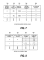
- FIG. 7 is an explanatory diagram of the server resources control table 623 according to the first embodiment of this invention.
- the server resources control table 623 holds information for controlling allocation of physical resources to virtual resources of the server system 100.
- the server resources control table 623 includes five columns of a virtual machine number 701, a CPU utilization rate 702, a memory capacity 703, a virtual I/O adaptor number 704, and I/O adaptor number 705.
- An identifier (i.e., parenthesized numeral in FIG. 6A) of the virtual machine 602 is registered in the virtual machine number 701.
- the CPU utilization rate 702 and the memory capacity 703 respectively indicate CPU resources 655 and memory resources 656 allocated to each virtual machine 602. For example, in FIG. 7, "20%” and "512 MB" are respectively registered as the CPU utilization rate 702 and the memory capacity 703 corresponding to a value "0" of the virtual machine number 701. This means that 20% of the CPU's (0) 101A and (1) 101B among the physical resources of the physical machine (0) 601A is allocated as the CPU resources 655A of the virtual machine (0) 602A, and a storage area of 512 megabytes (MB) of the main memory 104A is allocated as the memory resources 656A.
- MB 512 megabytes
- An identifier of the virtual I/O adaptor 654 included in each virtual machine 602 is registered in the virtual I/O adaptor number 704.
- An identifier of the I/O adaptor 106 allocated to each virtual I/O adaptor 654 is registered in the I/O adaptor 705.
- I/O adaptors 106 are registered as I/O adaptors 106 corresponding to values "0", “1", “2", and “3" of the virtual I/O adaptor number 704, respectively.
- the I/O adaptor (0) 106A is allocated to the virtual I/O adaptors (0) 654A and (2) 654C
- the I/O adaptor (1) 106B is allocated to the virtual I/O adaptors (1) 654B and (3) 654D. Accordingly, by allocating one physical resource to a plurality of virtual resources, it is possible to provide more virtual resources than physical resources.
- the server resources control table 653 of each server system 100 holds information similar to that shown in FIG. 7. However, the server resources control table 653 may hold information only regarding the virtual machine 602 included in the sever system 100 which holds the table. For example, the server resources control table 653A of the server system (0) 100A may hold information only regarding the virtual machines (0) 602A and (1) 602B.
- FIG. 8 is an explanatory diagram of the virtual disk control table 622 according to the first embodiment of this invention.
- the virtual disk control table 622 holds information for controlling allocation of a virtual disk 665 to the virtual machine 602.
- the virtual disk control table 622 includes four columns of a virtual machine number 801, a virtual storage number 802, a logical unit number 803, and a virtual disk number 804.
- An identifier of the virtual machine 602 is registered in the virtual machine number 801 as in the case of the virtual machine number 701 of FIG. 7.
- An identifier of the virtual disk 665 allocated to the virtual machine 602 is registered in the virtual disk number 804.
- the three logical units 670 of the virtual storage system (0) 613A are allocated to the virtual machine (0) 602A. Identifiers of these logical units 670 are respectively "0", “1” and “2". The logical units 670 are correlated with the virtual disks 665 respectively having identifiers "121", "122”, and "123".
- one virtual storage system 613 is allocated to one virtual machine 602.
- a plurality of virtual machines 602 may share one virtual storage system 613.
- a plurality of values (identifiers) are registered as virtual storage numbers 802 corresponding to a value of one virtual machine number 801.
- the virtual disk control table 622 holds information for managing allocation of the virtual disk 665 regarding all the virtual machines 602 in the computer system.
- the virtual disk control table 652 of each server system 100 also holds information similar to that shown in FIG. 8. However, the virtual disk control table 652 may hold information only regarding the virtual machine 602 included in the sever system 100 which holds the table. For example, the virtual disk control table 652A of the server system (0) 100A may hold information only regarding the virtual disks 665 allocated to the virtual machines (0) 602A and (1) 602B.
- FIG. 9 is an explanatory diagram of the disk address translation table 662 according to the first embodiment of this invention.
- the disk address translation table 662 includes four columns of a virtual disk number 901, a virtual block address 902, a physical disk number 903, and a physical block address 904.
- An identifier of the physical disk drive 148 allocated to the virtual disk 665 is registered in the physical disk number 903.
- a physical block address for uniquely, in each physical disk drive 148, identifying a logical block of the physical disk drive 148 allocated to the virtual disk 665 is registered in the physical block address 904.
- the logical block is an area of a predetermined size treated as a management unit of a storage area. For example, when SCSI Standard is applied, the logical block is a storage area of 512 bytes.
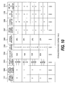
- FIG. 10 is an explanatory diagram of the storage resources control table 621 according to the first embodiment of this invention.
- the storage resources control table 621 includes ten columns of a virtual machine number 1001, a virtual storage system number 1002, a virtual disk number 1003, a disk cache capacity 1004, a CPU 1005 in charge, an internal bandwidth 1006, a virtual channel adaptor 1007, a channel adaptor 1008, an I/O adaptor 1009, and a virtual I/O adaptor 1010.
- the virtual machine number 1001, the virtual storage system number 1002, and the virtual disk number 1003 are respectively similar to the virtual machine number 801, the virtual storage number 802, and the virtual disk number 804 of FIG. 8, and thus description thereof will be omitted.
- a capacity of the disk cache 144 allocated as a disk cache resource 667 of each virtual storage system 613 is registered in the disk cache capacity 1004.
- a bandwidth of the internal network 131 allocated as an internal network resource 669 included in each virtual storage system 613 is registered in the internal bandwidth 1006.
- An identifier of the virtual channel adaptor 666 included in each virtual storage system 613 is registered in the virtual channel adaptor 1007.
- An identifier of the channel adaptor 129 allocated as a virtual channel adaptor 666 of each virtual storage system 613 is registered in the channel adaptor 1008.
- An identifier of the virtual I/O adaptor included in each virtual storage system 613 is registered in the virtual I/O adaptor 1010.
- An identifier of the I/O adaptor 139 allocated as a virtual I/O adaptor of each virtual storage system 613 is registered in the I/O adaptor 1009.
- the storage resources control table 663 of the storage system 120 also holds information similar to that shown in FIG. 10. However, when the computer system includes a plurality of storage systems 120, the storage resources control table 663 of each storage system 120 may hold information only regarding the storage system 120. In this case, the storage resources control table 621 may hold information regarding all the storage systems collected from all the storage systems 120 of the computer system.
- FIG. 11 is an explanatory diagram of the server power control table 624 according to the first embodiment of this invention.
- the server power control table 624 holds information for controlling a power state of each resource of the server system 100.
- the resource classification 1101 indicates that each resource registered in the server power control table 624 is a physical or virtual resource.
- a value "P" of the resource classification 1101 indicates a physical resource, and a value "V” indicates a virtual resource.
- Names and identifiers of physical and virtual resources included in the server system 100 are registered in the resource 1102.
- the server power control table 624 holds information for managing power states of resources included in all the server systems 100 of the computer system.
- FIG. 12 is an explanatory diagram of the storage power control table 625 according to the first embodiment of this invention.
- the storage power control table 625 holds information for controlling a power state of each resource of the storage system 120.
- the storage power control table 625 includes four columns of a resource classification 1201, a resource 1202, a power state 1203, and a used virtual machine number 1204.
- Names and identifiers of physical and virtual resources included in the storage system 120 are registered in the resource 1202.
- An identifier of the virtual storage system 613 using each physical resource i.e., virtual storage system 613 to which each physical resource is allocated
- “none (n/a)” is set in the used virtual storage system number 1204 corresponding to the virtual resource.
- the storage power control table 664 of the storage system 120 also holds information similar to that shown in FIG. 12. However, when the computer system includes a plurality of storage systems 120, the storage power control table 664 of each storage system 120 may hold information only regarding the storage system 120.
- the user operates the control terminal 150 to set physical resources to be allocated to the virtual machine 602 and the virtual storage system 613 (1301).
- the control terminal 150 transmits contents set for the virtual machine 602 in Step 1301 to the server system 100 (1302).
- the hypervisor 103 of the server system 100 generates a virtual machine 602 according to the setting transmitted from the control terminal 150 (1303).
- the server system 100 reports setting completion to the control terminal 150 (1304).
- control terminal 150 transmits contents set for the virtual storage system 613 in Step 1301 to the storage system 120 (1305).
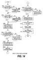
- FIG. 14 is a flowchart of boot processing of the virtual machine 602 executed according to the first embodiment of this invention.
- the user determines whether the system power switch 302 of the storage system 120 has been turned on (1401).
- Step 1401 If it is determined in Step 1401 that the system power switch 302 has been turned on, the process proceeds to Step 1403. On the other hand, if it is determined in Step 1401 that the system power switch 302 has not been turned on (i.e., power has been cut), the user turns on the system power switch 302 (1402).
- the console terminal is a computer connected to each server system 100 to operate each server system 100.
- the control terminal 150 is used as a console terminal.
- the control terminal 150 determines whether the CPU 122 or the like allocated to the virtual machine 602 to be booted among the CPU 122 and the like of the storage system 120 has been turned on (1406). For this determination, the storage power control table 625 is referred to.
- the CPU 122 or the like i.e., the CPU 122 or the CPU 133 allocated to the virtual machine 602 to be booted is described as a relevant CPU 122 or the like.
- the allocation of the CPU 122 or the like is set by processing shown in FIG. 13.
- Step 1406 If it is determined in Step 1406 that the relevant CPU 122 or the like has been turned on, the process proceeds to Step 1408. On the other hand, if it is determined in Step 1406 that the relevant CPU 122 or the like has not been turned on, the control terminal 150 transmits an instruction to turn on the relevant CPU 122 or the like to the storage system 120 (1407). This instruction reaches the LAN adaptors 127 and 138 of the storage system 120 via the network 170. Alternatively, the following method may be employed. When the system power is turned on, at least one CPU 122 is operated. The CPU 122 executes the storage hypervisor 137, the control terminal 150 transmits a booting command of the relevant CPU to the CPU 122, and the storage hypervisor 137 boots the relevant CPU 122.
- the control terminal 150 determines whether the CPU 101 allocated to the virtual machine 602 to be booted among the CPU's 101 of the server system 100 has been turned on (1410). For this determination, the server power control table 624 is referred to.
- the CPU 101 allocated to the virtual machine 602 to be booted is described as a relevant CPU 101.
- the allocation of the CPU 101 is set by the processing shown in FIG. 13.
- control terminal 150 creates a storage resources control table 621 based on contents set in FIG. 13 and contents detected in Step 1414 (1415).
- FIG. 15 is a flowchart of processing executed at the time of cable connection according to the first embodiment of this invention.
- FIG. 15 The processing of FIG. 15 is executed in each server system 100 and the storage system 120.
- execution by the server 100 is taken as an example, but the storage system 120 executes similar processing.
- any physical address may be used for exchanging in Step 1502 as long as a port to connect the cable is uniquely specified.
- the physical address may be a world wide name (WWN).
- WWN world wide name
- the physical address may be a MAC address.
- the I/O adaptor 106 notifies the physical address obtained by the exchanging to the hypervisor 103.
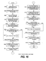
- FIG. 16 is a flowchart of shutdown processing of the virtual machine 602 executed according to the first embodiment of this invention.
- FIG. 16 The processing of FIG. 16 is executed when the user powers off one of the virtual machines 602.
- the virtual machine 602 which is to be powered off by the user is described as a relevant virtual machine 602.
- the user operates the control terminal 150 to instruct shutting-down to the OS 603 operating on the relevant virtual machine 602 (1601).
- the OS 603 cuts off power of the relevant virtual machine 602 (1603). However, at this time, the OS 603 only issues a command of cutting of power. In reality, the power has not been cut off.
- the hypervisor 103 executes loop processing (1605 to 1608) for each resource specified in Step 1604.
- each resource specified in Step 1604 is described as a relevant resource.
- the hypervisor 103 determines whether the relevant resource is used by the other virtual machine 602. In other words, the hypervisor 103 determines whether the relevant resource has also been allocated to the virtual machine 602 other than the relevant virtual machine 602. Specifically, the hypervisor 103 refers to the server power control table 651 to determine whether a used virtual machine number 1104 of an entry corresponding to the relevant resource includes an identifier other than that of the relevant virtual machine 602.
- the hypervisor 103 refers to an entry where a resource 1102 is "CPU (0)" in the server power control table 651 to determine whether the used virtual machine number 1104 of the entry includes a value other than "0". If the server power control table 651 is as shown in FIG. 11, the used virtual machine number 1104 corresponding to the CPU (0) includes both "0" and "1". In this case, the CPU (0) 101A is also used by the virtual machine (1) 602B. Accordingly, in Step 1606, it is determined that the relevant resource has also been allocated to the virtual machine 602 in addition to the relevant virtual machine 602 (YES).
- Step 1606 if it is determined in Step 1606 that the relevant resource has not been allocated to the virtual machine in addition to the relevant virtual machine 602, after the relevant virtual machine 602 shuts down, the relevant resource is not used by any virtual machines 602. Thus, the hypervisor 103 cuts off power of the relevant resource (1607). In other words, the hypervisor 103 instructs to cut off power to the power control unit 108, and the power control unit 108 cuts off power of the relevant resource.
- the hypervisor 103 reports the cutting of the power of the resources to the control terminal 150 (1609).
- control terminal 150 updates the server power control table 624 (1610). Further, to reflect the reported cutting of power, the hypervisor 103 updates the server power control table 651.
- control terminal 150 refers to the storage resources control table 621 to instruct to cut off power to the virtual storage system 613 allocated to the relevant virtual machine 602 (1611). At this time, the control terminal 150 specifies a virtual storage system 613 allocated to the relevant virtual machine 602. The virtual storage system 613 which is to be powered off by that instruction is described as a relevant virtual storage system 613 in the explanation of FIG. 16.
- the storage hypervisor 612 specifies resources allocated to the relevant virtual storage system 613 (1612).
- the storage hypervisor 612 refers to the virtual disk control table 661, the disk address translation table 662, and the storage resources control table 663.
- a physical disk drive 148 allocated to the relevant virtual storage system 613 can be specified.
- CPU's 122 and 133, a channel adaptor 129, and an I/O adaptor 139 that are allocated to the relevant virtual storage system 613 can be specified.
- the storage hypervisor 612 executes loop processing (1613 to 1616) for each resource specified in Step 1612.
- each resource specified in Step 1612 is described as a relevant resource.
- Step 1614 the storage hypervisor 612 determines whether the relevant resource has also been allocated to the virtual storage system 613 other than the relevant virtual storage system 613. This determination is executed by the same method as that shown in Step 1606. Specifically, the storage hypervisor 612 refers to the storage power control table 664 to determine whether a used virtual storage system number 1204 of an entry corresponding to the relevant resource includes an identifier other than that of the relevant virtual storage system 613.
- the relevant virtual storage system 613 is a virtual storage system (0) 613A and the relevant resource is a CPU (4) 122A
- the relevant resource is a CPU (4) 122A
- the resource 1202 and the used virtual storage system number 1204 of FIG. 10 it is determined that the CPU (4) 122A is used by both the virtual storage system (0) 613A and the virtual storage system (2) (not shown).
- Step 1614 If it is determined in Step 1614 that the relevant resource has been allocated to the virtual storage system 613 in addition to the relevant virtual storage system 613, the relevant resource is still used by one of the virtual storage systems 613. Accordingly, the power of the relevant resource cannot be cut off. In this case, the process proceeds to Step 1616 without cutting off the power of the relevant resource.
- Step 1614 if it is determined in Step 1614 that the relevant resource has not been allocated to the virtual storage system 613 other than the relevant virtual storage system 613, after the relevant virtual storage system 613 stops, the relevant resource is not used by any virtual storage systems 613.
- the storage hypervisor 612 cuts off power of the relevant resource (1615).
- the storage hypervisor 137 instructs to cut off power to the power control units 123 and 134, and the power control unit 123 and 134 cuts off power of the relevant resource.
- the storage hypervisor 612 reports the cutting of the power of the resources to the control terminal 150 (1617).
- control terminal 150 updates the storage power control table 625 (1618). Further, to reflect the reported cutting of power, the storage hypervisor 612 updates the storage power control table 664.
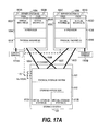
- FIG. 17A is a functional block diagram of a computer system according to the second embodiment of this invention.
- control terminal 150 holds the information for controlling the entire computer system, and controls the entire computer system.
- one of server systems 100 holds information for controlling the entire computer system, and controls the entire computer system.
- the computer system of the second embodiment includes no control terminal 150 unlike the first embodiment.
- console terminals 1701A and 1701B are respectively connected to the server systems (0) 100A and (1) 100B.
- the console terminal 1701 is a computer for operating each server system 100.
- a storage system 120, an I/O channel 160, and a network 170 of the second embodiment are similar to those of the first embodiment, and thus description thereof will be omitted.
- the server system 100 of the second embodiment is similar to that of the first embodiment except for tables and programs included in a hypervisor 103.
- the hypervisor 103 of the second embodiment includes a server power control table 1702, a virtual disk control table 1703, a server resources control table 1704, a storage resources control table 1705, a storage power control table 1706, and a virtual machine control program 1707.
- the server power control table 1702, the virtual disk control table 1703, the server resources control table 1704, the storage resources control table 1705, and the storage power control table 1706 hold information for controlling the entire computer system.
- These tables are respectively similar to the server power control table 624, the virtual disk control table 622, the server resources control table 623, the storage resources control table 621, and the storage power control table 625 of the first embodiment, and thus description thereof will be omitted.
- one of the server systems (0) 100A and (1) 100B may include a hypervisor 103 which includes a server power control table 651, a virtual disk control table 652, and a server resources control table 653. This is because at least one of a plurality of server systems 100 needs to control the computer system. To increase fault tolerance of the computer system, however, as shown in FIG. 17B, the plurality of server systems 100 preferably hold information for controlling the entire computer system.
- a hardware configuration of the computer system of the second embodiment is similar to that of the computer system of the first embodiment except for the console terminal 1701 disposed in place of the control terminal 150 as shown in FIGS. 1A, 1B, 1C, 1D, and 1E. Thus, description of the hardware configuration of the computer system of the second embodiment will be omitted.
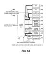
- FIG. 18 is an explanatory diagram of a power supply system of a channel board 121 of the storage system 120 according to the second embodiment of this invention.
- the power supply system of the channel board 121 of the storage system 120 of the second embodiment is almost similar to that of the first embodiment as shown in FIG. 4. However, a boundary between a main power supply area and a standby power supply area is different. Hereinafter, only differences of FIG. 18 from FIG. 4 will be described.
- the channel adaptor 129 When the instruction of power-on is transmitted via the I/O channel 160, the channel adaptor 129 must belong to the standby power supply area 1802 so that the instruction of power-on can be received while the power of the main power supply area 1803 is cut-off. Upon reception of the instruction of power-on, the channel adaptor 129 transmits a main power-on interruption signal 1801 to the power control unit 123.
- the main power-on interruption signal 1801 is a signal similar to the main power-on interruption signal 401.
- FIG. 19 is a flowchart of resource allocation setting processing executed according to the second embodiment of this invention.
- the resource allocation setting processing executed according to the second embodiment is similar to that executed according to the first embodiment shown in FIG. 13 except for some Steps. Differences of the processing of FIG. 19 from the processing of FIG. 13 will be described.
- Steps 1901 to 1903 of FIG. 19 respectively correspond to Steps 1301 to 1303 of FIG. 13.
- Steps 1904 to 1906 of FIG. 19 respectively correspond to Steps 1305 to 1307 of FIG. 13.
- the computer system of the second embodiment includes no control terminal 150. Accordingly, in Step 1901, the user operates the console terminal 1701 to set physical resources to be allocated to the virtual machine 602 and the virtual storage system 613. In Step 1902, the console terminal 1701 transmits set contents to the server system 100. In Step 1904, the server system 100 transmits contents set for the virtual storage system 613 to the storage system 120. In Step 1906, the storage system 120 reports setting completion to the server system 100.
- FIG. 20 is a flowchart of boot processing of the virtual machine 602 executed according to the second embodiment of this invention.
- Steps 2001 to 2004 are similar to that of Steps 1401 to 1404 of FIG. 14. Thus, description of these Steps will be omitted.
- Step 2005 the user operates the console terminal 1701 to instruct booting of the virtual machine 602.
- a hypervisor 103 determines whether power of a CPU 101 (in the explanation of FIG. 20, described as relevant CPU 101) allocated to the virtual machine 602 to be booted among CPU's 101 of the server system has been turned on (2006). For this determination, a server power control table 1702 is referred to. The allocation of the CPU 101 is set by processing shown in FIG. 19.
- Step 2006 If it is determined in Step 2006 that the relevant CPU 101 has been turned on, the process proceeds to Step 2008. On the other hand, if it is determined in Step 2006 that the relevant CPU 101 has not been turned on, the hypervisor 103 issues an instruction of power-on of the relevant CPU 101 to the relevant CPU 101 (2007).
- the server system 100 executes initial setting processing of the server system 100 (2009).
- the hypervisor 103 determines whether the CPU 122 or the like (in the explanation of FIG. 20, described as relevant CPU 122 or the like) allocated to the virtual machine 602 to be booted among the CPU's 122 and 133 of the storage system 120 has been turned on (2010). For this determination, the storage power control table 1706 is referred to.
- the allocation of the CPU 122 or the like is set by processing shown in FIG. 19.
- Step 2010 If it is determined in Step 2010 that the relevant CPU 122 or the like has been turned on, the process proceeds to Step 2012. On the other hand, if it is determined in Step 2010 that the relevant CPU 122 or the like has not been turned on, the hypervisor 103 transmits an instruction of power-on of the relevant CPU 122 or the like to the storage system 120 (2011). This instruction reaches LAN adaptors 127 and 138 of the storage system 120 via the network 170.
- the storage system 120 executes initial setting processing of the storage system 120 (2013).
- the hypervisor 103 detects how a cable constituting the I/O channel 160 has been connected (2014). This processing may be executed by a method shown in FIG. 15. As a result, it is discovered which of the channel adaptors 129 are connected to which of the I / O adaptors 106 by the I/O channel 160.
- Step 2011, the instruction of power-on of the CPU 122 or the like is transmitted to the storage system 120 via the network 170. It is because data cannot be transmitted via the I/O channel 160 before the connection state of the cable is detected in Step 2014.
- the server system 100 can transmit the instruction of supplying/cutting of power to the storage system 120 via the I/O channel 160 (i.e., so-called in-band).
- FIG. 21 is a flowchart of shutdown processing of the virtual machine 602 executed according to the second embodiment of this invention.
- Steps 2102 to 2104 are respectively similar to Steps 1602 to 1604 of FIG. 16, and thus description thereof will be omitted.
- the hypervisor 103 executes loop processing (2105 to 2109) for each resource specified in Step 2104.
- each resource specified in Step 2104 is described as a relevant resource.
- Step 2106 If it is determined in Step 2106 that the relevant resource has been allocated to the virtual machine 602 in addition to the relevant virtual machine 602, the relevant resource is still used by one of the virtual machines 602. Accordingly, the power of the relevant resource cannot be cut off. In this case, the process proceeds to Step 2109 without cutting off the power of the relevant resource.
- Step 2106 if it is determined in Step 2106 that the relevant resource has not been allocated to the virtual machine 602 other than to the relevant virtual machine 602, after the relevant virtual machine 602 shuts down, the relevant resource is not used by any virtual machines 602. Thus, power of the relevant resource can be cut off.
- supplying/cutting of power of the server system 100 and the storage system 120 is controlled by the CPU 101 which executes the hypervisor 103 of the server system 100. Accordingly, when power of all the CPU's 101 of the server system 100 is cut off, it becomes impossible to turn on the CPU's 101 any more. Thus, when the relevant resource is the only currently operating CPU 101, the power thereof cannot be cut off.
- the hypervisor 103 determines whether the relevant resource is a CPU 101 and the number of currently operating CPU's 101 is one (2107).
- the hypervisor 103 updates the server power control table 1702 to reflect the cutting of the power (2110).
- the server system 100 instructs to cut off power to the virtual storage system 613 allocated to the relevant computer (2111).
- the virtual storage system 613 which is to be powered off in response to the instruction is described as a relevant virtual storage system 613 in the description of FIG. 21.
- the I/O channel 160 is a fibre channel
- a method in which a "logout" message of a fibre channel protocol is a power cutting-off instruction may be used.
- the virtual storage system 613 allocated to the relevant virtual machine 602 is specified by referring to the virtual machine number 1001 and the virtual storage system number 1002 of the storage resources control table 663 (or storage resources control table 1705).
- Steps 2112 to 2116 Processing of next Steps 2112 to 2116 is similar to that of Steps 1612 to 1616 of FIG. 16, and thus description thereof will be omitted.
- the storage hypervisor 612 reports the cutting of the power of the resources to the server system 100 (2117).
- the server system 100 updates the storage power control table 1706 (2118). Further, to reflect the reported cutting of power, the storage hypervisor 612 updates the storage power control table 664.
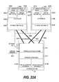
- FIG. 22A is a functional block diagram of a computer system according to the third embodiment of this invention.
- a server system 100, an I/O channel 160, and a network 170 of the third embodiment are similar to those of the first embodiment, and thus description thereof will be omitted.
- FIG. 22B is a functional block diagram of the storage system 120 according to the third embodiment of this invention.
- the storage system 120 of the third embodiment is similar to that of the first embodiment except for tables and programs included in a storage hypervisor 612.
- the storage hypervisor 612 of the third embodiment includes a virtual disk control table 2202, a disk address translation table 2203, a storage resources control table 2204, a server resources control table 2205, a storage power control table 2206, a server power control table 2207, a virtual machine control program 2208, and one or more virtual disks 665.
- the virtual disk control table 2202, the storage resources control table 2204, the server resources control table 2205, the storage power control table 2206, and the server power control table 2207 hold information for managing the entire computer system. These tables are respectively similar to the virtual disk control table 622, the storage resources control table 621, the server resources control table 623, the storage power control table 625, and the server power control table 624 of the first embodiment, and thus description thereof will be omitted.
- a hardware configuration of the computer system of the third embodiment is similar to that of the computer system of the first embodiment except for the console terminal 2201 disposed in place of the control terminal 150 shown in FIGS. 1A, 1B, 1C, 1D, and 1E. Thus, description of the hardware configuration of the computer system according to the third embodiment will be omitted.
- FIG. 23 is a flowchart of resource allocation setting processing executed according to the third embodiment of this invention.
- the resource allocation setting processing executed according to the third embodiment is similar to that executed according to the first embodiment shown in FIG. 13 except for some Steps. Detailed description of points of the processing of FIG. 23 similar to those of the processing of FIG. 13 will be omitted.
- Steps 2301 to 2306 of FIG. 23 respectively correspond to Steps 1301, 1305, 1306, 1302, 1303 and 1307 of FIG. 13.
- the computer system of the third embodiment includes no control terminal 150. Accordingly, in Step 2301, the user operates the console terminal 2201 to set physical resources to be allocated to the virtual machine 602 and the virtual storage system 613. In Step 2302, the console terminal 2201 transmits set contents to the storage system 120. In Step 2303, the storage system 120 generates a virtual storage system 613. In Step 2304, the storage system 120 transmits contents set for the virtual machine 602 to the server system 100. In Step 2305, the server system generates a virtual machine 602. In Step 2306, the server system 100 reports setting completion to the storage system 120.
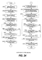
- FIG. 24 is a flowchart of shutdown processing of the virtual machine 602 executed according to the third embodiment of this invention.
- FIG. 24 The processing of FIG. 24 is executed when the user cuts off power of one of the virtual machines 602.
- the virtual machine 602 which is to be powered off by the user is described as a relevant virtual machine 602.
- the user operates the console terminal 2201 to instruct shutting-down to an OS 603 operating on the relevant virtual machine 602 (2401).
- the shutting-down instruction reaches the server system 100 via the storage system 120 and the network 170.
- Steps 2402 to 2408 are respectively similar to Steps 1602 to 1608 of FIG. 16, and thus description thereof will be omitted.
- the hypervisor 103 updates the server power control table 651 to reflect the cutting of the power (2409).
- the hypervisor 103 reports the executed cutting of power to the storage system 120 (2410).
- the storage system 120 updates the server power control table 2207 in response to the report.
- the storage system 120 instructs to cut off power to the virtual storage system 613 allocated to the relevant computer 602 (2411).
- the storage hypervisor 612 refers to the virtual machine number 1001 and the virtual storage number 1002 of the storage resources control table 2204 to specify a virtual storage system 613 allocated to the relevant computer 602.
- the virtual storage system 613 specified in Step 2411 is a virtual storage system 613 which is to be powered off by processing described below.
- the virtual storage system 613 specified in Step 2411 is described as a relevant virtual storage system 613 in the description of FIG. 24.
- the storage hypervisor 612 specifies resources allocated to the relevant virtual storage system 613 (2412). This processing is similar to that of Step 1612 of FIG. 16.
- the storage hypervisor 612 executes loop processing for the resources specified in Step 2412 (2413 to 2417).
- the resources specified in Step 2412 are described as relevant resources.
- Step 2414 the storage hypervisor 612 determines whether the relevant resource has also been allocated to the virtual storage system 613 in other than the relevant storage system 613. This determination is executed by the same method as that of Step 1614.
- Step 2414 if it is determined in Step 2414 that the relevant resource has not been allocated to the virtual storage system 613 other than the relevant virtual storage system 613, after the relevant virtual storage system 613 shuts down, the relevant resource is not used by any virtual storage systems 613. Thus, power of the relevant resource can be cut off.
- supplying/cutting of power of the server system 100 and the storage system 120 is controlled by a CPU 122 or the like which executes the storage hypervisor 612 of the storage system 120. Accordingly, when power of all the CPU's 122 or the like of the storage system 120 is cut off, it becomes impossible to turn on the CPU's or the like any more. Thus, when the relevant resource is the only currently operating CPU 122 or the like, the power thereof cannot be cut off.
- the storage hypervisor 612 determines that the relevant resource is a CPU 122 or 133, and whether the number of currently operating CPU's 122 or the like is one (2415).
- Step 2415 If it is determined in Step 2415 that the relevant resource is a CPU 122 or 133, and the number of currently operating CPU's 122 or the like is 1, the relevant resource is the only currently operating CPU 122 or the like. In this case, the process proceeds to Step 2417 without cutting off power of the resource.
- Step 2415 If it is determined in Step 2415 that the relevant resource is neither a CPU 122 nor 133, or that the number of currently operating CPU's 122 or the like is not 1, the relevant resource is not the only currently operating CPU 122 or the like. In this case, the storage hypervisor 612 cuts off power of the relevant resource (2416).
- the storage hypervisor 612 updates the storage power control table 2206 to reflect the cutting of the power (2418) .
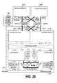
- FIG. 25 is a block diagram showing a hardware configuration of the computer system according to the fourth embodiment of this invention.
- An I/O channel 160A connects an I/O adaptor (0) 106A with an I/O channel switch (0) 2501A.
- An I/O channel 160B connects an I/O adaptor (1) 106B with an I/O channel switch (1) 2501B.
- An I/O channel 160C connects an I/O adaptor (2) 106C with the I/O channel switch (0) 2501A.
- An I/O channel 160D connects an I/O adaptor (3) 106D with the I/O channel switch (1) 2501B.
- An I/O channel 160E connects the I/O channel switch (0) 2501A with a channel adaptor (0) 129A.
- An I/O channel 160F connects the I/O channel switch (0) 2501A with a channel adaptor (2) 129C.
- An I/O channel 160G connects the I/O channel switch (1) 2501B with a channel adaptor (1) 129B.
- An I/O channel 160H connects the I/O channel switch (1) 2501B with a channel adaptor (3) 129D.
- the I/O channel switches (0) 2501A and (1) 2501B are connected to a control terminal 150 via a network 170.
- a functional block diagram of the fourth embodiment is similar to that of the first embodiment except for interconnection between the server system 100 and the storage system 120 via the I/O channel 160 and the I/O channel switch 2501.
- a power supply system of each apparatus of the fourth embodiment, tables held by the apparatus, and processing executed by the apparatus are similar to those of the first embodiment except for those described below. Description of components of the fourth embodiment similar to those of the first embodiment will be omitted.
- FIG. 26 is a block diagram showing a hardware configuration of the I/O channel switch 2501 according to the fourth embodiment of this invention.
- the I/O channel switch 2501 includes a power control unit 2601, a switch control unit 2602, a LAN adaptor (6) 2604, a crossbar switch 2605, and a plurality of ports 2606.
- the power control unit 2601 controls power supply to each physical resource in the I/O channel switch 2501.
- the switch control unit 2602 controls connection between the ports 2606 by the crossbar switch 2605. Specifically, the switch control unit 2602 stets a combination of ports 2606 to permit/inhibit communication. The switch control unit 2602 holds information indicating the set combination of the ports 2606 as a routing table 2603.
- the LAN adaptor (6) 2604 is an interface for communication with an apparatus such as the control terminal 150 via the network 170.
- the crossbar switch 2605 switches connection between the ports 2606. Specifically, the crossbar switch 2605 permits/inhibits communication between the ports 2606 according to setting of the switch control unit 2602.
- Each port 2606 is connected to the I/O channel 160, and communicates with the server system 100 or the storage system 120 via the I/O channel 160.
- FIG. 26 shows four ports 2606A, 2606B, 2606C and 2606D.
- the I/O channel switch 2501 may include more ports 2606.
- FIG. 27 is an explanatory diagram of a power supply system of the I/O channel switch 2501 according to the fourth embodiment of this invention.
- the power supply system of the I/O channel switch 2501 includes an AC power source 2701, a system power switch 2702, a power control unit 2601, and physical resources (i.e., each port 2606, crossbar switch 2605, switch control unit 2602, and LAN adaptor 2604) for receiving power supplies.
- the AC power source 2701 is a source of power supplied to the I/O channel switch 2501.
- the AC power source 2701 may be any types of AC power source as in the case of the AC power source 201 shown in FIG. 2.
- the system power switch 2702 is a switch similar to the system power switch 202 of FIG. 2.
- the power control unit 2601 receives power supplied from the AC power source 2701 via the system power switch 2702 and controls supplying of the power to each physical resource.
- the power supply system of the I/O channel switch 2501 is not divided into a plurality of power supply areas as shown in FIG. 2.
- the power control unit 2601 can control supplying/cutting of power for each port 2606.
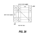
- FIG. 28 is an explanatory diagram of a routing table 2603 held by the I/O channel switch 2501 according to the fourth embodiment of this invention.
- the routing table 2603 includes an input port number 2801, an output port number 2802, and information indicating communication permission between the ports 2606.
- the input port number 2801 and output port number 2802 are identifiers assigned to the ports 2606.
- the information indicating communication permission is represented by "o" when communication is permitted, and " ⁇ " when communication is inhibited.
- a virtual machine number 1001, a virtual storage system number 1002, a virtual disk number 1003, a disk cache capacity 1004, a CPU 1005 in charge, the internal bandwidth 1006, a virtual channel adaptor 1007, a channel adaptor 1008, an I/O adaptor 1009, and a virtual I/O adaptor 1010 in the storage resources control table 621 of the fourth embodiment are similar to those of FIG. 10, and thus description thereof will be omitted.
- the storage port 2901 indicates an identifier of the port 2606 connected to the channel adaptor 129 indicated by the channel adaptor 1008.
- the server port 2902 indicates an identifier of the port 2606 connected to the I/O adaptor 106 indicated by the I/O adaptor 1009.
- FIG. 30 is a flowchart of boot processing of the virtual machine 602 executed according to the fourth embodiment of this invention.
- Steps 3001 and 3002 are respectively similar to Steps 1401 and 1402 of FIG. 14, and thus, description thereof will be omitted.
- Step 3001 or 3002 the user determines whether the system power switch 2702 of the I/O channel switch 2501 has been turned on (3003).
- Step 3003 If it is determined in Step 3003 that the system power switch 2702 has been turned on, the process proceeds to Step 3005. On the other hand, if it is determined in Step 3003 that the system power switch 2702 has not been turned on, the user turns on the system power switch 2702 (3004). Then, the process proceeds to Step 3005.
- the server system 100, the storage system 120, and the I/O channel switch 2501 detect connection of a cable (i.e., I/O channel 160) (3101).
- the server system 100, the storage system 120, and the I/O channel switch 2501 exchange physical addresses with apparatus communicable via the detected cable (i.e., apparatus connected via the detected cable) (3102).
- the server system 100 obtains a physical address of the port 2606 connected to the I/O adaptor 106.
- the I/O channel switch 2501 obtains physical addresses of the I/O adaptor 106 and the channel adaptor 129 that are connected to the ports 2606.
- the storage system 120 obtains a physical address of the port 2606 connected to the channel adaptor 129.
- the server system 100, the storage system 120, and the I/O channel switch 2501 transmit the cable connection state obtained in Step 3102 to the control terminal 150 via the network 170 (3103).
- the cable connection state means a set of physical addresses of the I/O adaptor 106 and the port 2606 connected to each other, or a set of physical addresses of the port 2606 and the channel adaptor 129 connected to each other.
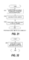
- FIG. 32 is a flowchart of processing executed to create the routing table 2603 according to the fourth embodiment of this invention.
- FIG. 33 is a flowchart of shutdown processing of the virtual machine 602 executed according to the fourth embodiment of this invention.
- control terminal 150 notifies shutting-down of the relevant virtual machine 602 to the I/O channel switch 2501 (3301).
- the switch control unit 2602 specifies a port 2606 used by the relevant virtual machine (i.e., port 2606 allocated to the relevant computer) based on the storage resources control table 621 and the routing table 2603 (3302).
- the switch control unit 2602 executes loop processing for each port specified in Step 3302 (3303 to 3306).
- each port specified in Step 3302 is described as a relevant port 2606.
- Step 3304 the switch control unit 2602 determines whether the relevant port 2606 is used by the other virtual machine 602.
- the hypervisor 103 determines whether the relevant port 2606 has been allocated to the virtual machine 602 other than the relevant virtual machine 602.
- the virtual machine number 1001, the storage port 2901, and the server port 2902 of the storage resources control table 621 are referred to.
- the port (10) 2606 is allocated to the virtual machines (0) 602A and (1) 602B.
- the virtual machine (0) 602A is a relevant virtual machine 602
- the port (10) 2606 is a relevant port 2606, it is determined that the relevant port 2606 has also been allocated to the virtual machine 602 other than the relevant virtual machine 602.
- Step 3304 If it is determined in Step 3304 that the relevant port 2606 has also been allocated to the virtual machine 602 other than the relevant virtual machine 602, the relevant port 2606 is still used by one of the virtual machines 602 even after the relevant virtual machine 602 shuts down. Accordingly, the power of the relevant port 2606 cannot be cut off. In this case, the process proceeds to Step 3306 without cutting off the power of the relevant port 2606.
- Step 3304 if it is determined in Step 3304 that the relevant port 2606 has not been allocated to the virtual machine other than the relevant virtual machine 602, after the relevant virtual machine 602 shuts down, the relevant port 2606 is not used by any one of the virtual machines 602. Thus, the switch control unit 2602 cuts off power of the relevant port 2606 (3305).
- the sever 100 executes the application program which uses the storage system 120.
- a client connected to a network 170 executes an application program which uses a storage system.
- a server system operates as a file server for providing files to the client.
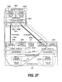
- FIG. 34 is a functional block diagram of a computer system according to the fifth embodiment of this invention.
- the computer system of the fifth embodiment includes clients (0) 3401A and (1) 3401B, file server systems (0) 3403A and (1) 3403B, a storage system 3405, and a control terminal 150.
- a configuration of the computer system is similar to that of the first embodiment except for connection of the clients (0) 3401A and (1) 3401B to the network 170.
- the file server system 3403 corresponds to the server system 100 of the first embodiment. The fifth embodiment will be described below in detail.
- Each of the clients (0) 3401A and (1) 3401B is a computer which includes a CPU (not shown), a memory (not shown), and a LAN adaptor (not shown).
- a memory of each client 3401 stores a program (not shown) for implementing a hypervisor in addition to an application program (not shown).
- virtual clients (0) 3402A and (1) 3402B are generated for the client (0) 3401A
- virtual clients (2) 3402C and (3) 3402D are generated for the client (1) 3401B.
- the file server systems (0) 3403A and (1) 3403B are computers for providing files to the client 3401 via the network 170.
- Hardware configurations of the file server systems (0) 3403A and (1) 3403B are respectively similar to those of the server systems (0) 100A and (1) 100B of the first embodiment, and thus description thereof will be omitted.
- Each file server system 3403 includes a hypervisor 103 for implementing a virtual file server system 3404.
- Virtual file server systems (0) 3404A to (3) 3404D of FIG. 34 respectively correspond to the virtual machines (0) 603A to (3) 603D of FIG. 6B.
- An OS 603 operates in each virtual file server system 3404.
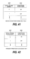
- a server resources control table 653 of the fifth embodiment is different from that of the first embodiment as shown in FIG. 35.
- Virtual file server system shutdown processing executed according to the fifth embodiment is different from the virtual machine shutdown processing executed according to the first embodiment as shown in FIG. 36.
- the virtual file server system 3404 of the fifth embodiment includes a virtual LAN adaptor (not shown).
- a hardware configuration of the storage system 3405 is similar to that of the storage system 120 of the first embodiment, and thus description thereof will be omitted.
- a functional block diagram of the storage system 3405 is also similar to that of the storage system 120 of the first embodiment as shown in FIG. 6C, and thus description thereof will be omitted.
- the storage system 3405 of the fifth embodiment includes four virtual storage systems, i.e., virtual storage systems (0) 3406A to (3) 3406D.
- the virtual file server system (1) 3404B is allocated to the virtual client (1) 3402B, and the virtual storage system (1) 3406B is allocated to the virtual file server system (1) 3404B.
- the virtual file server system (2) 3404C is allocated to the virtual client (2) 3402C, and the virtual storage system (2) 3406C is allocated to the virtual file server system (2) 3404C.
- the virtual file server system (3) 3404D is allocated to the virtual client (3) 3402D, and the virtual storage system (3) 3406D is allocated to the virtual file server system (3) 3404D.
- control terminal 150 is similar to that of the first embodiment, and thus description thereof will be omitted.
- server resources control table 623 included in the virtual machine control program 151 is different from that of the first embodiment.
- FIG. 35 is an explanatory diagram of the server resources control table 623 according to the fifth embodiment of this invention.
- a virtual machine number 701, a CPU utilization rate 702, a memory capacity 703, a virtual I/O adaptor number 704, and an I/O adaptor number 705 in the server resources control table 623 of the fifth embodiment are similar to those of the first embodiment as shown in FIG. 7, and thus description thereof will be omitted. However, an identifier of the virtual file server system 3404 is registered in the virtual machine number 701.
- FIG. 36 is a flowchart of shutdown processing of the virtual file server system 3404 executed according to the fifth embodiment of this invention.
- FIG. 36 The processing of FIG. 36 is executed when power of one of the virtual file server systems 3404 is cut off.
- the virtual file server system 3404 which is to be powered off by the user is described as a relevant virtual file server system 3404.
- the user operates the control terminal 150 to instruct shutting-down to the OS 603 operating in the relevant virtual file server system 3404 (3601).
- the relevant virtual file server system 3404 notifies the shutting-down to the virtual client 3402 which uses the relevant virtual file server system 3403 (3602).
- Steps 3603 to 3609 are respectively similar to Steps 1602 to 1608 of FIG. 16, and thus description thereof will be omitted.
- "Virtual machine 602" in the description of FIG. 16 corresponds to "virtual file server system 3404" of FIG. 36.
- the hypervisor 103 updates the server power control table 651 to reflect the executed cutting of the power (3610).
- the hypervisor 103 reports the cutting of power to the control terminal 150 (3611).
- the control terminal 150 updates the server power control table 624 to reflect the reported cutting of power.
- Steps 3612 to 3617 are respectively similar to Steps 1611 to 1616 of FIG. 16, and thus description thereof will be omitted.
- the storage hypervisor 612 updates the storage power control table 664 to reflect the executed cutting of power (3618).
- FIG. 37 is an explanatory diagram when two virtual machines 602 operate in the computer system of the sixth embodiment.
- control terminal 150 sections unnecessary for explanation (e.g., control terminal 150) are omitted.
- a path from an I/O adaptor (0) 106A through an I/O channel 160A to reach a channel adaptor (0) 129A of a channel board (0) 121A there are two paths, i.e., a path from an I/O adaptor (0) 106A through an I/O channel 160A to reach a channel adaptor (0) 129A of a channel board (0) 121A, and a path from an I/O adaptor (1) 106B through an I/O channel 160B to reach a channel adaptor (2) 129C of a channel board (1) 121B.
- Those two paths are also used for reaching the virtual storage system (1) 613B from the virtual machine (1) 602B.
- the other virtual machine 602 uses the other access path so that concentration of loads is prevented.
- the other of the two virtual machines 602 uses the other access path so that system down can be prevented. Accordingly, high performance and high fault tolerance are realized by giving redundancy to the resources constituting the access path.
- FIG. 38 is an explanatory diagram when one of the virtual machines 602 shuts down in the computer system according to the sixth embodiment of this invention.
- the two access paths are also used by the virtual machine (0) 602A.
- power of physical resources constituting the two access paths is not cut off.
- the two access paths should preferably be maintained. In this case, however, the physical resources constituting the access paths continuously consume power.
- FIG. 39 is an explanatory diagram when redundancy of the resources is released in the computer system according to the sixth embodiment of this invention.
- FIG. 40 is an explanatory diagram of processing executed to cut off power of redundant resources according to the sixth embodiment of this invention.
- control terminal 150 determines whether a virtual resource of a processing target (e.g., virtual machine 602 or virtual storage system 613) has been set to "power saving priority mode" (4001). This determination is made by referring to a table described below with reference to FIGS. 41 and 42.
- a virtual resource of a processing target e.g., virtual machine 602 or virtual storage system 613
- Step 4001 If it is determined in Step 4001 that the virtual resource has not been set to the power saving priority mode, resource redundancy cannot be released. In this case, the process is finished without cutting off power of the resource.
- the control terminal 150 determines whether redundant resources are present (4002).
- the redundant resources mean multiple physical resources allocated to a single virtual resource (e.g., virtual machine 602) such as the physical resources constituting the two access paths shown in FIG. 38.
- Step 4002 If it is determined in Step 4002 that no redundant resource is present, the resource redundancy cannot be released. Thus, the process is finished without cutting off power of the resources.
- Step 4002 if it is determined in Step 4002 that when redundant resources are present, to release allocation of the redundant resources to the virtual resource of a processing target, the control terminal 150 updates a server resources control table 623 shown in FIG. 7 and a storage resources control table 622 shown in FIG. 10 (4003).
- control terminal 150 cuts off power of the redundant resources according to the tables updated in Step 4003 (4004).
- Step 4003 For example, a case of releasing allocation of the access path from the I/O adaptor (1) 106B through the I/O channel 160B to the channel adaptor (2) 129C of the channel board (1) 121B shown in FIGS. 38 and 39 will be described.
- Step 4003 "1" is deleted from an I/O adaptor number 705 corresponding to a value "0" of a virtual machine number 701.
- Step 4002 is deleted from a channel adaptor 1008 corresponding to a value "0" of a virtual storage system number 1002.
- Step 4004 power of the I/O adaptor (1) 106B and the channel adaptor (2) 129C is cut off.
- the process is executed by the control terminal 150. However, similar processing may be executed by a hypervisor 103 or a storage hypervisor 612.
- the server system power saving mode table may be held by the control terminal 150.
- the server system power saving mode table may be held by the hypervisor 103 or the storage hypervisor 612.
- the server system power saving mode table includes at least two columns of a virtual machine number 4101 and a power saving priority mode 4102.
- one of two values "on” and “off' is registered as the power saving priority mode 4102.
- "On” indicates that the virtual machine 602 has been set to the power saving priority mode
- "off” indicates that the virtual machine 602 has not been set to the power saving priority mode.
- the virtual machine (0) 602A has been set to the power saving priority mode.
- FIG. 42 is an explanatory diagram of a storage system power saving mode table according to the sixth embodiment of this invention.
- An identifier of a virtual storage system 613 is registered in the virtual storage system number 4201.
- one of two values "on” and “off” is registered as the power saving priority mode 4202.
- “On” indicates that the virtual storage system 613 has been set to the power saving priority mode
- "off' indicates that the virtual storage system 613 has not been set to the power saving priority mode.
- the virtual storage system (0) 613A has been set to the power saving priority mode.
- FIG. 43 is an explanatory diagram of an input screen used for allocating resources according to the sixth embodiment of this invention.
- FIG. 43 shows an input screen for setting a virtual machine (0) 602A as an example.
- this input screen is displayed by a screen display (not shown).
- three CPU's 101, a disk cache 144 of 2 GB, a 20% internal bandwidth 1006, and three virtual disks 665 are allocated to the virtual machine (0) 602A.
- the virtual machine (0) 602A is set to a power saving priority mode.
- a user of the control terminal 150 can enter an optional value in the input screen of FIG. 43.
- the sixth embodiment has been described by taking the example of giving redundancy to the access path. However, even when other resources are redundant, similar processing to that described above can be applied to the resources.
- a storage hypervisor 612 calculates a capacity necessary for the disk cache 144 (4401). Specifically, the storage hypervisor 612 refers to a storage resources control table 663 as shown in FIG. 10 to sum up values of disk cache capacities 1004 allocated to all virtual storage systems 613.
- the storage hypervisor 612 determines whether power of the disk cache 144 can be cut off (4402). In other words, the storage hypervisor 612 determines whether there is a disk cache 144 which does not hinder running of the virtual storage system 613 even when its power is cut off. Specifically, when the capacity calculated in Step 4401 is smaller than a total capacity of all disk caches 144 disposed in a storage system 120, a capacity difference thereof is not allocated to any virtual storage system 613. Thus, even when power of the disk cache 144 equivalent to the capacity difference is cut off, running of the virtual storage system 613 is not hindered.
- Step 4401 when a capacity calculated in Step 4401 is 10 gigabytes (GB), and a total of capacities of disk caches 144 actually mounted is 16 GB, even when power of the disk cache 144 of 6 GB is cut off, the running of the virtual storage system 613 is not hindered. Accordingly, it is possible to cut off power of a disk cache 144 of maximum 6 GB.
- Step 4402 If it is determined in Step 4402 that power of the disk cache 144 cannot be cut off, the process is finished without cutting off the power of the disk cache 144.
- Step 4402 if it is determined in Step 4402 that the power of the disk cache 144 can be cut off, the storage hypervisor 612 cuts off the power of the disk cache 144 which does not hinder the running of the virtual storage system 613 even when its power is cut off (4403).
- the power of the disk cache 144 may be cut off for each physical memory module. Alternatively, cutting of power may be permitted for each memory bank. Alternatively, cutting of power may be permitted for each memory page.
- power of the memory of 6 GB is cut off as in the case of the aforementioned example, in the case of cutting off power for each memory module of 4 GB, power of only one memory module can be cut off. It is because a cache capacity of 10 GB cannot be ensured when power of two memory modules is cut off.
- the power of the disk cache 144 should preferably be cut off by a unit as small as possible (e.g., each page).
- the power of the disk cache 144 should preferably be cut off. In the above-mentioned case, for example, it is advised to cut off power of the disk caches (0) 144A and (2) 144C.
- the seventh embodiment it is possible to reduce power consumption by cutting off the power of the disk cache 144 which does not hinder the running of the virtual storage system 613 even when its power is cut off.
- the computer system of the first embodiment includes one storage system 120, and two server systems 100 are connected to one storage system 120.
- a computer system of the eighth embodiment includes two storage systems 120, and one server system 100 is connected to each storage system 120. Remote copying is carried out between the two storage systems 120.
- FIG. 45 is a functional block diagram of the computer system according to the eighth embodiment of this invention.
- the server system 100A includes virtual machines (0) 602A and (1) 602B.
- the server system 100B includes virtual machines (2) 602C and (3) 602D.
- Hardware configurations and functional block diagrams of the storage systems 120A and 120B are similar to those of the storage system 120 of the first embodiment, and thus detailed description thereof will be omitted.
- the storage system 120A includes virtual storage systems (0) 613A and (1) 613B.
- the virtual storage system (0) 613A includes virtual disks (0) 665A and (1) 665B.
- the virtual storage system (1) 613B includes virtual disks (16) 665C and (17) 665D.
- the storage system 120B includes a virtual storage system (1') 613C.
- the storage system 120B may include more virtual storage systems 613.
- the virtual storage system (1') 613C includes virtual disks (16') 665E and (17') 665F.
- the virtual storage system (0) 613A is allocated to the virtual machine (0) 602A.
- the virtual machine (0) 602A uses the virtual storage system (0) 613A.
- the virtual storage system (1) 613B is allocated to the virtual machine (1) 602B.
- the virtual storage system (1') 613C is allocated to the virtual machine (2) 602C.
- the storage systems 120A and 120B are installed in places geographically separate from each other.
- the virtual storage systems (1) 613B and (1') 613C are interconnected via a remote network 4501.
- the remote network 4501 is a wide-area communication network to which Internet protocol (IP) is applied.
- IP Internet protocol
- Remote copying is carried out between the virtual storage systems (1) 613B and (1') 613C.
- the remote copying is a technology for copying data stored in the storage system 120 to another storage system to prevent a loss of data caused by a disaster or a system fault. More specifically, a copy of the data stored in the storage system 120 is transmitted to another storage system to be stored in a storage system 120 of a transmission destination.
- the virtual machine (1) 602B requests writing of data in the virtual disk (16) 665C or (17) 665D.
- the virtual storage system (1) 613B writes data in response to the request, and transmits a copy of data written in the virtual disks (16) 655C and (17) 665D to the virtual storage system (1') 613C via the remote network 4501.
- the virtual storage system (1') 613C writes the data written in the virtual disk (16) 665C in a virtual disk (16') 665E, and the data written in the virtual disk (17) 665D in a virtual disk (17') 665F.
- the same data is stored in the virtual disks (16) 665C and (16') 665E, and the same data is stored in the virtual disks (17) 665D and (17') 665F.
- the virtual storage system (1) 613B is a primary virtual storage system 613.
- the virtual storage system (1') 613C is a secondary virtual storage system 613.
- the virtual disks (16) 665C and (17) 665D are primary virtual disks 665.
- the virtual disks (16') 665E and (17') 665F are secondary virtual disks 665.
- the writing may be not be immediately copied to the secondary virtual disk 665.
- data transmission for copying may be executed after the congestion is solved.
- FIG. 46 is an explanatory diagram of a virtual disk control table 622 according to the eighth embodiment of this invention.
- the virtual disk control table 622 holds information for managing allocation of a virtual disk 655 to the virtual machine 602. Additionally, the virtual disk control table 622 of the eighth embodiment holds information for managing a pair of virtual disks 665.
- the virtual machine number 801, the virtual storage number 802, the logical unit number 803, and the virtual disk number 804 are similar to those of the first embodiment, and thus description thereof will be omitted.
- each storage system 120 holds a virtual disk control table 661 including information similar to that of the virtual disk control table 622. Accordingly, in the description below, FIG. 46 is referred to also as an explanatory diagram of the virtual disk control table 661. However, the virtual disk control table 661 may include only information regarding a storage system 120 which holds the virtual disk control table 661.
- the virtual machine (1) 602B shuts down (4701).
- the virtual storage system (1) 613B determines whether the virtual storage system (1) 613B includes a virtual disk 665 belonging to a pair by referring to the virtual disk control table 661 (4704). Specifically, when at least one of values of the pair state 4601 corresponding to a value "1" of the virtual storage number 802 is "1" or "2", it is determined that the virtual storage system (1) 613B includes the virtual disk 665 belonging to the pair.
- Step 4704 If it is determined in Step 4704 that the virtual storage system (1) 613B does not include the virtual disk 665 belonging to the pair, the virtual storage system (1) 613B shuts down (4705) and the process is finished. In this case, Steps 1612 to 1618 of FIG. 16 are executed in Step 4705.
- Step 4704 if it is determined in Step 4704 that the virtual storage system (1) 613B includes the virtual disk 665 belonging to the pair, the virtual storage system (1) 613B determines whether the virtual disk 665 belonging to the pair is a primary virtual disk 665 (4706).
- Step 4706 If it is determined in Step 4706 that the virtual disk 665 belonging to the pair is not a primary virtual disk 665, the virtual storage system (1) 613B includes a secondary virtual disk 665. In this case, as the virtual storage system (1) 613B cannot be shut down, the process is finished without executing shutting-down. The reason is as follows.
- the virtual storage system 613 including the secondary virtual disk 665 shuts down before a copy of data written in the primary virtual disk 665 is transmitted to the secondary virtual disk 665, inconsistency of data occurs between the primary virtual disk 665 and the secondary virtual disk 665. Use of the inconsistent data may be inhibited.
- the secondary virtual storage system 613 cannot know whether there still remains data not copied in the secondary virtual disk 665 until it obtains information from the primary virtual storage system 613. Accordingly, the secondary virtual storage system 613 cannot be shut down according to a shutting-down instruction from the control terminal 150.
- the secondary virtual storage system 613 can be shut down upon reception of a shutting-down instruction from the primary virtual storage system 613.
- Step 4706 if it is determined in Step 4706 that the virtual disk 665 belonging to the pair is a primary virtual disk 665, the virtual storage system (1) 613B determines whether there still remains data not transmitted to the secondary virtual storage system 613 (4707).
- the data not having been transmitted is a copy of data written in the primary virtual disk 665, and not transmitted to the secondary virtual storage system 613 yet.
- Step 4707 If it is determined in Step 4707 that there still remains data not having been transmitted, the virtual storage system (1) 613B transmits the untransmitted data (4708).
- the secondary virtual storage system 613 that has received the data writes the received data in the secondary virtual disk 665.
- the virtual storage system (1) 613B transmits a shutting-down instruction to the secondary virtual storage system (in the example of FIG. 45, the virtual storage system (1') 613C) (4709).
- Step 4707 determines that there does not remain data not having been transmitted. If it is determined in Step 4707 that there does not remain data not having been transmitted, the virtual storage system (1) 613B executes Step 4709 without executing Step 4708.
- the virtual storage system (1) 613B determines whether the virtual storage system (1) 613B is allocated to the other virtual machine 602 (4710).
- the other virtual machine 602 means a virtual machine 602 other than the virtual machine (1) 602A shut down in Step 4701.
- the determination of Step 4701 is executed by referring to the virtual machine number 801 and the virtual storage number 802 of the virtual disk control table 622 shown in FIG. 46.
- Step 4710 If it is determined in Step 4710 that the virtual storage system (1) 613B has been allocated to the other virtual machine 602, even after the virtual machine (1) 602A shuts down, the virtual storage system (1) 613B is used by the other virtual machine 602. Accordingly, the process is finished without shutting down the virtual storage system (1) 613B.
- Step 4710 if it is determined in Step 4710 that the virtual storage system (1) 613B has not been allocated to any other virtual machines 602, after the virtual machine (1) 602A shuts down, the virtual storage system (1) 613B is not used by any virtual machines 602. In this case, shutting-down of the virtual storage system (1) 613B is executed (4711) and the process is finished. In this case, in Step 4711, Steps 1612 to 1618 of FIG. 16 are executed.
- FIG. 48 is a flowchart showing processing executed by the secondary virtual storage system 613 which has received a shutting-down instruction from the primary virtual storage system 613 according to the eighth embodiment of this invention.
- the processing of FIG. 48 is executed by the secondary virtual storage system 613 which has received the instruction transmitted in Step 4709 of FIG. 47.
- a case where the secondary virtual storage system 613 is a virtual storage system (1') 613C as in the case of FIG. 45 will be described below.
- the virtual storage system (1') 613C receives a shutting-down instruction from the primary virtual storage system (1) 613B (4801). This instruction is transmitted in Step 4709 of FIG. 47.
- the virtual storage system (1') 613C determines whether the virtual storage system (1') 613C is allocated to the other virtual machine 602 (4802).
- the other virtual machine 602 means a virtual machine 602 to which the virtual disk 665 other than the virtual disk 665 belonging to the same pair of the virtual disk 665 allocated to the virtual machine 602 shut down in Step 4701 has been allocated among the virtual machines 602 to which the virtual storage system (1') 613C has been allocated.
- Step 4701 the virtual storage system (1) 613B shuts down.
- Virtual disks (16) 665C and (7) 665D have been allocated to the virtual storage system (1) 613B.
- the virtual disks (16') 665E and (17') 665F belong to the same pairs of the virtual disks (16) 665C and (17) 665D. Accordingly, a virtual machine 602 to which a virtual disk 665 other than the virtual disks (16') 665E and (17') 665F has been allocated is the other virtual machine 602 in Step 4802.
- Step 4802 it is determined that the virtual storage system (1') 613C has not been allocated to the other virtual machine 602.
- Step 4802 If it is determined in Step 4802 that the virtual storage system (1') 613C has been allocated to the other virtual machine 602, the processing is finished without shutting down the virtual storage system (1') 613C.
- Step 4803 the control terminal 150 may transmit a shutting-down instruction to the virtual machine (2) 602C to which the virtual storage system (1') 613C to be shut down has been allocated.
- the secondary virtual storage system 613 belonging to the same pair of the primary virtual storage system 613 i.e., secondary virtual storage system 613 including the secondary virtual disk 665 of the copying destination of the data written in the virtual disk 665 of the primary virtual storage system 613 is shut down.
- the secondary virtual storage system 613 belonging to the same pair of the primary virtual storage system 613 (i.e., secondary virtual storage system 613 including the secondary virtual disk 665 of the copying destination of the data written in the virtual disk 665 of the primary virtual storage system 613) is shut down.
- the computer system of the first embodiment includes one storage system 120, and the two server systems 100 are connected to one storage system 120.
- a computer system of the ninth embodiment includes two storage systems 120.
- One storage system 120 is externally connected to the other storage system 120.
- FIG. 49 is a functional block diagram of the computer system according to the ninth embodiment of this invention.
- the server system (0) 100A includes virtual machines (0) 602A and (1) 602B.
- Hardware configurations and functional block diagrams of the storage systems (0) 120A and (1) 120B are similar to those of the storage system 120 of the first embodiment, and thus detailed description thereof will be omitted.
- the storage system (0) 120A includes a virtual storage system ( n ) 613E.
- the virtual storage system ( n ) 613E includes virtual disks (121) 665G, (122) 665H, (300) 665J, and (301) 665K.
- the storage system (1) 120B includes a virtual storage system ( n + 1) 613F.
- the virtual storage system ( n + 1) 613F includes virtual disks (500) 665L and (501) 665M.
- the virtual storage system ( n ) 613E is externally connected to the virtual storage system ( n + 1) 613F.
- the virtual disk (500) 665L is externally connected to the virtual disk (300) 665J
- the virtual disk (501) 665M is externally connected to the virtual disk (301) 665K.
- no physical disk drive 148 in the storage system (0) 120A is allocated to the virtual disks (300) 665J or (301) 665K.
- FIG. 50 is an explanatory diagram of a disk address translation table 662 according to the ninth embodiment of this invention.
- the disk address translation table 662 holds information for managing a correlation between the virtual disk 665 in the virtual storage system 613 and the physical disk drive 148 allocated to the virtual disk 665. Additionally, the disk address translation table 662 holds information for managing a correlation between the virtual disk 665 in the virtual storage system 613 and a virtual disk 665 in another storage system 613 externally connected to the virtual disk 665.
- the disk address translation table 662 of the ninth embodiment includes six columns of a virtual storage system number 5001, a virtual disk number 901, a virtual block address 902, a physical disk number 903, a physical block address 904, and an external disk flag 5002.
- An identifier of the physical disk drive 148 allocated to the virtual disk 665 is registered in the physical disk number 903. However, when a virtual disk 665 in another virtual storage system 613 is externally connected to the virtual disk 665, an identifier of the externally connected virtual disk 665 is registered in the physical disk number 903.
- a physical block address for uniquely identifying a logical block of the physical disk drive 148 allocated to the virtual disk 665 in each physical disk drive is registered in the physical block address 904.
- a virtual block address of the externally connected virtual disk 665 is registered in the physical block address 904.
- Information indicating external connection of another virtual disk 665 to the virtual disk 665 indicated by the virtual disk 901 is registered in the external disk flag 5002.
- the virtual disk 665 is externally connected
- "1" is registered in the external disk flag 5002.
- an identifier of the externally connected virtual disk 655 and a virtual block address in the externally connected virtual disk 655 are registered in the physical disk number 903 and the physical block address 904, respectively.
- the virtual storage system ( n ) 613E upon reception of an access request targeting the address "0x00000000" of the virtual disk (300) 665J, the virtual storage system ( n ) 613E transmits an access request obtained by converting the target of the received access request into an address "0x00000000" of the virtual disk (500) 665L to the virtual storage system ( n + 1) 613F.
- FIG. 51 is an explanatory diagram of a storage resources control table 621 according to the ninth embodiment of this invention.
- FIG. 52 is a flowchart of shutdown processing of the virtual machine 602 executed according to the ninth embodiment of this invention.
- the processing of FIG. 52 is executed when the user cuts off power of one of the virtual machines 602.
- the shutdown processing shown in FIG. 52 of the virtual machine 602 of the ninth embodiment is similar to that of the first embodiment shown in FIG. 16 except for differences below. Differences of the shutdown processing of the virtual machine 602 of the ninth embodiment from that of the first embodiment will be described below. Meanings of "relevant resource”, “ relevant virtual storage system 613" and the like are as described above referring to FIG. 16.
- shutting-down of the virtual machine is executed (5201). This processing corresponds to Steps 1601 to 1610 of FIG. 16, and thus description thereof will be omitted.
- Steps 5202 to 5205 are respectively similar to Steps 1611 to 1614 of FIG. 16, and thus description thereof will be omitted.
- Step 5206 If it is determined in Step 5206 that the relevant resource is an external disk, the relevant resource is included in a storage system 120 different from that including the relevant virtual storage system 613. Accordingly, the storage hypervisor 612 of the storage system 120 including the relevant storage system 613 cannot directly control power of the relevant resource. In this case, the storage hypervisor 612 determines whether the relevant resource is managed by one of the virtual storage systems 613 (5207).
- Step 5207 If it is determined in Step 5207 that the relevant resource is managed by one of the virtual storage systems 613, the storage hypervisor 612 transmits an instruction to power off the relevant resource to the virtual storage system 613 which manages the relevant resource (5208).
- Step 5207 if it is determined in Step 5207 that the relevant resource is not managed by any virtual storage system 613, the process proceeds to Step 5210 without cutting off the power of the relevant resource.
- Step 5206 If it is determined in Step 5206 that the relevant resource is not an external disk, the relevant resource is included in the storage system 120 which includes the relevant virtual storage system 613. In this case, the process proceeds to Step 5209. Steps 5209 to 5212 are respectively similar to Steps 1615 to 1618 of FIG. 16, and thus description thereof will be omitted.
- Step 5201 the shutting-down of the virtual machine (0) 602A is finished.
- Virtual disks (121) 665G, (122) 665H, (300) 665J, and (301) 665K have been allocated to the virtual machine (0) 602A as shown in FIG. 51.
- Physical disk drives (8) 148 and (9) 148 have been allocated to the virtual disk (121) 665G as shown in FIG. 50.
- a physical disk drive (10) 148 has been allocated to the virtual disk (122) 665H.
- An externally connected virtual disk (500) 665L has been allocated to the virtual disk (300) 665J.
- An externally connected virtual disk (501) 665M has been allocated to the virtual disk (301) 665K.
- Step 5206 it is determined that the relevant resource is not an external disk.
- the virtual disks (500) 665L and (501) 665M in Step 5206, it is determined that the relevant resource is an external disk.
- the externally connected virtual storage system 613 is allocated to the virtual machine 602.
- the virtual machine 602 shuts down
- power of physical resources allocated to the externally connected virtual storage system 613 is shut down.
- the virtual storage system 613 when the virtual storage system 613 shuts down, it is determined whether the physical resources allocated to the device have been allocated to the other device. Then, the power of the physical resources not allocated to the other device is cut off as shown in FIG. 16 or the like. On the other hand, when even a resource allocated to the shut-down virtual storage system 613 has been allocated to the other virtual storage system 613, power of the resource cannot be cut off.
- a load imposed on the resource allocated to the virtual storage system 613 is to be reduced as a result of shutting down the virtual storage system 613.
- it is possible to cut off power of resources unnecessary for the virtual storage system 613 can be cut off according to the reduced load. In other words, only resources necessary for covering loads imposed by the running virtual storage system are left, and power of the other resources is cut off. Accordingly, it is possible to reduce power consumption without lowering performance of the virtual storage system.
- the tenth embodiment it is determined whether power of physical resources is powered based on a utilization rate of the physical resources. Referring to FIGS. 53 and 54, the tenth embodiment will be described below in detail.
- FIG. 53 is a functional block diagram of a computer system according to the tenth embodiment.
- the computer system of the tenth embodiment includes a server system (0) 100A, a storage system (0) 120, and a control terminal 150.
- a hardware configuration and a functional block diagram of the server system (0) 120 are similar to those of the storage system 120 of the first embodiment, and thus detailed description thereof will be omitted.
- the storage system (0) 120 includes virtual storage systems (n) 613E and ( n + 1) 613F.
- CPU's (4) 122A, (6) 122C, (8) 133A, and (10) 133C have been allocated to the virtual storage system ( n ) 613E.
- CPU's (4) 122A, (6) 122C, (8) 133A, and (10) 133C have been allocated to the virtual storage system ( n + 1) 613F.
- each CPU 122 or the like has been allocated to two virtual storage systems 613.
- the virtual storage system ( n ) 613E allocated to the virtual machine (0) 602A also shuts down.
- the CPU's (4) 122A, (6) 122C, (8) 133A, and (10) 133C have all been allocated to the virtual storage system ( n + 1) 613F. Accordingly, power of these CPU's cannot be cut off.
- an average utilization rate of the four CPU's 122 or the like is 100% as a result of imposing the same amount of loads on the storage system 120 by the virtual machines (0) 602A and (1) 602B.
- the average utilization rate of the four CPU's 122 or the like is reduced to 50%.
- an average utilization rate of the remaining two CPU's 122 or the like is expected to be 100%.
- the virtual machine (1) 602B needs only two CPU's 122.
- the load imposed on the CPU 122 or the like can be covered by the remaining two CPU's 122 or the like. Accordingly, by cutting off power of the two CPU's 122 or the like, it is possible to reduce power consumption without lowering performance of the virtual storage system ( n + 1) 613F. Referring to FIG. 54, processing thus executed will be described.
- FIG. 54 is a flowchart of processing to power off physical resources based on a utilization rate executed according to the tenth embodiment of this invention.
- FIG. 54 a case where the virtual storage system ( n ) 613E shuts down in FIG. 53 will be described as an example.
- shutting-down of the virtual storage system ( n ) 613E is completed (5401).
- the completion of this shutting-down is equivalent to an end of Step 1618 of FIG. 16.
- the storage hypervisor 612 specifies a resource allocated to the shut-down virtual storage system ( n ) 613E (5402). This specification is executed as in the case of Step 1612 of FIG. 16.
- the storage hypervisor 612 determines whether there are a plurality of resources similar in kind to the relevant resource and capable of individual controlling of power (5404). In other words, it is determined whether the relevant resource includes a plurality of devices whose power can be individually controlled.
- a CPU group constituted of four CPU's 122 or the like includes a plurality of devices (i.e., CPU 122 or the like) whose power can individually be controlled.
- Step 5404 it is determined that a plurality of resources similar in kind to the relevant resource are present.
- Step 5403 If it is determined in Step 5403 that a plurality of resources similar in kind to the relevant resource are not present, the power of the relevant resource cannot be cut off. In this case, the process is finished without executing cutting off of the power in Step 5406 described below.
- the storage hypervisor 612 determines whether an average utilization rate u of the plurality of resources is equal to or less than 1 - 1/ x (5405).
- x is a total value of the number of the relevant resource detected in Step 5404 and the resources similar in kind to the relevant resource.
- Step 5405 If it is determined in Step 5405 that the average utilization rate u is larger than 1 - 1/ x , when the power of the relevant resource (or one of the resources of the similar kind) is cut off, the remaining resources cannot cover loads imposed thereon. Thus, the processing is finished without executing cutting-off of the power in Step 5406 described below.
- Step 5405 if it is determined in Step 5405 that the average utilization rate u is equal to or less than 1 - 1/ x , even when power of at least one resource is cut off, the remaining resources can cover loads imposed thereon.
- the storage hypervisor 612 cuts off power of x (1 - u ) resources among the relevant resource and the resources of the similar kind (5406).
- x (1 - u ) is not an integer, values after the decimal point are discarded.
- An integer part of x (1 - u ) indicates the number of resources unnecessary for the virtual storage system 613.
- Step 5405 when the average utilization rate of the four CPU's 122 or the like is 60%, u is "0.6" and x is "4". In this case, 1 - 1/ x is 0.75, "yes” is determined in Step 5405. Because x (1 - u ) is 1.6, power of one CPU 122 or the like is cut off in Step 5406.
- the processing of FIG. 54 is executed after the processing of FIG. 16 is finished.
- FIG. 55 is a functional block diagram of a computer system according to the eleventh embodiment of this invention.
- the hypervisor 103 implements the plurality of virtual machines 602 in one computer by setting the logical partitions in each server system 100.
- the storage hypervisor 612 implements the plurality of virtual storage systems 613 in one storage system 120.
- these hypervisors can allocate physical resources of a plurality of devices to one virtual device (i.e., virtual machine 602 or virtual storage system 613) by setting logical partitions over the plurality of devices.
- the computer system of the eleventh embodiment shown in FIG. 55 includes n server systems 100 constituted of server systems (0) 100A to ( n - 1) 100C, and m storage systems 120 constituted of storage systems (0) 120A to ( m - 1) 120C.
- the server system 100 and the storage system 120 are connected to each other via a storage area network (SAN) 5501. Additionally, the server system 100 and the storage system 120 are connected to a control terminal 150 via a network 170.
- SAN storage area network
- a hypervisor 103 that manages all the server systems 100 realizes a plurality of virtual machines 602. Specifically, virtual machines (0) 602A, (1) 602B, and (2) 602C are set over the server systems (0) 100A and (1) 100B. Physical resources of the server systems (0) 100A and (1) 100B are allocated to these virtual machines 602. Additionally, a virtual machine (3) 602D to which physical resources of the server system ( n - 1) 100C alone are allocated is set.
- a storage hypervisor 612 that manages all the storage systems 120 realizes a plurality of virtual storage systems 613. Specifically, virtual storage systems (0) 613A, (1) 613B, and (2) 613C are set over the storage systems (0) 120A and (1) 120B. Physical resources of the storage systems (0) 120A and (1) 120B are allocated to these virtual storage systems 613. Additionally, a virtual storage system (3) 613D to which physical resources of the storage system ( m - 1) 120C alone is set.
- the first to tenth embodiments can be applied to the computer system where the physical resources of the plurality of devices are allocated to the virtual machine 602 and the virtual storage system 612. In this case, processing similar to the aforementioned processing is executed.
Landscapes
- Engineering & Computer Science (AREA)
- Theoretical Computer Science (AREA)
- Physics & Mathematics (AREA)
- General Engineering & Computer Science (AREA)
- General Physics & Mathematics (AREA)
- Software Systems (AREA)
- Human Computer Interaction (AREA)
- Computer Networks & Wireless Communication (AREA)
- Signal Processing (AREA)
- Power Sources (AREA)
Applications Claiming Priority (1)
| Application Number | Priority Date | Filing Date | Title |
|---|---|---|---|
| JP2006283571A JP4847272B2 (ja) | 2006-10-18 | 2006-10-18 | 論理区画ごとに電源を管理する計算機システム、ストレージ装置及びそれらの制御方法 |
Publications (2)
| Publication Number | Publication Date |
|---|---|
| EP1914620A2 true EP1914620A2 (fr) | 2008-04-23 |
| EP1914620A3 EP1914620A3 (fr) | 2011-10-26 |
Family
ID=38925588
Family Applications (1)
| Application Number | Title | Priority Date | Filing Date |
|---|---|---|---|
| EP20070252262 Withdrawn EP1914620A3 (fr) | 2006-10-18 | 2007-06-05 | Système informatique, système de stockage pour le contrôle de l'alimentation électrique basé sur une partition logique |
Country Status (3)
| Country | Link |
|---|---|
| US (1) | US8458432B2 (fr) |
| EP (1) | EP1914620A3 (fr) |
| JP (1) | JP4847272B2 (fr) |
Cited By (2)
| Publication number | Priority date | Publication date | Assignee | Title |
|---|---|---|---|---|
| EP2458501A1 (fr) * | 2010-11-30 | 2012-05-30 | France Telecom | Procédé de fonctionnement d'un dispositif de communication et dispositif de communication apparenté |
| CN102972010A (zh) * | 2012-08-17 | 2013-03-13 | 华为技术有限公司 | 一种云环境下虚拟应用双机的切换方法、装置及系统 |
Families Citing this family (69)
| Publication number | Priority date | Publication date | Assignee | Title |
|---|---|---|---|---|
| US7774650B2 (en) * | 2007-01-23 | 2010-08-10 | International Business Machines Corporation | Power failure warning in logically partitioned enclosures |
| US20080229050A1 (en) * | 2007-03-13 | 2008-09-18 | Sony Ericsson Mobile Communications Ab | Dynamic page on demand buffer size for power savings |
| JP4964671B2 (ja) * | 2007-05-21 | 2012-07-04 | 株式会社日立製作所 | 計算機システムの電力制御方法、プログラム、及び計算機システム |
| US8689224B2 (en) * | 2007-09-26 | 2014-04-01 | The Boeing Company | Methods and systems for preserving certified software through virtualization |
| US8522237B2 (en) * | 2008-04-09 | 2013-08-27 | The Boeing Company | Virtualizing embedded systems |
| JP4838832B2 (ja) * | 2008-08-29 | 2011-12-14 | 富士通株式会社 | ストレージシステムの制御方法、ストレージシステム、及びストレージ装置 |
| JP5026375B2 (ja) | 2008-09-09 | 2012-09-12 | 株式会社日立製作所 | ストレージ装置及びストレージ装置の制御方法 |
| US8504857B1 (en) * | 2008-09-30 | 2013-08-06 | Emc Corporation | Programmable availability for a high availability system |
| JP2010097533A (ja) | 2008-10-20 | 2010-04-30 | Hitachi Ltd | パーティションで区切られた計算機システムにおけるアプリケーション移動及び消費電力の最適化 |
| US8041987B2 (en) * | 2008-11-10 | 2011-10-18 | International Business Machines Corporation | Dynamic physical and virtual multipath I/O |
| JP5024561B2 (ja) * | 2008-12-18 | 2012-09-12 | 日本電気株式会社 | 情報処理装置及び入出力パスの切替方法 |
| JP4893731B2 (ja) * | 2008-12-25 | 2012-03-07 | 富士通株式会社 | 通信制御装置 |
| JP2010152643A (ja) * | 2008-12-25 | 2010-07-08 | Fujitsu Ltd | データ転送装置、データ記憶装置及び方法 |
| US8230245B2 (en) * | 2009-01-23 | 2012-07-24 | Dell Products, L.P. | Method and system for operating-system-independent power management using performance verifications |
| JP5626839B2 (ja) | 2010-03-19 | 2014-11-19 | 富士通株式会社 | 仮想計算機システム、仮想計算機制御装置および仮想計算機システムの実行方法 |
| JP2012018515A (ja) * | 2010-07-07 | 2012-01-26 | Fujitsu Ltd | 情報処理装置,制御方法,制御プログラム |
| US9411517B2 (en) | 2010-08-30 | 2016-08-09 | Vmware, Inc. | System software interfaces for space-optimized block devices |
| US9285993B2 (en) | 2010-08-30 | 2016-03-15 | Vmware, Inc. | Error handling methods for virtualized computer systems employing space-optimized block devices |
| JP5691390B2 (ja) * | 2010-10-25 | 2015-04-01 | サンケン電気株式会社 | 電源装置およびプログラム |
| US9384052B2 (en) * | 2010-12-20 | 2016-07-05 | Microsoft Technology Licensing, Llc | Resilient message passing in applications executing separate threads in a plurality of virtual compute nodes |
| US9201677B2 (en) * | 2011-05-23 | 2015-12-01 | Intelligent Intellectual Property Holdings 2 Llc | Managing data input/output operations |
| US8966478B2 (en) | 2011-06-28 | 2015-02-24 | The Boeing Company | Methods and systems for executing software applications using hardware abstraction |
| US9594770B1 (en) * | 2011-06-28 | 2017-03-14 | EMC IP Holding Company LLC | Score-based selection of storage device for virtual disk with specification of quality of service |
| JP5263347B2 (ja) * | 2011-07-19 | 2013-08-14 | 富士通株式会社 | ストレージシステムの制御方法、ストレージシステム、及びストレージ装置 |
| JP5884365B2 (ja) * | 2011-09-27 | 2016-03-15 | サンケン電気株式会社 | 電源装置およびプログラム |
| US9129124B2 (en) * | 2012-04-12 | 2015-09-08 | Hewlett-Packard Development Company, L.P. | Dynamic provisioning of virtual systems |
| US9336035B2 (en) * | 2012-10-23 | 2016-05-10 | Vmware, Inc. | Method and system for VM-granular I/O caching |
| US8996778B2 (en) * | 2012-12-13 | 2015-03-31 | Lenovo Enterprise Solutions (Singapore) Pte. Ltd. | Cable adapter correlation in a cluster |
| US9055119B2 (en) | 2013-03-26 | 2015-06-09 | Vmware, Inc. | Method and system for VM-granular SSD/FLASH cache live migration |
| US9304700B2 (en) * | 2013-04-18 | 2016-04-05 | Netapp, Inc. | Method and system for remotely controlling a storage shelf of a storage system |
| KR20150000074A (ko) * | 2013-06-21 | 2015-01-02 | 한국전자통신연구원 | 가상 머신 고장 디스크 복구 방법 및 장치 |
| JP6200707B2 (ja) * | 2013-06-28 | 2017-09-20 | 富士通株式会社 | スイッチおよび制御方法 |
| US9870568B2 (en) * | 2013-11-19 | 2018-01-16 | Xerox Corporation | Methods and systems to price customized virtual machines |
| JP2015212888A (ja) * | 2014-05-02 | 2015-11-26 | 富士通株式会社 | 電源制御装置、電源制御プログラム、及び電源制御システム |
| EP3140734B1 (fr) | 2014-05-09 | 2020-04-08 | Nutanix, Inc. | Mécanisme pour fournir un accès externe à un environnement de virtualisation en réseau sécurisé |
| US10664182B2 (en) * | 2015-01-29 | 2020-05-26 | Hitachi, Ltd. | Storage system |
| WO2017051453A1 (fr) * | 2015-09-24 | 2017-03-30 | 株式会社日立製作所 | Système de stockage et procédé de gestion de système de stockage |
| US10095506B2 (en) | 2016-02-12 | 2018-10-09 | Nutanix, Inc. | Virtualized file server data sharing |
| US11218418B2 (en) | 2016-05-20 | 2022-01-04 | Nutanix, Inc. | Scalable leadership election in a multi-processing computing environment |
| US11562034B2 (en) | 2016-12-02 | 2023-01-24 | Nutanix, Inc. | Transparent referrals for distributed file servers |
| US11568073B2 (en) | 2016-12-02 | 2023-01-31 | Nutanix, Inc. | Handling permissions for virtualized file servers |
| US10728090B2 (en) | 2016-12-02 | 2020-07-28 | Nutanix, Inc. | Configuring network segmentation for a virtualization environment |
| US10824455B2 (en) * | 2016-12-02 | 2020-11-03 | Nutanix, Inc. | Virtualized server systems and methods including load balancing for virtualized file servers |
| US11294777B2 (en) | 2016-12-05 | 2022-04-05 | Nutanix, Inc. | Disaster recovery for distributed file servers, including metadata fixers |
| US11281484B2 (en) * | 2016-12-06 | 2022-03-22 | Nutanix, Inc. | Virtualized server systems and methods including scaling of file system virtual machines |
| US11288239B2 (en) | 2016-12-06 | 2022-03-29 | Nutanix, Inc. | Cloning virtualized file servers |
| US11086826B2 (en) | 2018-04-30 | 2021-08-10 | Nutanix, Inc. | Virtualized server systems and methods including domain joining techniques |
| US11194680B2 (en) | 2018-07-20 | 2021-12-07 | Nutanix, Inc. | Two node clusters recovery on a failure |
| US11770447B2 (en) | 2018-10-31 | 2023-09-26 | Nutanix, Inc. | Managing high-availability file servers |
| US11683156B2 (en) * | 2019-07-09 | 2023-06-20 | International Business Machines Corporation | Securely retrieving encryption keys for a storage system |
| US12541431B2 (en) | 2019-12-31 | 2026-02-03 | Nutanix, Inc. | Parallel change file tracking in a distributed file server virtual machine (FSVM) architecture |
| US11768809B2 (en) | 2020-05-08 | 2023-09-26 | Nutanix, Inc. | Managing incremental snapshots for fast leader node bring-up |
| US12248435B2 (en) | 2021-03-31 | 2025-03-11 | Nutanix, Inc. | File analytics systems and methods |
| US12131192B2 (en) | 2021-03-18 | 2024-10-29 | Nutanix, Inc. | Scope-based distributed lock infrastructure for virtualized file server |
| US12197398B2 (en) | 2021-03-31 | 2025-01-14 | Nutanix, Inc. | Virtualized file servers and methods to persistently store file system event data |
| US12367108B2 (en) | 2021-03-31 | 2025-07-22 | Nutanix, Inc. | File analytics systems and methods including retrieving metadata from file system snapshots |
| US12242455B2 (en) | 2021-03-31 | 2025-03-04 | Nutanix, Inc. | File analytics systems and methods including receiving and processing file system event data in order |
| US12248434B2 (en) | 2021-03-31 | 2025-03-11 | Nutanix, Inc. | File analytics systems including examples providing metrics adjusted for application operation |
| US12164383B2 (en) | 2021-08-19 | 2024-12-10 | Nutanix, Inc. | Failover and failback of distributed file servers |
| US12117972B2 (en) | 2021-08-19 | 2024-10-15 | Nutanix, Inc. | File server managers and systems for managing virtualized file servers |
| JP7661936B2 (ja) * | 2022-01-20 | 2025-04-15 | オムロン株式会社 | 情報処理装置、管理プログラム、管理方法、および、情報処理システム |
| US12153690B2 (en) | 2022-01-24 | 2024-11-26 | Nutanix, Inc. | Consistent access control lists across file servers for local users in a distributed file server environment |
| US12182264B2 (en) | 2022-03-11 | 2024-12-31 | Nutanix, Inc. | Malicious activity detection, validation, and remediation in virtualized file servers |
| US12189499B2 (en) | 2022-07-29 | 2025-01-07 | Nutanix, Inc. | Self-service restore (SSR) snapshot replication with share-level file system disaster recovery on virtualized file servers |
| US12572503B2 (en) | 2022-08-26 | 2026-03-10 | Nutanix, Inc. | Application level to share level replication policy transition for file server disaster recovery systems |
| US12517874B2 (en) | 2022-09-30 | 2026-01-06 | Nutanix, Inc. | Data analytics systems for file systems including tiering |
| US12627681B2 (en) | 2023-06-26 | 2026-05-12 | Nutanix, Inc. | Ransomware detection and/or remediation as a service in file server systems |
| US12461832B2 (en) | 2023-09-27 | 2025-11-04 | Nutanix, Inc. | Durable handle management for failover in distributed file servers |
| US12619754B2 (en) | 2023-09-27 | 2026-05-05 | Nutanix, Inc. | Systems and methods for generating consistent global identifiers within a distributed file server environment including examples of global identifiers across domains |
Citations (2)
| Publication number | Priority date | Publication date | Assignee | Title |
|---|---|---|---|---|
| US20040111596A1 (en) | 2002-12-09 | 2004-06-10 | International Business Machines Corporation | Power conservation in partitioned data processing systems |
| GB2419703A (en) | 2004-10-29 | 2006-05-03 | Hewlett Packard Development Co | Isolated virtual overlay infrastructures each having an interface to control interaction with others |
Family Cites Families (18)
| Publication number | Priority date | Publication date | Assignee | Title |
|---|---|---|---|---|
| JPH04308940A (ja) * | 1991-04-05 | 1992-10-30 | Hitachi Ltd | 仮想計算機システムにおける資源の自動割当て管理方式 |
| JPH06250858A (ja) * | 1993-02-24 | 1994-09-09 | Hitachi Ltd | 仮想計算機システム |
| JPH09282057A (ja) * | 1996-04-18 | 1997-10-31 | Nippon Denki Joho Service Kk | システム電源制御装置 |
| JPH11202988A (ja) * | 1998-01-13 | 1999-07-30 | Hitachi Ltd | システム消費電力制御方法 |
| JP2001043098A (ja) * | 1999-07-29 | 2001-02-16 | Matsushita Electric Ind Co Ltd | オペレーティングシステムおよび仮想計算機システム |
| US7870241B2 (en) * | 2002-11-27 | 2011-01-11 | International Business Machines Corporation | Automated power control policies based on application-specific redundancy characteristics |
| US7477655B2 (en) * | 2003-07-21 | 2009-01-13 | Qlogic, Corporation | Method and system for power control of fibre channel switches |
| US20050060590A1 (en) * | 2003-09-16 | 2005-03-17 | International Business Machines Corporation | Power-aware workload balancing usig virtual machines |
| JP4257783B2 (ja) * | 2003-10-23 | 2009-04-22 | 株式会社日立製作所 | 論理分割可能な記憶装置及び記憶装置システム |
| JP2005190036A (ja) * | 2003-12-25 | 2005-07-14 | Hitachi Ltd | 記憶制御装置及び記憶制御装置の制御方法 |
| JP4518541B2 (ja) * | 2004-01-16 | 2010-08-04 | 株式会社日立製作所 | ディスクアレイ装置及びディスクアレイ装置の制御方法 |
| JP4227035B2 (ja) * | 2004-02-03 | 2009-02-18 | 株式会社日立製作所 | 計算機システム、管理装置、ストレージ装置及びコンピュータ装置 |
| JP3834323B2 (ja) * | 2004-04-30 | 2006-10-18 | 日本電気株式会社 | キャッシュメモリおよびキャッシュ制御方法 |
| US7401240B2 (en) * | 2004-06-03 | 2008-07-15 | International Business Machines Corporation | Method for dynamically managing power in microprocessor chips according to present processing demands |
| JP2006085503A (ja) * | 2004-09-16 | 2006-03-30 | Nec Corp | 電源供給制御装置および電源供給制御方法 |
| JP4349274B2 (ja) * | 2004-12-20 | 2009-10-21 | 日本電気株式会社 | 磁気ディスク装置および制御方法 |
| JP4733399B2 (ja) * | 2005-01-28 | 2011-07-27 | 株式会社日立製作所 | 計算機システム、計算機、ストレージ装置及び管理端末 |
| JP5036158B2 (ja) * | 2005-10-05 | 2012-09-26 | 株式会社日立製作所 | 情報処理システム及び情報処理システムの制御方法 |
-
2006
- 2006-10-18 JP JP2006283571A patent/JP4847272B2/ja not_active Expired - Fee Related
-
2007
- 2007-01-11 US US11/622,271 patent/US8458432B2/en not_active Expired - Fee Related
- 2007-06-05 EP EP20070252262 patent/EP1914620A3/fr not_active Withdrawn
Patent Citations (2)
| Publication number | Priority date | Publication date | Assignee | Title |
|---|---|---|---|---|
| US20040111596A1 (en) | 2002-12-09 | 2004-06-10 | International Business Machines Corporation | Power conservation in partitioned data processing systems |
| GB2419703A (en) | 2004-10-29 | 2006-05-03 | Hewlett Packard Development Co | Isolated virtual overlay infrastructures each having an interface to control interaction with others |
Cited By (7)
| Publication number | Priority date | Publication date | Assignee | Title |
|---|---|---|---|---|
| EP2458501A1 (fr) * | 2010-11-30 | 2012-05-30 | France Telecom | Procédé de fonctionnement d'un dispositif de communication et dispositif de communication apparenté |
| WO2012072585A1 (fr) * | 2010-11-30 | 2012-06-07 | France Telecom | Procédé d'exploitation d'un dispositif de communication et dispositif de communication correspondant |
| EP2646909A1 (fr) * | 2010-11-30 | 2013-10-09 | Orange | Procédé d'exploitation d'un dispositif de communication et dispositif de communication correspondant |
| US10481950B2 (en) | 2010-11-30 | 2019-11-19 | Orange | Method of operating features of a communication device and related communication device via mappings of features with corresponding virtual machines and hardware components |
| CN102972010A (zh) * | 2012-08-17 | 2013-03-13 | 华为技术有限公司 | 一种云环境下虚拟应用双机的切换方法、装置及系统 |
| CN102972010B (zh) * | 2012-08-17 | 2015-03-25 | 华为技术有限公司 | 一种云环境下虚拟应用双机的切换方法、装置及系统 |
| US9448899B2 (en) | 2012-08-17 | 2016-09-20 | Huawei Technologies Co., Ltd. | Method, apparatus and system for switching over virtual application two-node cluster in cloud environment |
Also Published As
| Publication number | Publication date |
|---|---|
| JP2008102667A (ja) | 2008-05-01 |
| EP1914620A3 (fr) | 2011-10-26 |
| US20080098194A1 (en) | 2008-04-24 |
| JP4847272B2 (ja) | 2011-12-28 |
| US8458432B2 (en) | 2013-06-04 |
Similar Documents
| Publication | Publication Date | Title |
|---|---|---|
| US8458432B2 (en) | Computer system, storage system and method for controlling power supply based on logical partition | |
| CN100544342C (zh) | 存储系统 | |
| US7925832B2 (en) | Volume providing system calling two processes executing the same program code and exchanging information between the two processes | |
| US7697312B2 (en) | SAN/NAS integrated storage system | |
| US6708232B2 (en) | Data migration method, protocol converter and switching apparatus using it | |
| US8683172B2 (en) | Method and apparatus for management between virtualized machines and virtualized storage systems | |
| US8683025B2 (en) | Method for managing storage system | |
| US8032786B2 (en) | Information-processing equipment and system therefor with switching control for switchover operation | |
| US7389367B2 (en) | Method of managing I/O interface modules in a computer system | |
| EP1569120A1 (fr) | Système informatique pour récupérer des données basé sur les priorités des données | |
| JP2003323263A (ja) | 共有メモリ制御方法および制御システム | |
| EP1580656B1 (fr) | Système de commande de mémoire et procédé de commande de mémoire | |
| JP2008108145A (ja) | 計算機システム及びこれを用いたデータの管理方法 | |
| CN1508714A (zh) | 确定高可用性集群之活跃度的方法和系统 | |
| EP1760578A1 (fr) | Système de stockage et procédé de contrôle de stockage | |
| CN113608836A (zh) | 一种基于集群的虚拟机高可用方法及系统 | |
| JP4568770B2 (ja) | 計算機システムの電力制御方法、計算機システム、及び、管理計算機 | |
| JPH09293001A (ja) | 無停止保守システム | |
| US20070070535A1 (en) | Storage system and component replacement processing method thereof | |
| US20250110842A1 (en) | Computer system and operation management method | |
| US20250291758A1 (en) | Storage system and storage system management method | |
| US20250370641A1 (en) | Storage device and storage device restart method | |
| JP2024120597A (ja) | 通信装置、通話録音制御プログラム、通話録音制御方法 |
Legal Events
| Date | Code | Title | Description |
|---|---|---|---|
| PUAI | Public reference made under article 153(3) epc to a published international application that has entered the european phase |
Free format text: ORIGINAL CODE: 0009012 |
|
| 17P | Request for examination filed |
Effective date: 20070625 |
|
| AK | Designated contracting states |
Kind code of ref document: A2 Designated state(s): AT BE BG CH CY CZ DE DK EE ES FI FR GB GR HU IE IS IT LI LT LU LV MC MT NL PL PT RO SE SI SK TR |
|
| AX | Request for extension of the european patent |
Extension state: AL BA HR MK RS |
|
| PUAL | Search report despatched |
Free format text: ORIGINAL CODE: 0009013 |
|
| AK | Designated contracting states |
Kind code of ref document: A3 Designated state(s): AT BE BG CH CY CZ DE DK EE ES FI FR GB GR HU IE IS IT LI LT LU LV MC MT NL PL PT RO SE SI SK TR |
|
| AX | Request for extension of the european patent |
Extension state: AL BA HR MK RS |
|
| RIC1 | Information provided on ipc code assigned before grant |
Ipc: H04L 29/08 20060101ALI20110919BHEP Ipc: G06F 9/50 20060101ALI20110919BHEP Ipc: G06F 1/32 20060101AFI20110919BHEP |
|
| AKX | Designation fees paid |
Designated state(s): DE FR GB IE |
|
| 17Q | First examination report despatched |
Effective date: 20150311 |
|
| STAA | Information on the status of an ep patent application or granted ep patent |
Free format text: STATUS: THE APPLICATION IS DEEMED TO BE WITHDRAWN |
|
| 18D | Application deemed to be withdrawn |
Effective date: 20150722 |