EP1914778A2 - Auslösesteuervorrichtung und -verfahren für einen Schutzschalter - Google Patents
Auslösesteuervorrichtung und -verfahren für einen Schutzschalter Download PDFInfo
- Publication number
- EP1914778A2 EP1914778A2 EP07118627A EP07118627A EP1914778A2 EP 1914778 A2 EP1914778 A2 EP 1914778A2 EP 07118627 A EP07118627 A EP 07118627A EP 07118627 A EP07118627 A EP 07118627A EP 1914778 A2 EP1914778 A2 EP 1914778A2
- Authority
- EP
- European Patent Office
- Prior art keywords
- heat value
- time
- value data
- microprocessor
- data
- Prior art date
- Legal status (The legal status is an assumption and is not a legal conclusion. Google has not performed a legal analysis and makes no representation as to the accuracy of the status listed.)
- Withdrawn
Links
- 238000000034 method Methods 0.000 title claims abstract description 16
- 239000003990 capacitor Substances 0.000 description 9
- 238000010586 diagram Methods 0.000 description 4
- 230000015556 catabolic process Effects 0.000 description 2
- 238000006731 degradation reaction Methods 0.000 description 2
- 239000013078 crystal Substances 0.000 description 1
- 238000007599 discharging Methods 0.000 description 1
- 238000004519 manufacturing process Methods 0.000 description 1
- 238000013021 overheating Methods 0.000 description 1
- 230000004044 response Effects 0.000 description 1
- 230000035939 shock Effects 0.000 description 1
Images


Classifications
-
- H—ELECTRICITY
- H01—ELECTRIC ELEMENTS
- H01H—ELECTRIC SWITCHES; RELAYS; SELECTORS; EMERGENCY PROTECTIVE DEVICES
- H01H9/00—Details of switching devices, not covered by groups H01H1/00 - H01H7/00
- H01H9/54—Circuit arrangements not adapted to a particular application of the switching device and for which no provision exists elsewhere
-
- H—ELECTRICITY
- H02—GENERATION; CONVERSION OR DISTRIBUTION OF ELECTRIC POWER
- H02H—EMERGENCY PROTECTIVE CIRCUIT ARRANGEMENTS
- H02H6/00—Emergency protective circuit arrangements responsive to undesired changes from normal non-electric working conditions using simulators of the apparatus being protected, e.g. using thermal images
- H02H6/005—Emergency protective circuit arrangements responsive to undesired changes from normal non-electric working conditions using simulators of the apparatus being protected, e.g. using thermal images using digital thermal images
-
- H—ELECTRICITY
- H02—GENERATION; CONVERSION OR DISTRIBUTION OF ELECTRIC POWER
- H02H—EMERGENCY PROTECTIVE CIRCUIT ARRANGEMENTS
- H02H3/00—Emergency protective circuit arrangements for automatic disconnection directly responsive to an undesired change from normal electric working condition with or without subsequent reconnection ; integrated protection
- H02H3/08—Emergency protective circuit arrangements for automatic disconnection directly responsive to an undesired change from normal electric working condition with or without subsequent reconnection ; integrated protection responsive to excess current
- H02H3/093—Emergency protective circuit arrangements for automatic disconnection directly responsive to an undesired change from normal electric working condition with or without subsequent reconnection ; integrated protection responsive to excess current with timing means
- H02H3/0935—Emergency protective circuit arrangements for automatic disconnection directly responsive to an undesired change from normal electric working condition with or without subsequent reconnection ; integrated protection responsive to excess current with timing means the timing being determined by numerical means
Definitions
- the present invention relates to a trip control apparatus for a circuit breaker, and more particularly, to a trip control apparatus and method for a circuit breaker, in which heat value-related data is managed through a heat value management unit that operates even upon power-off, and heat value remaining in the current line is analyzed based on a heat value and a time elapsed, which are stored in the heat value management unit, upon occurrence of overcurrent in order to decide a trip delay time of the circuit breaker.
- FIG. 1 is a circuit diagram showing a conventional trip control apparatus for a circuit breaker.
- a trip control apparatus 10 includes a break switch 11, a current sensor 12, a switch unit 13, a diode D1, a charging circuit unit 14, a voltage follower circuit unit 15, and a microprocessor 16.
- the break switch 11 is disposed in a line along which an external power is supplied to a load, and is configured to shut off the power, supplied to the load, through a trip coil 17.
- the current sensor 12 is disposed on the line between the break switch 11 and the load, and is configured to sense current, supplied to the load.
- the current sensor 12 not also senses current supplied to the load, but also acquires an operating power of the circuit breaker from the line and then supplies it to the load.
- the switch unit 13 is comprised of a transistor Q1.
- the transistor Q1 is turned on in response to a control signal output from the microprocessor 16 during a predetermined trip delay time when current detected by the current sensor 12 is overcurrent and, therefore, disconnects a path so that the current of a power source stage VCC flows through a resistor.
- the diode D1 is configured to prevent the current from flowing in a reverse direction when the transistor Q1 is turned on.
- the charging circuit unit 14 is comprised of a capacitor C1.
- the capacitor C1 is configured to charge a voltage using power source current, flowing through a current path of the transistor Q1, and discharge a charged voltage to the ground through a first resistor R1 when the break switch 11 is opened (that is, when a power source voltage is not supplied through the transistor Q1).
- the voltage follower circuit unit 15 is configured to supply the microprocessor 16 with the amount of voltage, remaining in the capacitor C1 of the charging circuit unit 14, when the opened break switch 11 is closed.
- the microprocessor 16 is configured to control the switch unit 13 during a predetermined trip delay time when the current detected by the current sensor 12 is overcurrent so that the charging circuit unit 14 is charged with a power source voltage, control the trip coil 17 to open the break switch 11 after a predetermined trip delay time elapses, and calculate a voltage, remaining in the charging circuit unit 14, when the power is supplied again after a lapse of a predetermined trip delay time and estimate the remaining heat value on the line based on the remaining voltage.
- the microprocessor 16 controls the switch unit 13 to turn on it when the current detected by the current sensor 12 is overcurrent.
- the current of the power source stage VCC Hows through the capacitor C1 of the charging circuit unit 14 through the switch unit 13, and the capacitor C1 begins charging according to a time constant decided by the first resistor R1.
- the microprocessor 16 then controls the trip coil 17 to open the break switch 11 after a lapse of a predetermined trip delay time.
- the capacitor C1 of the charging circuit unit 14 is not further charged with the power source voltage VCC, and a charged voltage begins gradually discharging through the first resistor R1.
- the microprocessor 16 of the circuit breaker is operated based on the power acquired through the current sensor 12.
- the microprocessor 16 automatically opens the break switch 11 through the trip coil 17 and does not operate since it is not further supplied with the operating power.
- the microprocessor 16 determines whether overcurrent is input to the load through the current sensor 12. If overcurrent is detected again, the microprocessor 16 reads a voltage, remaining in the capacitor C1, through the voltage follower circuit unit 15.
- the microprocessor 16 calculates a time elapsed after the break switch 11 is opened based on the read value, calculates the remaining voltage based on a previously stored data table according to the calculated time elapsed, and determines a current heat value remaining on the device and line on the basis of the calculated remaining voltage.
- the capacitor of the charging circuit unit must be maintained for up to 30 minutes with the power being shut. Accordingly, there is a problem in that the manufacturing cost rises because a bulky component having a very high capacitance and resistance value must be used.
- the present invention has been made in view of the above problems occurring in the prior art, and it is an object of the present invention to provide a trip control apparatus and method for a circuit breaker, in which heat value-related data is managed through a heat value management unit, which operates even upon power-off, the remaining heat value on the current line is analyzed based on a heat value and a time elapsed, which are stored in the heat value management unit, upon occurrence of overcurrent, and a trip delay time of the circuit breaker is decided variably, so that a break switch is controlled rapidly according to a heat value status, currently remaining in a load system, and shock against the line and damage to a load due to consecutive overcurrent can be prevented accordingly,
- a trip control apparatus for a circuit, breaker includes a break switch disposed on a current path along which an external power is supplied to a load and configured to shut off a power supplied to the load through a trip coil ; a current sensor disposed at the rear end of the break switch and configured to sense a current supplied to the load; a heat value management unit for storing externally received heat value data in matching with a time on which heat value data was transferred so that the stored data can be maintained by receiving power from a battery at the time of power-off, and transferring heat value-related data, including the stored heat value data, the time on which the heat value data was transferred, and a current time according to an external request; and a microprocessor for calculating heat value of a load system due to overcurrent during a predetermined trip delay time, transferring the calculated heat value data to the heat value management unit and controlling a trip coil to shut off the power supplied to the load, when the current input from the current sensor is overcurrent, and calculating the remaining
- the circuit breaker is preferably an air circuit breaker.
- the heat value management unit includes a memory for storing the heat value data transferred from the microprocessor and a time on which the heat value data was transferred; and a time controller for checking the heat value data transferred from the microprocessor and the time on which the heat value data was transferred and storing the heat value data and the time in the memory, and checking the heat value data and the time on which the heat value data was transferred, which are stored in the memory, and a current time and transferring the heat value data, the time, and the current time when the microprocessor requests heat value-related data.
- the time on which the heat value data was transferred is approximately identical to a time on which the operating power of the microprocessor is removed.
- the current time is approximately identical to a time on which overcurrent is detected secondarily.
- the microprocessor controls the trip coil to shut off the power supplied to the load when the calculated heat value data is higher than a predetermined value.
- a trip control method for a circuit breaker includes the steps of when a current detected by a microprocessor through a current sensor is overcurrent, calculating heat value of a load system due to the overcurrent during a predetermined trip delay time; controlling a calculated beat value data to be stored in a heat value management unit, and when the calculated heat value data is higher than a predetermined value, controlling a trip coil to shut off power supplied to a load; if the power is shut off, allowing the heat value management unit to maintain information about the stored heat value data and a time on which the heat value data was transferred using power supplied from a battery; if overcurrent is detected again after the shut-off power is re-supplied, allowing the microprocessor to receive the heat value-related data the heat value management unit and calculating the remaining heat value of the load system; and variably deciding a predetermined trip delay time based on the calculated remaining heat value.
- FIG. 1 is a circuit diagram showing a conventional trip control apparatus for a circuit breaker
- FIG. 2 is a block diagram showing a trip control apparatus for a circuit breaker according to an embodiment of the present invention.
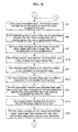
- FIGS. 3a and 3b are flowcharts illustrating a trip control process of the circuit breaker according to an embodiment of the present invention.
- a trip control apparatus and method for a circuit breaker according to the present invention will now be described in detail in connection with specific embodiments with reference to FIGS. 2 to 3b.
- FIG. 2 is a block diagram showing a trip control apparatus for a circuit breaker according to an embodiment of the present invention.
- a circuit breaker 100 includes a trip control apparatus comprising a break switch 110, a current sensor 130, a heat value management unit 150, a microprocessor 170, and a trip coil 190.
- the break switch 110 is disposed in a line along which an external power is supplied to a load, and is configured to shut off the power, supplied to the load, through a trip coil 190.
- the current sensor 130 is disposed on the line between the break switch 110 and the load, and is configured to sense the current supplied to the load.
- the current sensor 130 not also senses the current supplied to the load, but also acquires an operating power of the circuit breaker from the line and then supplies it to the load.
- the heat value management unit 150 is configured to store heat value data, received from the microprocessor 170, in matching with a time on which the heat value data is transmitted, but maintain the stored data using power supplied from the battery 160 at the time of powder-off.
- the heat value management unit 150 is also configured to transfer heat value-related data, including the stored heat value data at the request of the microprocessor 170, a time on which the heat value data was transferred and a current time, to the microprocessor 170.
- the heat value management unit 150 may be implemented using a common Real Time Counter (RTC) element.
- RTC Real Time Counter
- the heat value management unit 150 includes memory 155 and a time controller 151.
- the memory 155 is configured to store heat value data received from the microprocessor 170 and a time on which the heat value data is transferred.
- the time controller 151 is configured to check heat value data transferred from the microprocessor 170 and a time on which the heat value data is transferred, and store them in the memory 155.
- the time controller 151 is also configured to check the heat value data and the time on which the heat value data was transferred, which are stored in the memory 155, and a current time when the microprocessor 170 requests heat value-related data, and transfers them to the microprocessor 170.
- the time controller 151 calculates and acquires a time on the basis of a clock signal generated through a crystal oscillator.
- the microprocessor 170 When the current detected through the current sensor 130 is overcurrent, the microprocessor 170 accumulates and calculates the heat value of a load system due to the overcurrent during a predetermined trip delay time, and transfers a calculated heat value data to the heat value management unit 150. Further, when a calculated heat value data is higher than a predetermined value, the microprocessor 170 controls the trip coil 190 to shut off the power supplied to the load. If the break switch 110 is opened as the operating power is supplied through the current sensor 130 and the power is thus shut off, the microprocessor 170 cannot operate because it is not supplied with the operating power through the current sensor 130.
- the microprocessor 170 detects the current again through the current sensor 130. If overcurrent is detected again, the microprocessor 170 calculates the remaining heat value of the load system based on the heat value-related data stored in the heat value management unit 150, and variably decides a predetermined trip delay time based on the calculated remaining heat value.
- the microprocessor 170 calculates the remaining heat value by checking the elapsed time of the heat value data, and sets the trip delay time shorter when the remaining heat value is greater. What the remaining heat value is great is meant that the load system is in an overheating state due to previous overcurrent, etc. Therefore, in order to protect the load system, the microprocessor 170 controls the trip coil 190 more rapidly than a trip delay time where the remaining heat value is zero at normal times, and opens the break switch 110.
- the heat value management unit 150 transfers the heat value-related data at the request of the microprocessor 170.
- the heat value-related data includes heat value data, a time on which the heat value data is transferred, and a current time.
- the time on which the heat value data is transferred from the microprocessor 170 to the heat value management unit 150 is approximately identical to a time on which the operating power of the microprocessor 170 is removed.
- the current time transferred from the heat value management unit 150 to the microprocessor 170 is approximately identical to a time on which overcurrent is detected secondarily.
- the microprocessor 170 controls the trip coil 190 only when heat value data of the load system, which is calculated during a trip delay time, is higher than a predetermined value, so that the break switch 110 is opened.
- the microprocessor 170 does not open the break switch 110 when heat value data of the load system, which is calculated during a trip delay time, is lower than a predetermined value.
- the microprocessor 170 calculates heat value data when overcurrent is input and stores a calculated heat value data in the heat value management unit 150 for convenience of description. However, even when the current detected through the current sensor 130 does not exceed a predetermined overcurrent, the microprocessor 170 may calculate heat value data periodically and store a calculated heat value in the heat value management unit 150. Assuming that overcurrent is 110 % or more of a rating current, it is necessary to periodically store heat value data because 90% to 109% close to the rating current can also generate degradation of a load or line.
- the trip control apparatus 100 can be applied to a circuit breaker that is supplied with an operating power through the current sensor 130 or a current inductor embedded in a current sensor, and can be advantageously applied to an air circuit breaker.
- the circuit breaker 100 is first operated according to an operating power supplied from the current sensor 130.
- the current sensor 130 may include any kind of sensors, such as a current transformer, Rogowski or a shunt.
- the microprocessor 170 of the circuit breaker 100 detects a current, supplied to the load, through the current sensor 130, and determines whether a detected current is overcurrent (S1).
- the microprocessor 170 transfers the calculated heat value data to the heat value management unit 150 and also determines whether the calculated heat value data exceeds a predetermined reference value (S3).
- the microprocessor 170 controls the trip coil 190 to open the break switch 110, so that the power supplied to the load is shut off (S4). If the break switch 110 is opened, the microprocessor 170 is not supplied with the operating power through the current sensor 130 and therefore does not operate.
- the time controller 151 of the heat value management unit 150 is supplied with the heat value data from the microprocessor 170, checks a time on which the heat value data was transferred, and stores the beat value data and the time on which the heat value data was in the memory 155 (S5).
- the heat value management unit 150 is supplied with power from the battery 160 (that is, auxiliary power supply means) and maintains the information about the heat value data and the time on which the heat value data was transferred, which are stored in the memory 155 (S6).
- the heat value management unit 150 is configured to operate using the power supplied through the current sensor 130 at normal times, but to be supplied with the power of the battery 160 when the power is shut off.
- the microprocessor 170 of the circuit breaker is operated using the operating power supplied from the current sensor 130.
- the heat value management unit 150 is also automatically operated using the operating power supplied from the current sensor 130.
- the microprocessor 170 of the circuit breaker then controls the current sensor 130 to detect the current supplied to the load again, and determines whether a detected current is overcurrent (S7).
- the microprocessor 170 requests the heat value management unit 150 to transfer the stored heat value-related data thereto (S8).
- the time controller 151 of the heat value management unit 150 checks the heat value data and the time on which heat value was transferred, which are stored in the memory 155, and a current time, and transfers them to the microprocessor 170 (S9).
- the microprocessor 170 receives heat value-related data, including the heat value data, the time on which the heat value data was transferred, and the current time from the heat value management unit 150, and calculates the remaining heat value of the line and the load system (S10).
- the remaining heat value is acquired by calculating an elapsed time of the stored heat value data based on the time on which the heat value data was transferred and the current time.
- the microprocessor 170 can acquire the remaining heat value by calculating an elapsed time, which was taken to store the heat value data in the heat value management unit 150, and then searching for a value corresponding to the heat value data and the elapsed time through a previously stored reference table.
- the microprocessor 170 acquires the remaining heat value as described above, and sets the trip delay time short when the remaining heat value is great. This is for the purpose of protecting degradation or damage of the load system by setting the trip delay time shorter than that at normal times (when the remaining heat value is zero), that is, by rapidly opening the break switch 110 because the line and the load system is in an overheat state due to previous overcurrent.
- the microprocessor 170 variably decides a predetermined trip delay time based on the calculated remaining heat value (S 11)0
- the microprocessor 170 then calculates heat value according to overcurrent, which is generated from the line and the load system, for the decided trip delay time (S12).
- the microprocessor 170 transfers the calculated heat value data to the heat value management unit 150 and also determines whether the calculated heat value data exceeds a predetermined reference value (S13).
- the microprocessor 170 controls the trip coil 190 to open the break switch 110, so that the power supplied to the load is shut off (S14).
- the time controller 151 of the heat value management unit 150 is supplied with the heat value data from the microprocessor 170, checks a time on which the heat value data was transferred, and stores the heat value data and the time on which the heat value data was transferred in the memory 155.
- the heat value management unit 150 is supplied with the power from the battery 160 and maintains information about the heat value data and the time on which the heat value data was transferred, which are stored in the memory 155 (S15).
- the microprocessor 170 repeatedly performs the process of being supplied with heat value-related data from the heat value management unit 150, calculating the remaining heat value of the load system, and variably deciding a predetermined trip delay time based on the calculated remaining heat value (S7 to S15).
- the heat value management unit 150 such as a RTC element simulates data about the heat value of a line and a load and an elapsed time upon occurrence of overcurrent. Accordingly, the remaining heat value can be measured more accurately, error occurring when the device is implemented as an existing analog device can be minimized, a circuit can be simplified, and a more reliable and accurate operation can be accomplished under consecutive overcurrent fail conditions.
Landscapes
- Emergency Protection Circuit Devices (AREA)
Applications Claiming Priority (2)
| Application Number | Priority Date | Filing Date | Title |
|---|---|---|---|
| KR20060101066 | 2006-10-17 | ||
| KR1020070095914A KR100914830B1 (ko) | 2006-10-17 | 2007-09-20 | 차단기의 트립 제어장치 및 그 방법 |
Publications (2)
| Publication Number | Publication Date |
|---|---|
| EP1914778A2 true EP1914778A2 (de) | 2008-04-23 |
| EP1914778A3 EP1914778A3 (de) | 2009-11-11 |
Family
ID=38917632
Family Applications (1)
| Application Number | Title | Priority Date | Filing Date |
|---|---|---|---|
| EP07118627A Withdrawn EP1914778A3 (de) | 2006-10-17 | 2007-10-16 | Auslösesteuervorrichtung und -verfahren für einen Schutzschalter |
Country Status (1)
| Country | Link |
|---|---|
| EP (1) | EP1914778A3 (de) |
Cited By (2)
| Publication number | Priority date | Publication date | Assignee | Title |
|---|---|---|---|---|
| WO2017019301A1 (en) * | 2015-07-27 | 2017-02-02 | Sunpower Corporation | Thermal management of systems with electric components |
| WO2025152534A1 (zh) * | 2024-01-19 | 2025-07-24 | 广州汽车集团股份有限公司 | 过流保护方法、装置、车辆、电子设备及存储介质 |
Citations (1)
| Publication number | Priority date | Publication date | Assignee | Title |
|---|---|---|---|---|
| US4319298A (en) * | 1979-08-28 | 1982-03-09 | General Electric Company | Motor protection device |
Family Cites Families (7)
| Publication number | Priority date | Publication date | Assignee | Title |
|---|---|---|---|---|
| DE3137496C2 (de) * | 1981-09-21 | 1990-01-25 | Siemens AG, 1000 Berlin und 8000 München | Digitaler Überstromauslöser |
| FR2586489B1 (fr) * | 1985-08-23 | 1988-02-26 | Telemecanique Electrique | Dispositif de determination numerique et de sauvegarde d'une image thermique |
| US5136458A (en) * | 1989-08-31 | 1992-08-04 | Square D Company | Microcomputer based electronic trip system for circuit breakers |
| FR2651919B1 (fr) * | 1989-09-13 | 1995-12-15 | Merlin Gerin | Disjoncteur comportant un declencheur electronique. |
| US5303160A (en) * | 1992-01-13 | 1994-04-12 | Westinghouse Electric Corp. | Load controller with digitally modeled overload protection and analog tracking of heat state during power off |
| US5644510A (en) * | 1994-11-25 | 1997-07-01 | General Electric Company | Apparatus and method for motor overload protection using an elapsed-time signal for enabling computation of motor temperature data independently of temporary power interruption |
| US7369389B2 (en) * | 2005-12-08 | 2008-05-06 | General Electric Company | Electronic trip unit for circuit breakers |
-
2007
- 2007-10-16 EP EP07118627A patent/EP1914778A3/de not_active Withdrawn
Patent Citations (1)
| Publication number | Priority date | Publication date | Assignee | Title |
|---|---|---|---|---|
| US4319298A (en) * | 1979-08-28 | 1982-03-09 | General Electric Company | Motor protection device |
Cited By (3)
| Publication number | Priority date | Publication date | Assignee | Title |
|---|---|---|---|---|
| WO2017019301A1 (en) * | 2015-07-27 | 2017-02-02 | Sunpower Corporation | Thermal management of systems with electric components |
| US9985582B2 (en) | 2015-07-27 | 2018-05-29 | Sunpower Corporation | Thermal management of systems with electric components |
| WO2025152534A1 (zh) * | 2024-01-19 | 2025-07-24 | 广州汽车集团股份有限公司 | 过流保护方法、装置、车辆、电子设备及存储介质 |
Also Published As
| Publication number | Publication date |
|---|---|
| EP1914778A3 (de) | 2009-11-11 |
Similar Documents
| Publication | Publication Date | Title |
|---|---|---|
| CN101917035B (zh) | 电池组、电池保护处理装置及其启动控制方法 | |
| US7506183B2 (en) | Data authentication circuit, battery pack and portable electronic device | |
| US6437540B2 (en) | Battery pack | |
| US6501249B1 (en) | Battery management system | |
| KR101022630B1 (ko) | 배터리 팩, 배터리 보호 처리 장치, 및 배터리 보호 처리장치의 제어 방법 | |
| CN101083402B (zh) | 可充电电池的充电方法和用于可充电电池的保护电路 | |
| JPH05501992A (ja) | 少なくとも1つの再充電可能な電池から給電される記録装置の作動方法 | |
| US20090174410A1 (en) | Method and apparatus for controlling battery | |
| KR100914830B1 (ko) | 차단기의 트립 제어장치 및 그 방법 | |
| US8659277B2 (en) | Current providing method and current providing system | |
| US7039150B1 (en) | Serial interface for a battery management system | |
| US5551077A (en) | Portable telephone equipment with condition restoration | |
| EP1914778A2 (de) | Auslösesteuervorrichtung und -verfahren für einen Schutzschalter | |
| US5303160A (en) | Load controller with digitally modeled overload protection and analog tracking of heat state during power off | |
| US20040164714A1 (en) | AC adaptor | |
| US5973528A (en) | Control circuit and method for a temperature sensitive device | |
| JP2000050526A (ja) | 電源供給制御装置 | |
| US20180204699A1 (en) | Circuit interrupter including electronic trip unit and method of determining elapsed time of start-up process | |
| JP3208786B2 (ja) | 電池充電装置 | |
| EP0880086A1 (de) | Steuerschaltung und -verfahren für ein temperaturempfindliches Gerät | |
| JP3457681B2 (ja) | 充電装置 | |
| US11888310B1 (en) | Methods and apparatus for precharge monitoring of high voltage circuits | |
| JP2002270248A (ja) | 電池電圧検出装置及びその方法 | |
| JP2005185073A (ja) | 電源瞬断保護装置及び電子カメラ装置 | |
| JP7034387B2 (ja) | 緩放リレー回路および列車制御装置 |
Legal Events
| Date | Code | Title | Description |
|---|---|---|---|
| PUAI | Public reference made under article 153(3) epc to a published international application that has entered the european phase |
Free format text: ORIGINAL CODE: 0009012 |
|
| AK | Designated contracting states |
Kind code of ref document: A2 Designated state(s): AT BE BG CH CY CZ DE DK EE ES FI FR GB GR HU IE IS IT LI LT LU LV MC MT NL PL PT RO SE SI SK TR |
|
| AX | Request for extension of the european patent |
Extension state: AL BA HR MK RS |
|
| PUAL | Search report despatched |
Free format text: ORIGINAL CODE: 0009013 |
|
| AK | Designated contracting states |
Kind code of ref document: A3 Designated state(s): AT BE BG CH CY CZ DE DK EE ES FI FR GB GR HU IE IS IT LI LT LU LV MC MT NL PL PT RO SE SI SK TR |
|
| AX | Request for extension of the european patent |
Extension state: AL BA HR MK RS |
|
| 17P | Request for examination filed |
Effective date: 20100511 |
|
| 17Q | First examination report despatched |
Effective date: 20100609 |
|
| AKX | Designation fees paid |
Designated state(s): DE ES FR GB IT |
|
| STAA | Information on the status of an ep patent application or granted ep patent |
Free format text: STATUS: EXAMINATION IS IN PROGRESS |
|
| STAA | Information on the status of an ep patent application or granted ep patent |
Free format text: STATUS: THE APPLICATION IS DEEMED TO BE WITHDRAWN |
|
| 18D | Application deemed to be withdrawn |
Effective date: 20170413 |