EP1914785A2 - Aberrationskorrektor und Verfahren für Aberrationskorrektur - Google Patents
Aberrationskorrektor und Verfahren für Aberrationskorrektur Download PDFInfo
- Publication number
- EP1914785A2 EP1914785A2 EP07254102A EP07254102A EP1914785A2 EP 1914785 A2 EP1914785 A2 EP 1914785A2 EP 07254102 A EP07254102 A EP 07254102A EP 07254102 A EP07254102 A EP 07254102A EP 1914785 A2 EP1914785 A2 EP 1914785A2
- Authority
- EP
- European Patent Office
- Prior art keywords
- quadrupole
- field
- quadrupole field
- aberration
- electron beam
- Prior art date
- Legal status (The legal status is an assumption and is not a legal conclusion. Google has not performed a legal analysis and makes no representation as to the accuracy of the status listed.)
- Granted
Links
- 230000004075 alteration Effects 0.000 title claims abstract description 147
- 238000000034 method Methods 0.000 title claims description 16
- 230000005405 multipole Effects 0.000 claims abstract description 73
- 238000010894 electron beam technology Methods 0.000 claims abstract description 72
- 230000000694 effects Effects 0.000 claims abstract description 52
- 230000003287 optical effect Effects 0.000 claims abstract description 49
- 230000005686 electrostatic field Effects 0.000 claims description 7
- 201000009310 astigmatism Diseases 0.000 abstract description 15
- 230000005540 biological transmission Effects 0.000 abstract description 13
- 238000003384 imaging method Methods 0.000 abstract description 5
- 238000010586 diagram Methods 0.000 description 13
- 238000005286 illumination Methods 0.000 description 10
- 230000005684 electric field Effects 0.000 description 2
- 239000000523 sample Substances 0.000 description 2
- 238000004626 scanning electron microscopy Methods 0.000 description 2
- 206010010071 Coma Diseases 0.000 description 1
- 206010073261 Ovarian theca cell tumour Diseases 0.000 description 1
- 238000007796 conventional method Methods 0.000 description 1
- 230000006866 deterioration Effects 0.000 description 1
- 230000003071 parasitic effect Effects 0.000 description 1
- 208000001644 thecoma Diseases 0.000 description 1
Images



Classifications
-
- H—ELECTRICITY
- H01—ELECTRIC ELEMENTS
- H01J—ELECTRIC DISCHARGE TUBES OR DISCHARGE LAMPS
- H01J37/00—Discharge tubes with provision for introducing objects or material to be exposed to the discharge, e.g. for the purpose of examination or processing thereof
- H01J37/02—Details
- H01J37/04—Arrangements of electrodes and associated parts for generating or controlling the discharge, e.g. electron-optical arrangement or ion-optical arrangement
- H01J37/153—Electron-optical or ion-optical arrangements for the correction of image defects, e.g. stigmators
-
- H—ELECTRICITY
- H01—ELECTRIC ELEMENTS
- H01J—ELECTRIC DISCHARGE TUBES OR DISCHARGE LAMPS
- H01J2237/00—Discharge tubes exposing object to beam, e.g. for analysis treatment, etching, imaging
- H01J2237/153—Correcting image defects, e.g. stigmators
- H01J2237/1534—Aberrations
-
- H—ELECTRICITY
- H01—ELECTRIC ELEMENTS
- H01J—ELECTRIC DISCHARGE TUBES OR DISCHARGE LAMPS
- H01J2237/00—Discharge tubes exposing object to beam, e.g. for analysis treatment, etching, imaging
- H01J2237/26—Electron or ion microscopes
Definitions
- the present invention relates to an aberration corrector and a method of aberration correction and, more particularly, to aberration corrector and method of aberration correction for correcting chromatic aberration in the whole system created by an objective lens or a condenser lens.
- Spherical aberration is one factor causing a deterioration of the resolution in an electron beam system such as a transmission electron microscope (TEM) or scanning electron microscope (SEM). If it is possible to correct the chromatic aberration, the resolution will be improved. In a high-resolution electron microscope such as a transmission electron microscope, it is necessary to correct chromatic aberration in the whole system created by the objective lens or condenser lens.
- TEM transmission electron microscope
- SEM scanning electron microscope
- non-patent reference 1 a technique regarding correction of chromatic aberration utilizing a combination of magnetic and electric quadrupole elements is described.
- This is a method presently used in scanning electron microscopy (SEM).
- SEM scanning electron microscopy
- a deflecting force created by an electrostatic quadrupole element varies linearly in proportion to the angle (position within a multipole element).
- the deflecting force varies linearly in proportion to the angle and, therefore, the trajectory of the electron beam can be kept unchanged by causing one side of the quadrupole element to contribute in the direction of divergence from the optical axis and causing the other side to contribute in the converse direction.
- chromatic aberration correction can be made only in the x-direction or only in the y-direction.
- two correction systems are prepared to correct chromatic aberration in both directions.
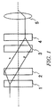
- Fig. 1 shows an example of an optical system for correction of chromatic aberration, the optical system utilizing a combination of magnetic and electrostatic quadrupole elements.
- This optical system corrects chromatic aberration produced in an objective lens (OL) 5.
- chromatic aberration correction can be made only in the x-direction. Therefore, a magnetic quadrupole element 1 for bringing the beam to a line focus is necessary.
- a combination of magnetic and electric quadrupole elements 2 superimposes magnetic and electric fields at the plane where the line focus has been achieved by the magnetic quadrupole element 1.
- chromatic aberration correction is made in the x-direction.
- chromatic aberration in the y-direction is corrected by a combination of magnetic and electric quadrupole elements 3.
- a quadrupole element 4 is placed between the combination of magnetic and electric quadrupole elements 3 and the objective lens 5 to return the beam to a round form from the state of the line focus.
- the optical system of Fig. 1 for aberration correction is intended to correct chromatic aberration in the objective lens 5 used in SEM. Therefore, the optical system assumes that the electron beam incident on the magnetic quadrupole element 1 has been sharply focused.
- STEM mode scanning mode
- the method used in SEM can be employed in principle.
- TEM mode transmission mode
- SEM or STEM mode a sharply focused electron beam is made to hit a specimen and so it suffices to make chromatic aberration correction only regarding the electron beam close to the focal point.
- an aberration corrector which is capable of correcting chromatic aberration in a lens disposed in the direction of motion of an electron beam using a relatively simple correction system and which achieves high-resolution imaging in a high-resolution electron microscope such as a transmission electron microscope. It would be further desirable to provide a method of aberration correction implemented by this aberration corrector. It would be still further desirable to provide chromatic aberration corrector and method of chromatic aberration correction.
- the first and second quadrupole field-producing multipole elements produce first and second quadrupole fields, respectively.
- the first and second quadrupole fields create optical systems each having a two-fold astigmatic effect of a primary term and a focusing effect in the direction of divergence of a cylindrically symmetrical type.
- the focusing effect in the direction of divergence of the cylindrically symmetrical type is caused by higher-order terms of the quadrupole field having magnitudes increasing at higher rates than the primary term when the length is increased.
- An aberration corrector causes the aforementioned quadrupole field-producing multipole elements to produce the quadrupole fields having higher-order terms, previously finds the relationship between the magnitude of the focusing effect in the direction of divergence of the cylindrically symmetrical type caused by the higher-order terms of each quadrupole field and the length of the quadrupole field in the direction of motion of the electron beam, and determines the length of the quadrupole field in the direction of motion of the electron beam necessary to correct the aberration in the lens using the relationship and based on the magnitude of the effect necessary to correct the aberration.
- a pair of transfer lenses is disposed between the first and second quadrupole field-producing multipole elements.
- the quadrupole fields produced respectively by the first and second quadrupole field-producing multipole elements are different from each other in length taken in the direction of motion of the electron beam.
- each of the quadrupole field-producing multipole elements acts to produce an electrostatic or electric two-fold field by superimposing a quadrupole field onto a dodecapole (12-pole) element using an electrostatic or a magnetic field or both.
- each of the quadrupole field-producing multipole elements acts to produce an electrostatic or electric two-fold field by superimposing a quadrupole field onto an octopole element using an electrostatic or a magnetic field or both.
- a lens disposed in the direction of motion of an electron beam can be corrected for chromatic aberration with a relatively simple correction system even where the beam is of the cylindrically symmetrical type and has spread. Therefore, high-resolution imaging can be accomplished in a high-resolution electron microscope such as a transmission electron microscope.
- An embodiment of the present invention which is described below is an aberration corrector incorporated in the illumination system of a transmission electron microscope.
- This aberration corrector in the illumination system corrects chromatic aberration in an objective lens or in a condenser lens by the use of two-fold fields (quadrupole field) produced by electrostatic multipole elements, magnetic multipole elements, or a combination of both electrostatic and magnetic multipole elements (i.e., using a superimposition of electrostatic and magnetic fields).
- an optical system having a focusing effect in the direction of divergence of a cylindrically symmetrical type is created by a quadrupole field having a thickness to correct chromatic aberration.
- This optical system may be hereinafter abbreviated as the "optical system having a concave lens effect” or simply “concave lens".
- the concave lens effect created by the quadrupole field having a thickness (length in the direction of motion of the electron beam) is employed for correction of chromatic aberration. This is different from the method which is used in scanning electron microscopy (SEM) and which utilizes superimposition of electric and magnetic fields (see, for example, the description of the prior art in patent reference 1 ( Japanese Patent Laid-Open No. 2003-203593 )).
- the multipole element has thickness (length in the direction of motion in the electron beam) is described.
- a quadrupole element has an essential function of producing a two-fold field.
- a hexapole element has an essential function of producing a three-fold field.
- Each of these fields is referred to as the primary term in the multipole field.
- An actual multipole element produces fields by higher-order terms other than the primary term though the produced fields are quite weak.
- higher-order terms other than the primary term are neglected in applications of the multipole element or simply act as parasitic factors.
- the thickness of the multipole element is increased, the effects of the higher-order terms other than the primary term manifest themselves.
- a multipole element having a length in the direction of motion of the electron beam which permits the effects of the higher-order terms to be used is necessary to correct chromatic aberration in a multipole element producing a quadrupole field and having thickness (length in the direction of motion of the electron beam).
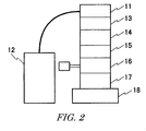
- Fig. 2 is a diagram showing the structure of a transmission electron microscope having an aberration corrector in the illumination system.
- the microscope has an electron gun 11 using a high-voltage power supply that is controlled by a high-voltage controller 12. Under this condition, the gun 11 produces an electron beam that is converged by a condenser lens 13 including stigmatic correcting elements. The converged beam reaches the aberration corrector 14 in the illumination system.
- the corrector 14 has various correcting elements including electron beam-deflecting elements and multipole elements. Especially, in the present embodiment, a multipole element having thickness (length in the direction of motion of the electron beam) is used to produce a quadrupole field. Chromatic aberration is corrected by the concave lens effect produced by the quadrupole field.
- the electron beam having aberrations which have been corrected by the aberration corrector 14 in the illumination system is passed through another condenser lens 15 including electron beam-deflecting elements.
- the beam reaches an objective lens and specimen stage 16.
- the objective lens causes the beam to hit a specimen placed on the specimen stage.
- the beam transmitted through the specimen lying on the specimen stage is projected by intermediate and projector lenses 17 and reaches an observation chamber 18, where an image of the specimen is observed. For example, the image is photographed by a camera.
- the aberration corrector 14 in the illumination system uses a quadrupole field having a length in the direction of motion in the electron beam (i.e., having so-called thickness) as mentioned previously.
- the quadrupole field having thickness shows a concave lens action having two-fold astigmatism and cylindrical symmetry.
- the optical system producing the concave lens action (quadrupole field having thickness) is used for correction of chromatic aberration in the whole system produced by the objective lens or condenser lens.
- a position is given by r in terms of complex notation.
- r' be a gradient.
- ⁇ be a complex angle.
- a derivative of the complex angle is given by ⁇ '.
- a 2 be a coefficient of the two-fold astigmatism per unit length.
- a two-fold astigmatism (geometric aberration) is given by Eq. (1) using A 2 and the complex conjugate of ⁇ .
- f 0 be the focal length of an axially symmetrical magnetic objective lens that is generally used in a transmission electron microscope.
- An optical system producing a concave lens effect is created from an electrostatic quadrupole field, a magnetic quadrupole field,or a superimposition of electrostatic and magnetic quadrupole fields.
- the electrostatic quadrupole field or magnetic quadruple field is created using a quadrupole field-producing multipole element and has thickness (length in the direction of motion of the electron beam).
- a lens can be corrected for chromatic aberration by creating an optical system acting as a concave lens that is different in refractive index (the dependence of the deflecting force on accelerating voltage or wavelength) from the lens.
- the optical system is created from an electrostatic quadrupole field, a magnetic quadrupole field, or a superimposition of electrostatic and magnetic quadrupole fields.
- the electrostatic quadrupole field or magnetic quadrupole field has thickness.
- n and m are integers (n, m > 0).
- Eq. (8) represents a lens effect.
- the terms have different orders for the thickness t.
- 2(n-1) indicating two-fold astigmatism within Eq. (4) has been canceled out in Eq. (8).
- Fig. 3 The configuration of Fig. 3 is an example in which chromatic aberration produced in an objective lens 25 is corrected by using two quadrupole field-producing multipole elements having thickness.
- a coma-free surface 25a and a specimen surface 25b are formed on the obj ective lens 25.
- the coma-free surface 25a is substantially coincident with the front focal plane.
- Each of a first quadrupole field-producing multipole element 21 and a second quadrupole field-producing multipole element 23 has thickness (length in the direction of motion of the electron beam).
- chromatic aberration is produced in the first quadrupole field-producing multipole element 21, surplus two-fold astigmatism may remain.
- the two-fold astigmatism is removed by inserting the second quadrupole field-producing multipole element 23 such as a second quadrupole field.
- the second quadrupole field-producing multipole element 23 is reversed in polarity from the first multipole element 21.
- a transfer lens pair consisting of lenses 22a and 22b is inserted between the first quadrupole field-producing multipole element 21 and the second quadrupole field-producing element 23.
- a transfer lens pair consisting of lenses 24a and 24b is inserted between the second quadrupole field-producing multipole element 23 and the objective lens 25.
- the transfer lenses which are unnecessary in the aberration-correcting optical systemof SEM are used in the chromatic aberration-correcting optical system of the present embodiment for the following reason.
- the electron beam spreading over the whole field of view i.e., cylindrically symmetrical electron beam having spread
- the electron beam should be deflected only in a space that does not depend on the position of the beam. Consequently, the multipole elements need to act totally in a reverse space.
- electrons need to be transferred between the multipole elements through the reverse space using the transfer lenses.
- the aberration corrector having the optical system shown in Fig. 3 can correct the cylindrically symmetrical electron beam having spread for chromatic aberration with a relatively simple correction system.
- transfer lenses are not always necessary.
- a pair of transfer lenses may be placed between two electrostatic quadrupole fields having thickness. Further, a pair of transfer lenses may be placed between two magnetic quadrupole fields having thickness. Yet further, a pair of transfer lenses may be placed between two quadrupole fields in each of which an electrostatic quadrupole field and a magnetic quadrupole field, both having thickness, are superimposed. Still further, a pair of transfer lenses may be placed between the aforementioned second quadrupolefield-producing multipole elements and the objective lens.
- optical system producing a concave lens effect by means of quadrupole fields which are identical in refractive index with the objective lens.
- chromatic aberration coefficient C c U d f d U
- the chromatic aberration can be finally reduced down to f 0 - f by correcting the chromatic aberration produced in the whole objective lens by the chromatic aberration produced by the concave lens.
- a concave lens by superimposing an electrostatic quadrupole field and a magnetic quadrupole field having thickness, even if the concave lens is identical in refractive index with the objective lens, and by making use of the fact that the absolute value of a negative amount of chromatic aberration of the concave lens is greater than the amount of chromatic aberration of the objective lens.
- the electron optical system of a transmission electron microscope can be corrected for chromatic aberration, using an optical system acting as a concave lens which is produced by quadrupole fields and which is identical in refractive index with the objective lens.
- optical system of embodiments of the present invention capable of correcting chromatic aberration canbe modified as follows.
- Two electrostatic quadrupole field-producing multipole elements having different thicknesses (lengths in the direction of motion of the electron beam) may be used.
- two magnetic quadrupole field-producing multipole elements having different thicknesses (lengths in the direction of motion of the electron beam) may be used.
- two multipole elements which are different in thickness and in each of which an electrostatic quadrupole field and a magnetic quadrupole field are superimposed may be used.
- a quadrupole element produces a two-fold field.
- quadrupole field-producing multipole element for producing a two-fold field for implementing embodiments of the present invention are as follows: a hexapole element on which a quadrupole field is superimposed to produce an electrostatic or electric two-fold field; a dodecapole (12-pole) element on which a quadrupole field is superimposed to produce an electrostatic or electric two-fold field; and an octopole element on which a quadrupole field is superimposed to produce an electrostatic or electric two-fold field.
- Figs. 4-7 show the configurations of the aforementioned electrostatic quadrupole element, magnetic quadrupole element, electrostatic field-magnetic field superimposed quadrupole element, and electrostatic field-magnetic field superimposed hexapole element, respectively.
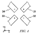
- Fig. 4 is a schematic diagram of the electrostatic quadrupole element.
- a positive pole 31, a negative pole 32, a positive pole 33, and a negative pole 34 forming an electrostatic quadrupole element are arranged on the xy-plane perpendicular to the direction of motion z of the electron beam.
- Each pole has thickness in the direction of motion z of the electron beam.
- Fig. 5 is a schematic diagram of the magnetic quadrupole element.
- An S-pole 41, an N-pole 42, an S-pole 43, and an N-pole 44 forming the magnetic quadrupole element are arranged on the xy-plane perpendicular to the direction of motion z of the electron beam.
- Each pole has thickness in the direction of motion z of the electron beam.
- Fig. 6 is a schematic diagram of the electrostatic field-magnetic field superimposed quadrupole element.
- An S-pole 41, a positive pole 31, an N-pole 42, a negative pole 32, an S-pole 43, a positive pole 33, an N-pole 44, and a negative pole 34 are arranged on the xy-plane perpendicular to the direction of motion z of the electron beam.
- Each pole has thickness in the direction of motion z of the electron beam.
- Fig. 7 is a schematic diagram of the electrostatic field-magnetic field superimposed hexapole element.
- a negative pole 51, an S-pole 52, a positive pole 53, an N-pole 54, a negative pole 55, an S-pole 56, a positive pole 57, an N-pole 58, a negative pole 59, an S-pole 60, a positive pole 61, and an N-pole 62 are arranged on the xy-plane perpendicular to the direction of motion z of the electron beam.
- Each pole has thickness in the direction of motion z of the electron beam.
- Fig. 3 shows a specific example of the configuration of an aberration corrector.
- two quadrupole field-producing multipole elements 21 and 23 are used.
- the quadrupole field-producing multipole element 21 and transfer lens 22 of Fig. 3 are omitted.
- quadrupole field-producing multipole element 23 may be used without using the transfer lens 24.
- correction of chromatic aberration in an illumination system for forming a probe to be directed to a specimen is taken as an example.
- the invention can also be applied to correction of chromatic aberration in an imaging system.
- Embodiments of the present invention are intended to correct a lens for an aberration for a cylindrically symmetrical electron beam having spread.
- the cylindrically symmetrical electron beam is not always required to have a cross section that is circular when hitting the specimen.
- embodiments of the present invention can also be applied to the case where the cross section of an electron beam is shaped into a noncircular form using a rectangular slit or the like.
Landscapes
- Chemical & Material Sciences (AREA)
- Analytical Chemistry (AREA)
- Particle Accelerators (AREA)
- Electron Sources, Ion Sources (AREA)
- Electron Beam Exposure (AREA)
Applications Claiming Priority (1)
| Application Number | Priority Date | Filing Date | Title |
|---|---|---|---|
| JP2006287009 | 2006-10-20 |
Publications (3)
| Publication Number | Publication Date |
|---|---|
| EP1914785A2 true EP1914785A2 (de) | 2008-04-23 |
| EP1914785A3 EP1914785A3 (de) | 2014-03-19 |
| EP1914785B1 EP1914785B1 (de) | 2016-09-14 |
Family
ID=38968172
Family Applications (1)
| Application Number | Title | Priority Date | Filing Date |
|---|---|---|---|
| EP07254102.2A Ceased EP1914785B1 (de) | 2006-10-20 | 2007-10-17 | Aberrationskorrektor und Verfahren für Aberrationskorrektur |
Country Status (2)
| Country | Link |
|---|---|
| US (1) | US20080093563A1 (de) |
| EP (1) | EP1914785B1 (de) |
Families Citing this family (7)
| Publication number | Priority date | Publication date | Assignee | Title |
|---|---|---|---|---|
| JP5226367B2 (ja) * | 2007-08-02 | 2013-07-03 | 日本電子株式会社 | 収差補正装置 |
| JP5545869B2 (ja) * | 2010-11-16 | 2014-07-09 | 日本電子株式会社 | 荷電粒子線の軸合わせ方法及び荷電粒子線装置 |
| JP5934517B2 (ja) * | 2012-02-24 | 2016-06-15 | 日本電子株式会社 | 色収差補正装置及び色収差補正装置の制御方法 |
| US8541755B1 (en) * | 2012-05-09 | 2013-09-24 | Jeol Ltd. | Electron microscope |
| WO2017193061A1 (en) * | 2016-05-06 | 2017-11-09 | Weiwei Xu | Miniature electron beam lens array use as common platform ebeam wafer metrology, imaging and material analysis system |
| KR20240097977A (ko) | 2017-09-29 | 2024-06-27 | 에이에스엠엘 네델란즈 비.브이. | 하전 입자 빔 검사를 위한 샘플 사전-충전 방법들 및 장치들 |
| JP7465295B2 (ja) * | 2022-02-22 | 2024-04-10 | 日本電子株式会社 | 収差補正装置および電子顕微鏡 |
Family Cites Families (6)
| Publication number | Priority date | Publication date | Assignee | Title |
|---|---|---|---|---|
| DE3841715A1 (de) * | 1988-12-10 | 1990-06-13 | Zeiss Carl Fa | Abbildender korrektor vom wien-typ fuer elektronenmikroskope |
| NL9100294A (nl) * | 1991-02-20 | 1992-09-16 | Philips Nv | Geladen deeltjesbundelinrichting. |
| DE10044199B9 (de) * | 2000-09-07 | 2005-07-28 | Carl Zeiss Smt Ag | Ablenkanordnung und Projektionssystem für geladene Teilchen |
| US6723997B2 (en) * | 2001-10-26 | 2004-04-20 | Jeol Ltd. | Aberration corrector for instrument utilizing charged-particle beam |
| US6924488B2 (en) * | 2002-06-28 | 2005-08-02 | Jeol Ltd. | Charged-particle beam apparatus equipped with aberration corrector |
| JP2005353429A (ja) * | 2004-06-11 | 2005-12-22 | Hitachi Ltd | 荷電粒子線色収差補正装置 |
-
2007
- 2007-10-17 EP EP07254102.2A patent/EP1914785B1/de not_active Ceased
- 2007-10-18 US US11/874,646 patent/US20080093563A1/en not_active Abandoned
Also Published As
| Publication number | Publication date |
|---|---|
| EP1914785B1 (de) | 2016-09-14 |
| US20080093563A1 (en) | 2008-04-24 |
| EP1914785A3 (de) | 2014-03-19 |
Similar Documents
| Publication | Publication Date | Title |
|---|---|---|
| US8178850B2 (en) | Chromatic aberration corrector for charged-particle beam system and correction method therefor | |
| US9793088B2 (en) | Two-stage dodecapole aberration corrector for charged-particle beam | |
| EP2020673B1 (de) | Aberrationskorrektursystem | |
| JP3207196B2 (ja) | 高解像度荷電粒子線装置用の補正装置 | |
| EP1914785B1 (de) | Aberrationskorrektor und Verfahren für Aberrationskorrektur | |
| EP2325863B1 (de) | Korrektor für axiale Aberrationen einer teilchenoptischen Linse | |
| US9349565B2 (en) | Multipole lens, aberration corrector, and electron microscope | |
| US20030122076A1 (en) | Charged-particle beam apparatus equipped with aberration corrector | |
| US8785880B2 (en) | Chromatic aberration corrector and electron microscope | |
| EP2453463B1 (de) | Verfahren zur Herstellung einer axialen Ausrichtung eines geladenen Teilchenstrahls und geladenes Teilchenstrahlsystem | |
| JP6647854B2 (ja) | 収差補正方法および荷電粒子線装置 | |
| EP2388795A2 (de) | Korrektor der sphärische Abberation und Verfahren zur Korrektur der sphärischen Abberation | |
| US20080054186A1 (en) | Method of Aberration Correction and Electron Beam System | |
| JP6843794B2 (ja) | 収差補正装置および荷電粒子線装置 | |
| JP5069066B2 (ja) | 収差補正装置及び収差補正方法 | |
| US8791423B2 (en) | Aberration correction device and charged particle beam device employing same | |
| Rose et al. | Magnetic Cc/Cs-corrector compensating for the chromatic aberration and the spherical aberration of electron lenses | |
| JP2003502802A (ja) | 粒子レンズの色収差を除去する静電修正器 | |
| JP4135221B2 (ja) | 写像型電子顕微鏡 | |
| US7973289B2 (en) | Method for producing image contrast by phase shifting in electron optics | |
| JP3692011B2 (ja) | 磁界型エネルギーフィルタ | |
| JP2007242490A (ja) | 荷電粒子線光学系用の収差補正光学装置及び光学系 |
Legal Events
| Date | Code | Title | Description |
|---|---|---|---|
| PUAI | Public reference made under article 153(3) epc to a published international application that has entered the european phase |
Free format text: ORIGINAL CODE: 0009012 |
|
| AK | Designated contracting states |
Kind code of ref document: A2 Designated state(s): AT BE BG CH CY CZ DE DK EE ES FI FR GB GR HU IE IS IT LI LT LU LV MC MT NL PL PT RO SE SI SK TR |
|
| AX | Request for extension of the european patent |
Extension state: AL BA HR MK RS |
|
| PUAL | Search report despatched |
Free format text: ORIGINAL CODE: 0009013 |
|
| AK | Designated contracting states |
Kind code of ref document: A3 Designated state(s): AT BE BG CH CY CZ DE DK EE ES FI FR GB GR HU IE IS IT LI LT LU LV MC MT NL PL PT RO SE SI SK TR |
|
| AX | Request for extension of the european patent |
Extension state: AL BA HR MK RS |
|
| RIC1 | Information provided on ipc code assigned before grant |
Ipc: H01J 37/153 20060101AFI20140207BHEP |
|
| 17P | Request for examination filed |
Effective date: 20140919 |
|
| RBV | Designated contracting states (corrected) |
Designated state(s): AT BE BG CH CY CZ DE DK EE ES FI FR GB GR HU IE IS IT LI LT LU LV MC MT NL PL PT RO SE SI SK TR |
|
| AKX | Designation fees paid |
Designated state(s): DE NL |
|
| GRAP | Despatch of communication of intention to grant a patent |
Free format text: ORIGINAL CODE: EPIDOSNIGR1 |
|
| INTG | Intention to grant announced |
Effective date: 20160411 |
|
| GRAS | Grant fee paid |
Free format text: ORIGINAL CODE: EPIDOSNIGR3 |
|
| GRAA | (expected) grant |
Free format text: ORIGINAL CODE: 0009210 |
|
| AK | Designated contracting states |
Kind code of ref document: B1 Designated state(s): DE NL |
|
| REG | Reference to a national code |
Ref country code: NL Ref legal event code: FP |
|
| REG | Reference to a national code |
Ref country code: DE Ref legal event code: R096 Ref document number: 602007047903 Country of ref document: DE |
|
| REG | Reference to a national code |
Ref country code: DE Ref legal event code: R097 Ref document number: 602007047903 Country of ref document: DE |
|
| PLBE | No opposition filed within time limit |
Free format text: ORIGINAL CODE: 0009261 |
|
| STAA | Information on the status of an ep patent application or granted ep patent |
Free format text: STATUS: NO OPPOSITION FILED WITHIN TIME LIMIT |
|
| 26N | No opposition filed |
Effective date: 20170615 |
|
| PGFP | Annual fee paid to national office [announced via postgrant information from national office to epo] |
Ref country code: NL Payment date: 20201028 Year of fee payment: 14 |
|
| PGFP | Annual fee paid to national office [announced via postgrant information from national office to epo] |
Ref country code: DE Payment date: 20201022 Year of fee payment: 14 |
|
| REG | Reference to a national code |
Ref country code: DE Ref legal event code: R119 Ref document number: 602007047903 Country of ref document: DE |
|
| REG | Reference to a national code |
Ref country code: NL Ref legal event code: MM Effective date: 20211101 |
|
| PG25 | Lapsed in a contracting state [announced via postgrant information from national office to epo] |
Ref country code: NL Free format text: LAPSE BECAUSE OF NON-PAYMENT OF DUE FEES Effective date: 20211101 Ref country code: DE Free format text: LAPSE BECAUSE OF NON-PAYMENT OF DUE FEES Effective date: 20220503 |